
6 TENSILE INTEGRITY BY ELECTRONIC COMPUTER
6.1 I
2FULLER’S imagination, having spun a tensile web of architecture from the octahedron, turned next to the practical problem of how to manufacture the octahedron itself. This peculiar figure, with its maze of slim wires strung around three axial struts, posed a challenge in production technique. The struts had to be floated in their sea of twelve tension members, and, until the tension net was complete and stressed, there was really nothing to hold the complex in any shape at all. Besides, the three struts had to be held in a criss-crossed arrangement, each at just the right angle to the others and with their vertexial ends correctly disposed to put each of the six vertexes of the octahedron exactly where they should be.
3 The geometry of the octahedron established the starting point for Fuller’s invention of a method and apparatus for spinning octahedral building ‘‘blocks’’ of forms which can be varied at will to meet a wide range of construction needs. The three struts, held in predetermined angular relation, form a preliminary assembly which is rotated while a wire is fed through a guide in such a way as to attach itself to the ends of the struts. Meanwhile, the wire guide is moved to and fro in timed relation to rotation of the strut assembly, bringing the wire sequentially over the several ends of the three struts. By choosing just the right sequence, the wires can be set up to make the twelve edges of a complete octahedron without the need to reverse rotation of the strut assembly. An intriguing aspect of this procedure is that simple two-dimensional movements of the wire guide to and fro in a single plane will result in the production of the three- dimensional octahedron.
4 Describing his invention, Fuller speaks of the ‘‘seemingly complex but truly simple form of the octahedral unit.’’ As man’s works conform imperfectly to nature, they possess unnatural complexity, though perhaps seeming to be simple. So deceptive is the semblance of simplicity that often it can be dissembled only upon long studied analysis. To opposite effect, nature shows us much that has an appearance of complexity but which can prove to be basically simple. Take the case of the rectilinear building that ‘‘wants to fall down,’’ as Fuller taught us, but which is gusseted against doing so. Such a building is deceptively simple in its rectangular prismatic form—you don’t see the gussets, or, if you do, you pay them little heed as you are so well accustomed to them. Then consider the building of geodesic form which instantly suggests a complexity of spherical geometry, but does so only when approached from the rectilinear foundation of Euclidean geometry. This same geodesic form, when observed against She background of Fuller’s energetic/synergetic geometry, is easily comprehended as the entrancingly simple fact of nature that it is.
5 A partner in true simplicity is the octahedron. Even when spun in the form which outlines not only the octahedron but also its three axes, we see more, not less, of octahedral structuring, for the three axes of the octa at once define its unique geometry. What at first may seem only to be a strange array of struts floating in a web of tension wires becomes, upon informed analysis, a simple octahedron, for the web is observed to define the eight triangular faces, twelve edges and six vertexes, while during the spinning of the octahedral building unit, data of the correlated movements of the spinner and wire feed guide are stored for ‘‘play-back’’ in the forming of duplicate units. Thus a particular design of unit becomes the progenitor of others of the same species. But more, the play-back programs can be created with the use of electronic computers in which data are stored for a myriad of octahedral variants.
6 The octahedral building unit is a true member of Fuller s tensegrity family. And here we witness the phenomenon of creation of a tensegrity complex by computer. By this ingenious extrapolation on nature’s own tension plan of the universe, Fuller has taken one more step in turning its energies to greater human advantage.
6.2 II
8IN March of 1965, Fuller filed application in Washington to patent his octa spinning invention. Action on the application was taken by the Patent Office two years later. In a letter dated March 15,1967, the examiner reported that he had examined the application and had determined that Fuller's claims could not be allowed. His rejection was based, not on anticipation by others, but on his feeling that the invention was obvious from what was shown in a number of previous patents, for these could be so altered and combined one with another as to re-create Fuller’s concept. In finding that the method was obvious, the examiner suggested how a 1956 patent for a yam winding reel might be modified by using it in combination with an indexing operation shown by a patent issued in 1893. Fuller’s invention was resubmitted with supporting argument. When, in December of 1967, the claims were rejected for a second time, the inventor’s counsel advised him that, ‘‘The examiner does not have any reference which anticipates the real concept of the invention,’’ and that it remained to seek a favorable ruling by arranging an oral interview at the Patent Office. If the examiner could not then be persuaded to allow the claims, an appeal would be necessary.
9 Always Fuller had been successful in obtaining patents for his inventions, although often the difficulties usual to any patent prosecution were the greater because the inventions were of such fundamental nature. It is harder to get a broad patent than a narrow one, and octa spinning was a highly imaginative invention which imposed a breadth of claiming that augured a long, hard battle in Washington. This time, Fuller decided not to accept the burden of prolonging the patent prosecution. So the application was dropped without presentation of oral argument, and there is no way of knowing whether a patent might ultimately have been granted.
10 Strong motivation for Fuller’s patenting program round the world was born of his natural drive to teach, not alone from thoughts of pecuniary advantage to be derived from licensing royalties. He never entered actively into licensing proposals or negotiations, preferring to leave that to his business and legal aides. These he encouraged not to solicit licensees, but only to handle requests for licenses when received, or, when occasion demanded as where there seemed likelihood that someone was preparing to infringe one of his patents, then to call the prospective infringer’s attention to the patent, and to the availability of a license. While Fuller did not wish to seek patent profits by ‘‘selling’’ efforts, he was adamant in seeking to forestall efforts of others to profit by making unauthorized use of his inventions. As he made those inventions available to all at reasonable cost, the patents became widely licensed and no need arose to bring action in the courts to enforce them.
11 The royalties received were plowed back into the businesses of geodesic enthusiasts in Geometries, Inc., Synergetics, Inc., and Geodesics, Inc., at Cambridge and Raleigh, themselves ‘‘teachers’’ of the geodesic art. Hence in the strictest sense, Fuller’s ultimate preoccupation was with education, not profits. The patents, when royalties came, were being used to spread knowledge of the inventions and the gain to others in using them. Besides, the printing of the patents round the world and their distribution to libraries made the inventions better known so that one day when the patents expired all might benefit from their teachings. That this aim in itself formed a significant part of Fuller’s philosophy of patenting (as it does in the rationale of government awards of patent monopolies for limited periods of time) may be deduced from the fact that Fuller derived little in the way of royalty return on his foreign patent investment. Yet during three decades he continued to patent his inventions throughout the world. And the true answer is not that his motivation was only the distant prospect of foreign royalties. On one occasion when faced with mounting bills for foreign patent taxes and pressed by counsel’s questions about his commercial prospects in some faraway land, Fuller replied, ‘‘I believe it is good to have patents in existence everywhere for people to read in the libraries of their own countries and in their own languages.’’ To him there was intrinsic worth in having patents issued and printed, profits or no.
12 Fuller’s decision to forego patenting his octa spinning invention was disappointing to him if only because it meant that no patent would be published. At great personal sacrifice, he had fulfilled a demanding round the world schedule of lecturing and of teaching in the universities. It was his wish that his inventions be described in the libraries of patents. This was another chapter in his one-man teaching saga. And there would be no printed teaching of this invention by any United States patent. Fuller has requested the author to remedy this by publishing his full patent disclosure as a part of the story of his inventions, a story which otherwise would not be as complete as he would like it to be. The full patent specification is given in the succeeding chapter.
6.3 III
14THE invention relates to the fabrication of building trusses and components.
15 My United States patent, No. 3,354,591, granted December 7, 1964, describes a truss construction which is capable of utilizing more efficiently the tensile strengths of the materials from which the truss is constructed. In such construction, it has been found possible to use many elements loaded purely in tension, indeed, one in which such purely tensioned elements predominate so that relatively few compression members are needed. The construction is one in which a number of units, conveniently made of criss-crossed struts bound together by a network of tension elements, form the basic components, or ‘‘building blocks'’’ used in putting together the truss. While such truss components, once assembled, are self-contained units that are easy to handle, their fabrication can become rather complex due to the fact that they are made up of compression struts which are virtually suspended in a network of wire. During fabrication, it is essential to maintain the proper angular relationship between the criss-crossed struts and the relative dispositions of the ends of the struts for a given predetermined angular relation.
16 My present invention is concerned with the solution of the particular problems involved in the fabrication of these peculiar strut-and-wire components such as those exemplified in my prior patent aforesaid, and to the means by which such components can be interconnected to form a building truss.
17 According to one form of my invention, the truss structure produced comprises a number of interconnected three- dimensional components each of which has several struts, and flexible edge portions extending between the ends of the struts to form an initially self-supporting unit. These components are joined together by connecting the ends of the struts of one component to the ends of the struts of adjacent components through partly spherical fastening elements perforated to provide selective adjustment of the angular relationship between the struts of the interconnected components.
18 Fabrication of the truss components comprises the steps of arranging the struts in predetermined angular relation to one another to form a preliminary strut assembly, rotating the strut assembly, feeding a wire for attachment to the ends of the struts, and producing relative movements between the rotating strut assembly and the wire feed to bring the wire into engagement with first one strut and then another, thus to form flexible edge portions of the truss component. My apparatus includes means for performing these several steps in the desired sequence, and for programming the wire feeding device according to predetermined design patterns for components of varying form.
19 The invention has particular application to the fabrication of components of octahedral form comprising eight triangular faces. These faces are defined by the wire network, and there are three compression struts which are arranged along the three axes of the octahedron.
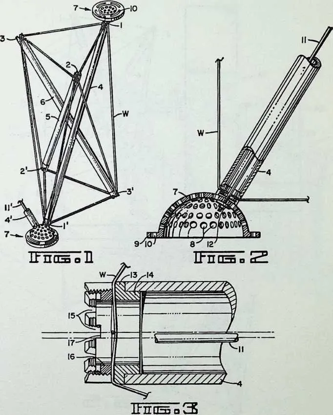
20 Figure 1 depicts a single octahedral component in perspective. Figure 2 is a view of one of the partly spherical fastenings of the same component. Figure 3 is an enlarged detail of an end of one of the struts, with associated wire-fastening means.
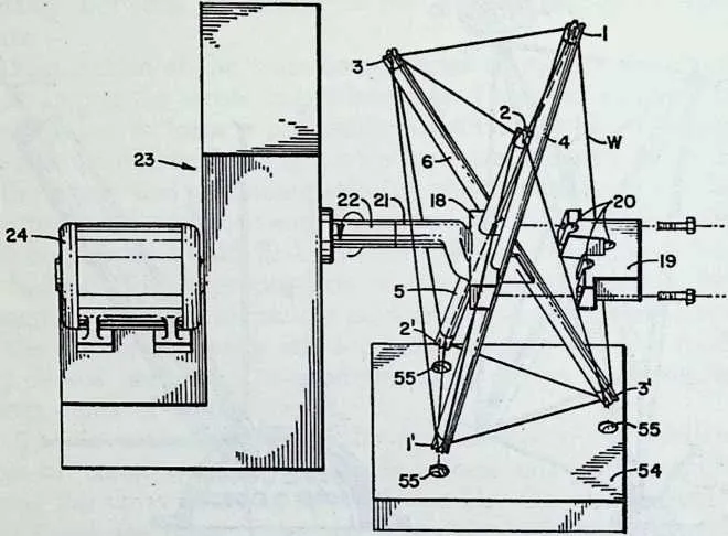
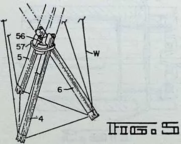
22 In Figure 4, we see in isometric perspective the apparatus which ‘‘spins’’ the wire onto the struts; in Figure 5 an optional form of means for binding the struts together after the completed octahedral component has been removed from the spinner.
24 IbnnSQ
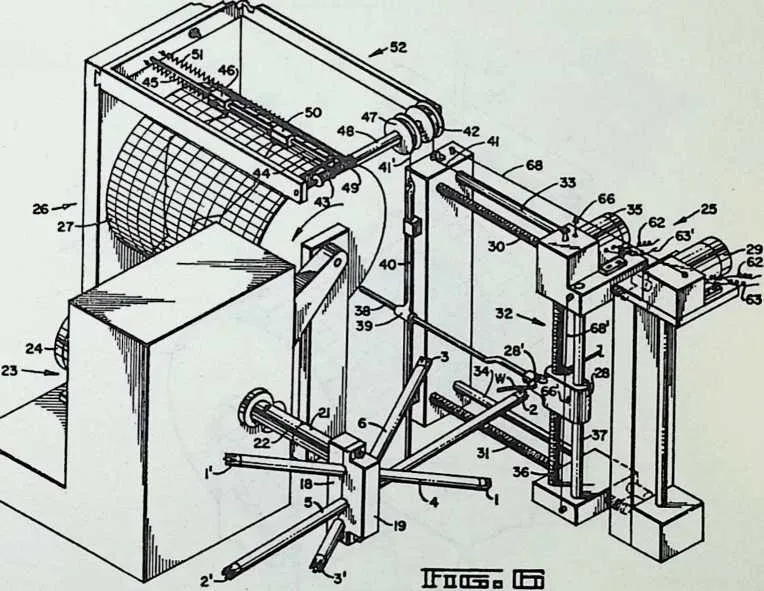
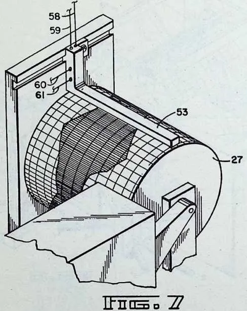
26 The isometric perspective of Figure 6 shows not only the spinner of Figure 4, but also the wire feeding means and means for producing relative movements between the rotating strut assembly and the wire feeding means, in combination with a programming control means. Figure 7 reproduces a portion of the same apparatus as it appears following removal of the stylus frame of the programmer and substitution of the photoelectric ‘‘playback’’ device.
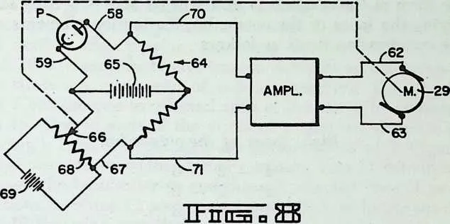
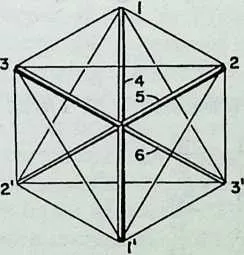
29 A diagram of the control circuit for one of the two motors of the wire feed control is furnished by Figure 8, while the diagram of Figure 9 illustrates the special case in which the truss component is a regular octahedron.
32 ITnnsoS]
33 Looking first at Figure 1, we see an octahedral truss component which has three compression struts 4,5 and 6, which are arranged along the three axes of the octahedron, 1--1', 2--2', and 3--3'. The upper ends of the compression struts 4, 5 and 6 lie in one plane and the lower ends lie in another plane below the first. The seemingly complex but truly simple form of the octahedral unit will be understood by identifying the faces of the octahedra, the tension elements and the compression struts as follows:
34 Eight faces of the octahedra:
36371-2-3 1' - 2' - 3'
38 1 - 2 - 3'
39 1' - 2 - 3
40 1--2' - 3
41 1 - 2' - 3'
42 1' - 2 - 3'
43 1' - 2' - 3
|
46Twelve tension |
47elements: |
|
501-2 |
511-2' |
|
522-3 |
531-3' |
|
543-1 |
552-3' |
|
561' - 2' |
572-1' |
|
582' - 3' |
593-1' |
|
603' - 1' |
613-2' |
68 Three compression struts:
69 From the foregoing tabulation of the truss elements, the student of this disclosure will appreciate the preponderance in tension elements over compression elements and the significant improvement thus obtained in the direction of utilization of the high tensile properties of the improved materials and alloys available today.
70 In the preferred construction shown, we have a three- dimensional truss component consisting of struts 4, 5 and 6 and flexible edge portions extending between ends of the struts, these being the twelve tension elements as listed above. The struts are comprised of tubular members. The fastenings 7 are secured to selected ends of the struts for connection to selected ends of the struts of similar components in forming a truss. Fastenings 7 are perforated as at 8, Figure 2, and are secured to the struts by tension wire 11 extending through the tubular struts and through selected ones of perforations 8. Wires 11 are stressed in tension, as by means of nuts 12 threaded onto their ends.
71 The fastenings may be made with flanges 9 in which are arcuate slots 10 for attachment to cladding sheets such as described in my patent aforesaid.
72 The wire W is attached to the ends of the struts in suitable manner, as by the means shown in Figure 3. Here a collar 13, with attaching flange 14 is secured to each end of the strut as by welding or brazing. Collar 13 is interiorly threaded and castellated to make tapered notches 15. These receive and position wire W as it is spun onto the strut complex. A locking ring 16 with notches 17 for engagement by a wrench is fastened into the end of collar 13 for clamping the wire into engagement with the bases of notches 15 wherever the wire lies. Notice that the wire crosses each end of each strut twice. Fastenings 7 are secured to selected ends of the struts after locking rings 16 have been set. Figure 1 shows a completed truss component with two such fastenings in place, in this instance at the ends of strut 4. Struts 5 and 6 will be secured to similar fastenings initially forming a part of adjacent components, and struts of adjacent components whose ends are not initially provided with such fastenings will be secured to fastenings 7 of the Figure 1 component as indicated at 4', 11', in Figure 1. The perforations 8 in the fastenings furnish a selective adjustment of the angular relationship between the struts (such as struts 4 and 4') of the interconnected components.
73 With reference to Figures 4-8,1 shall now describe a preferred form of apparatus for spinning the tension wire over the ends of the struts to make a three-dimensional truss component. This apparatus will be described in its particular application to the fabrication of a truss component of octahedral form having its eight triangular faces outlined by the tension wires of the complex. Three struts 4,5, and 6 extend between the three pairs of vertexes as has been described with reference to Figure 1. The apparatus comprises means for holding the struts 4, 5, and 6 in predetermined angular relation to one another to form a preliminary strut assembly. This means comprises clamping members 18 and 19 fixed to a hub 21 for attachment to shaft 22 of a device for rotating the strut assembly, such as a rotator 23 driven by motor 24. The apparatus further comprises means for feeding a wire W for attachment to the ends of the struts 4, 5, and 6, and means 25 for producing relative movements between the rotating strut assembly and the wire feeding means to bring the wire into engagement with first one strut end and then another, thus to form the flexible edge portions of the truss component.
74 Relative movements between the rotating strut assembly and wire feeding means are controlled by a ‘‘reader’’ drum 27, Figure 6, in which are stored data for successive relative positions of these parts of the apparatus, and a photoelectric sensor 53, Figure 7, which translates the stored data into controlled operation of the aforesaid relative movements in timed relation to rotation of the strut assembly.
75 In Figure 4, the strut clamp 18, 19 is shown ‘‘exploded,’’ i.e., with member 19 displaced to the right to allow removal of the completed truss component. Grooves 20 in member 19 are disposed in a predetermined angular relationship to one another and cooperate with complementary grooves in member 18 in determining the angular relationship between the several struts. In the particular construction shown, the rotator 23 may turn the strut assembly about the axis of shaft 22 at a constant speed, and will turn three revolutions to spin one octahedron. Reader drum 27 is driven by rotator 23 through a 3 : 1 chain drive (not shown) so as to turn one revolution to each three revolutions of the rotator. Thus each revolution of drum 27 can direct the movements of the wire guide 25 throughout the spinning of one complete truss component of octahedral form.
76 Wire leader 25 is capable of moving the guide 28 horizontally and vertically, or both simultaneously. Wire W passes through an aperture 28' in the guide 28 after being fed from a reel. As the wire is fed into the apparatus, it is placed under controlled tension, using for this purpose any of the known devices for tensioning feed wires. Horizontal movement of guide 28 is produced by a reversible motor 29 which is geared to screws 30 and 31, driving lead unit 32 horizontally. Shafts 33 and 34 serve to guide the horizontal movement. Vertical movement of guide 28 is produced by a reversible motor 35 which is geared to screw 36, 37 being a guide rod for such vertical movement. When motor 29 is operated for horizontal movement of guide 28, rod 38 fixed thereto slides through sleeve 39 so as not to produce any movement of the vertical rod 40. During this horizontal movement, wire 41, which is fixed at one end to lead unit 32, is wound or unwound on or from drum 42 fixed to a rotatable shaft which also carries spool 43. The wire 44 and spring 45 move a stylus unit 46 one way or the other to produce a line on the graph paper on drum 27. When vertical movement of guide 28 is produced, shaft 38 acts to raise or lower vertical rod 40 to wind or unwind wire 41' on or from reel 47 which is mounted on a shaft 48 connected to spool 49 on which is wound a wire connected to stylus unit 50 biased by a spring 51. The shaft 48 of spool 49 is hollow, and is concentric with the shaft for spool 43. Stylus 46 records a trace for horizontal movement, and stylus 50 a trace for vertical movement, of guide 28.
77 When setting up the control pattern on reader drum 27, the rotor motor 24 and leader motors 29 and 35 can be operated by manual switching (not shown) so as to bring the aperture 28' of guide 28 into the proper successive positions to connect the wire W to the respective ends of the struts 4, 5 and 6 as each in turn is presented to the wire leader. Errata and irregularities in the graph on reader drum 27 as produced during this manual pilot operation for a given design of truss unit can be straightened out on the graph by manual editing. Thereafter the area between the two traces may be blacked in as illustrated in Figure 7 to complete the photoelectric playback pattern.
78 Once the data for the desired design of truss component have been stored in the manner described, stylus frame 52 is removed and the wires 41 and 41' disconnected. If desired, the rods 38 and 40 also may be removed. Then the photoelectric sensor 53 is installed over the drum 27 in the manner shown in Figure 7 to give orders to the leader motors 29 and 35 according to variation of light in the drum pattern. It may be observed at this point that the graph sheet upon which the data are stored is removable so that the spinning program for each different design of truss component can be filed for later use as needed. Thus a program for each design of component, once recorded, need not be re-created. Although I have described one desirable method of programming according to which manual settings are recorded from a prototype setup, it will be understood that other methods of programming are feasible. For example, the programs can be calculated through mathematical or graphic solution, and with the aid of conventional computers as desired.
79 A playback control for the lead motors 29 and 35 is illustrated in Figure 8. This is a diagram for one of the two photocell and motor hook-ups, here considered to be the one which controls operation of motor 29 for producing horizontal movements of wire guide 28. A photocell P in the sensor 53 provides a voltage between a pair of leads 58 and 59 connected in abridge circuit 64 containing conventional resistors, as shown, and energized by a source 65 of direct current. The voltage output from photocell P varies in accordance with variations in the outline of the trace defined by the edge of the dark area on the playback drum adjacent the sensor 53. The voltage appearing between contact 66 and lead 67 of the bridge 64 varies in accordance with the horizontal position of die aperture of wire guide 28, Figure 6. Contact 66 may be mounted on the horizontally movable wire lead unit 32, as shown, and has a sliding contact with a resistance wire 68 which is attached to insulator supports on fixed portions of the leader 25. The resistance wire 68 is energized by a direct current source 69, Figure 8, to form a potentiometer.
80 When the wire guide 28 is located to one side or the other of the desired position as directed by the trace, an unbalance voltage occurs across bridge 64. This unbalance voltage is fed through a pair of leads 70 and 71 into an amplifier. The output from the amplifier is supplied to motor 29 through connections 62 and 63, moving the wire guide 28 toward its desired position as directed by the trace. The direction of the direct current produced in the leads 70 and 71 by the unbalance voltage will be determined in accordance with the position of the wire guide whether to one side or the other of its correct position at any particular moment in the programmed spinning cycle. The motor will thus be operated in a direction determined by the direction of the current produced by the unbalance voltage. When the wire guide reaches its correct position, the bridge becomes balanced, and the voltage across the leads 70,71 drops to zero, stopping the motor 29.
81 Similarly, for control of the operation of motor 35 to produce vertical movements of wire guide 28, there is a contact 66' mounted upon the wire guide 28 so as to follow its vertical movements. Contact 66' has sliding engagement with a resistance wire 68' attached to insulator supports on horizontally movable portions of the lead unit 32. Contact 66' and resistance wire 68' are included in a vertical control circuit corresponding to that shown in Figure 8. Contact 66', Figure 6, corresponds to contact 66, and resistance wire 68' corresponds to resistance wire 68. The output from the vertical control circuit is supplied through connections 62' and 63' to the motor 35.
82 The design of the particular component to be fabricated will determine the form of the clamping members 18, 19, and the disposition of the complementary grooves 20 in such members. A series of different clamp designs may be provided for this purpose or, if desired, the clamps may be made adjustable so that the angular dispositions of the grooves relative to one another can be varied at will. In either case, the means for holding the struts in any one of a number of predetermined angular relations to one another is thus adjustable.
83 In addition to the means for holding the struts in predetermined angular relation, I have provided means for indexing the relation between the struts to predetermine the relative dispositions of the ends of the struts for a given angular relation. For this purpose, my preferred form of apparatus includes an indexing fixture 54, Figure 4, having recesses 55 to receive the ends of the struts and properly position them within the clamps 18, 19. Either by regulating the relative depths of the recesses 55 in the fixtures 54 or by predetermining the angular disposition of the fixture while the struts are being placed in the clamps, the extent to which each strut projects to one side or the other of the clamp is predetermined. Thus angular disposition is governed by the clamp, and lengthwise position within the clamp is determined by the fixture 54. A series of fixture 54 of differing patterns may be used interchangeably to secure a variety of designs of truss components, each being related to a given set of clamps 18, 19, or to a given adjustment in the case of an adjustable clamp. Alternatively, fixture 54 may be provided with suitable adjusting means for altering the relative positions of the ends of the struts. The positions of the recesses 55 in the fixture may be predetermined by mathematical or graphic solution, or with the use of a computer, as desired. My invention is not concerned with the computation of the form of the truss component, as the apparatus and method can be used regardless of the particular design of component. Following indexing and clamping of the struts, indexing fixture 54 is removed, and the operation of spinning the wire W onto the strut ends can begin.
84 When using the octahedral form of truss component described and shown, it is possible to spin a wire around the six ends of the criss-crossed struts without reversing the direction of rotation of the strut assembly during the process. One feasible order of accomplishing this is to begin at vertex 2, locking the end of the wire to this vertex, carrying the wire from vertex 2 to vertex 1, thence to vertex 2', etc., according to the following sequence:
85 Order of spinning:
- 2.
- 1
- 1.
- 2' 2' - 1' 1' - 3
- 3.
- 1
- 1.
- 3' 3' - 2
- 2.
- 3
- 3.
- 2' 2' - 3' 3' - 1' 1' - 2
90 This order of spinning will be found suitable when the rotator is turned in the direction of the arrows shown around the shaft 22 in figures 4 and 6. A reverse order might be followed. As another order of spinning well suited to a regular octahedral unit having eight equilateral triangular faces as represented in the diagram of Figure 9,1 may proceed as follows: set up the three struts in the clamp 18, 19; then, instead of rotating about the axis of hub 21 (Figure 4), set up the strut 1—1' in arbors for rotation about the axis of strut 1—1' and spin in the order:
- 2.
- 3
- 3.
- 2' 2' - 3' 3' - 2
92 Then set up with strut 2—2' in arbors and, rotating about axis 2—2', spin:
93 1-3
95963-1' 1' - 3' 3' - 1
97 Finally, place strut 3—3' in the arbors and spin:
- 1.
- 2' 2' - 1' 1' - 2
- 2.
- 1
99 This method will also work for spinning irregular octahedral units so long as the wire feed is moved to and fro in the manner described above. It will be appreciated, however, that in the case of the regular, or substantially regular, octahedral unit the movements and apparatus can be simplified for the reason that the step of producing relative movements between the rotating strut assembly and the wire feed can be performed by rotating the strut assembly without appreciable movement of the wire feed, if any.
100 I call attention to the fact that the wire leader 25 comprises means for moving the wire guide 28 to and fro in different directions of linear movement to produce two-dimensional movements of the guide, the control means serving to control such two-dimensional movements of the wire guide in timed relation to rotation of the strut assembly to produce the three-dimensional components. Movements of die wire guide 28 are not necessarily restricted to the horizontal and vertical as shown in Figure 6, as it will be appreciated that the wire feed can be disposed in any position relative to the rotating strut assembly which will serve to bring the guide 28 into proximity with each strut end successively.
101 After completion of spinning, and the application of the locking rings or collars 16, Figure 3, clamp 18, 19 is opened and the truss component will be self supporting. If desired, spacer member 56, Figure 5, may be inserted between the criss-crossed portions of the struts and a tie 57 applied around the struts and spacer.