
11 The Structural Morphology of Basic Polyhedra
2Tore Wester
11.1 INTRODUCTION
3The fascinating world of polyhedra has a long and diverse history. These archetypical geometrical configurations have influenced numerous aspects of art and science. When introduced in a theme or subject, polyhedra seem to be the carriers of a strange and satisfying basic order to the subject, for example, Plato’s pythagorean cosmology, Kepler’s planet shells, the crystal symmetry groups, and so forth. Different fields, such as crystallography, engineering, mathematics, astronomy, architecture, art, cosmology, astrology, and religious and divine orders, have all been affected by the scientific and philosophical conceptual content of polyhedra.
4 Polyhedra almost always play a role in architecture as architects think in terms of plane facets such as walls, roofs, ceilings, facades, and so on, combined to form spatial configurations, making up what are basically nothing other than clusters of polyhedra! Unfortunately, the connection with polyhedra is often unperceived and unreflected, and the cube seems to be the absolute favorite. This book is a serious and qualified attempt to challenge this
5 Beyond the Cube: The Architecture of Space Frames and Polyhedra, edited by J. Francois Gabriel □
6 301
7 ISBN 0–471–12261–0 © 1997 John Wiley & Sons, Inc.
910unfortunate situation. Moreover, the lattice structure, based on bars and nodes in the simple rigid triangular configuration, has been considered as the only structural archetype. This defines the triangulated members of the regular polyhedra—the tetrahedron, octahedron, and icosahedron—as the only inherently rigid ones, leaving the nontriangulated—the cube and the dodecahedron—as incomplete and inferior structural configurations.
11 This chapter will try to bring a satisfactory order to the concept of basic
12 Figure 11.1
13 Figure 11.2
15 BOX 1: Expressions and Definitions
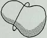
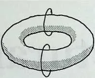
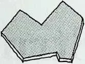
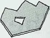
1718A simple polyhedron is a one-connected polyhedron where all facets are planar and one connected. Connectivity is the maximum number of closed chains required to divide the polyhedron into two separate parts; that is, a ball is one connected, whereas a torus is two connected (Figure 11.1). A facet that has a boundary consisting of only one loop is one connected, whereas a facet with a single hole (i.e., two loops) is two connected (Figure 11.2). A simple polyhedron may be convex or nonconvex.
19Basic polyhedra, in the present context, mean polyhedra that might be fixed to the ground, and perhaps with some elements or links removed or added, but geometrically based on one or more simple polyhedra.
20Elements are plates (facets) or nodes (points), whereas links (lines) are their connectors (shear lines or bars). Linking is a list of information concerning which elements are finked together. The linking of a node is the information concerning which other nodes the node is connected to (by bars). In the case of plates, linking is the information concerning which of the neighboring plates the plate is connected to (by shear lines). In order to define a plate based on the plane of the plate and its linking, the links must be listed in the required order as when walking around the boundary of the plate.
21The valency (Figure 11.3) of an element (plate or node) is its number of links (shear lines or bars). Valency, linking, and connectivity are all topological information. Topological information is information about geometric values that are counted but not measured. Metric
22
geometry is, on the other hand, information about positions given by coordinates, lengths, angles, and so on, that is, all characteristics that can be measured. Mathematically, topology is described by integers (e.g., 1, 5, 112, etc.) and metric geometry by real numbers (e.g., 4.37, 5.00001, 199.998, etc.).
23 structures in terms of their relationship to the Platonic polyhedra. In order to understand why this structural order in space has not been described a long time ago, it is necessary to take a brief look at the history of the theory of structures.
24 Brief History of Polyhedra as Structures
25 The history of the theory of basic structures related to polyhedra and topology is short and uncomplicated.
26 The French bridge and road engineer, but primarily mathematician, Augustin-Louis Cauchy (1789–1833) described in 1813* the rigidity of arbitrary convex polyhedra from a purely geometrical viewpoint. This means that he did not consider the equilibrium and the type of forces inherent in their geometry.
27 A few years later, in 1837, the German professor of astronomy August Ferdinand Mobius (1790–1868), inventor of the famous nonorientable Mobius strip in 1858, made what is probably the first statical description of polyhedra as structural objects. In his textbook on statics,2 Mobius states, probably for the first time ever, the minimal number of bars (BA) required to
28 BOX 2: Expressions and Definitions
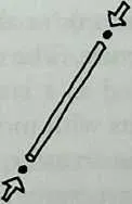
3031A polyhedral lattice structure is composed of nodes (polyhedral vertices) that are linked by bars (polyhedral edges). The bars are hinged to the nodes; that is, it is not possible to transfer bending moments between bars. The nodes distribute axial forces—tension or compression—between bars (Figure 11.4).
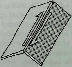
32A polyhedral plate structure is composed of flat, rigid-in-plane plates (polyhedral facets) that are hinged together along shear lines (polyhedral edges) as lines of intersection between plates. The plates distribute the forces between the shear lines. In plate action only shear forces are transferred across the shear lines. A shear force is a pair of oppositely directed parallel forces of equal magnitude and with zero distance between them, acting between two plates that are interconnected by a shear line (Figure 11.5). The plates distribute the forces as shear forces among the shear lines.
33In solving the static equilibrium, each of the elements (a node or a plate) represents three equations, whereas every link (a bar or a shear line) represents one unknown.
35 BOX 3: Expressions and Definitions
3738Two objects are dual if they are based on the same information, but this information is interpreted in a different way. A dttal transformation implies a switch between the interpretation of data. Further, a dual transformation must preserve all data, and the dual of the dual must be the original. It may be described as a kind of mirror image, two sides of the same thing, and so forth.
39Whereas duality is a technical expression, dualism is a philosophical term often used as a contradiction to monism and related to two opposites (good/bad, yin/yang, closed/open, feminine/masculine, day/night, etc.). In the actual context, duality in many ways appears to approach dualism. In three-dimensional geometry dualism is related to the substitution of vertices with planes. After a dual transformation the valency, linking, and connectivity remain the same, but the element type has changed, as nodes and plates are exchanged.
40Gaussian curvature: The two principal curvatures at a point on a surface may have either equal signs if the centers of curvature are located on the same side of the surface (Figure 11.6) or opposite signs if the centers of curvature are on different sides of the surface (Figure 11.7). If the signs are equal, then the Gaussian curvature is positive because +(+) = + and -(-) = + and negative if they are different because -(+) = -. Positive Gaussian curvature is also called synclastic, elliptic, or dome shaped, whereas negative Gaussian curvature is called anticlastic, hyperbolic, or saddle shaped. If one or both of the principal curvatures are 0, then the Gaussian curvature is 0 because 0 times anything is 0.
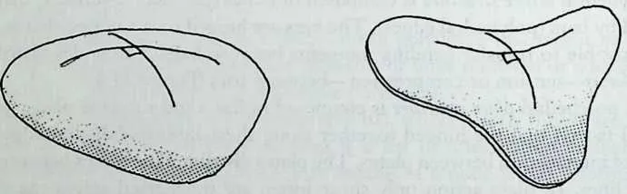
42 Figure 11.6 Figure 11.7
43 (Figures courtesy of Ola Wedebrunn.)
44 stabilize a certain number of nodes (NO)' BA = 3NO -6 (this should therefore rightly be called Mobius’ theorem of rigidity). By combining the important theorem of Euler (1707–1783) for polyhedra consisting of vertices, facets, and edges (V+ F = E + 2), Mobius also proved that the number of equations and the number of unknowns are equal (neutral configuration) for any triangulated simple polyhedron regarded as a pure lattice structure. The same neutrality holds for an arbitrary simple polyhedron regarded as a lattice structure supplied with rigid-in-plane plates filling out all facets with more than three edges. In this case rigidity is achieved by means of the transfer of forces parallel to the bars between the plates and the lattice structure. However, it is remarkable and quite surprising that he did not describe the bar-and-node free system: pure plate action and its theorem of rigidity.
45 Mobius wrote a whole chapter,3 Von der unendlich kleinen Beweglichkeit
46 BOX 4: Expressions and Definitions
4849Neutrality (or kinematical neutrality): A structure is neutral if it is just rigid; that is, it has no redundancy. It becomes movable if a single link (bar or shear line) is removed from the structure. A neutral structure is statically and geometrically determinate; that is, it is in equilibrium by static considerations alone and complies with the theorems on the minimum requirements for rigidity—and it may be built and determined geometrically with no constraints on the metrical values.
50Rigidity, stability: A structure is rigid or stable if it has enough links (bars or shear lines) to fix all elements (nodes or plates) and they are arranged geometrically and topologically in such a way that static equilibrium can be achieved; that is, the static equations can be solved. A rigid or stable structure may be sensitive (see below). In the case of a critical situation, it is called flexible. Stability is used here as a kinematic—not an elastic—property.
51Movability, flexibility: If a structure has too few links (bars or shear lines) to fix the elements (nodes or plates), it is movable or unstable. If the links in a rigid structure change length or position, the structure may become movable. If the geometry of a rigid structure is changed, it may go into a critical (flexible) or a near-critical (sensitive) form. In these cases the static equations give no solutions or give unreliable solutions.
52Sensitivity: If a structure is in a near-critical state, a number of internal forces become very large even for moderate external loadings. Hence the deflections will be large and the structure feels movable. This will often happen under very particular external load combinations, whereas it is perfectly rigid for other loading cases.
53Redundancy: If a structure has more links (bars or shear lines) than are needed for rigidity, it is redundant. If a redundant structure has a special geometry and/or a special linking, it may be movable, flexible, or sensitive. The redundancy number indicates the number of links—but not which specific ones—that may be removed without changing the stability situation.
54 (On the Infinitesimal Movability), where he explains that there are special critical cases where a plane neutral lattice structure (the equation for the plane two-dimensional lattice, BA = 2NO -3, was also first stated by Mobius) is not absolutely rigid. The statical characteristic is that the determinant of the equilibrium equations approaches 0; hence the magnitude of the forces approaches 00. Furthermore, he describes methods to create these critical configurations as follows:
- Make a plane neutral lattice structure movable by removing one bar.
- Choose two nodes that can be moved relative to each other.
- The distance between these two nodes has a maximum and a minimum.
- Place the previously removed bar (with its new appropriate length) in one of these two extreme positions and the system becomes flexible.
55 This method also works sometimes for creating flexible three-dimensional structures.
56 Unfortunately, Mobius’ work on statics has been dormant for many years and he rarely gets credit for his important work. A notable exception is in the classical work by Stephen P. Timoshenko.4 Although Mobius’ theorems were rediscovered several years later by a number of prominent engineers, it appears that, for many years, very few discoveries regarding polyhedral structures were made.
57 In the field of flexibility, R. Bricard5 constructed, in 1897, flexible but selfintersecting octahedra, and in recent years Robert Connelly6 has, on a purely geometrical basis, found true non-self-intersecting and flexible polyhedra—also based on the octahedron. A very interesting paper by Jorgen Nielsen7 shows unexpected instability, argued on the basis of static equilibrium, for some combined plate and lattice structures that are shaped as step pyramids.
58 The historical work on polyhedral structures by Mobius has three of the four necessary ingredients for the full description of the basic structural morphology of polyhedra, namely, bars, nodes, and plates, but it lacks shear fines as a unique structural member. Probably because Mobius did not consider plate action as being just as basic as lattice action, the inherent structural activity of polyhedra has ever since been based on bars and nodes only. Accordingly, only three of the five Platonic solids appear inherently rigid—namely, all the triangulated ones—the tetrahedron, octahedron, and icosahedron, whereas the two remaining, the cube and the dodecahedron, are basically movable, that is, incomplete as rigid structures (Figure 11.8). In order to make them rigid, one can either add extra bars or plates or introduce bending stiffness in the bars and nodes.
59 This cosmology of structural action has been common knowledge and supported very actively by, for instance, R. Buckminster Fuller and many others. Of course, this situation is unsatisfactory, as the five Platonic polyhedra in so many other aspects form an archetypical entirety. This entirety can easily be achieved by using Mobius’ considerations about rigid-in-plane plates by intersecting them directly along what become the shear lines and arranging them as polyhedral structures and—importantly—avoiding bar-and-node action similarly to the way that pure lattice polyhedra avoid plate action when
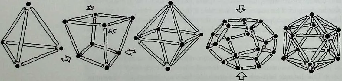
6263Figure 11.8 The three rigid and the two movable regular polyhedra as pure lattice structures. (Courtesy of Ola Wedebrunn.)
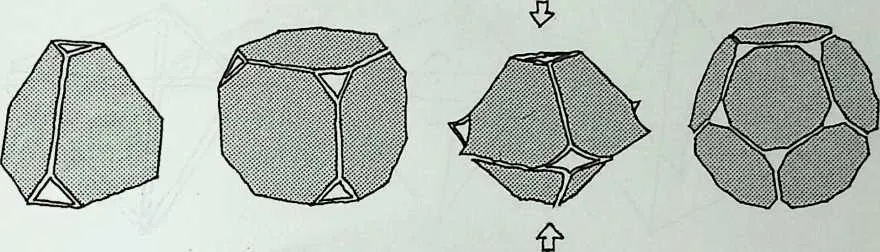
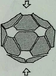
65 Figure 11.9 The three rigid and the two movable regular polyhedra as pure plate structures. Note that vertices are removed in order to avoid nodal (i.e., lattice) action. (Courtesy of Ola Wedebrunn.)
66 triangulated. The way of avoiding lattice action, hence isolating plate action in a simple polyhedron, is to require that all vertices are trivalent, which is the dual of the pattern for triangles, equal to trivalent facets. The trivalent vertex is topologically significant for the cube, the dodecahedron, and the tetrahedron but not for the octahedron and the icosahedron, which are unstable as plate structures (Figure 11.9). Note that all vertices are removed in order to avoid lattice action, hence isolating plate action. The stabilizing forces are shear forces transferred along the shear lines.
67 As Mobius’ theorem for pure lattice structures, when using geometrical symbols, is E = 3 V -6, the corresponding theorem for pure plate action can easily be found8 to be E = 3F -6, which, combined with Euler’s theorem for polyhedra, results in 2E = 3 the geometrical requirement of trivalent vertices for structurally neutral pure plate action for simple polyhedra. It is seen that if V and F are exchanged we shift between the two theorems of rigidity—which means a shift between geometrical duals, because V and F are interchangeable, whereas E remains unchanged in Euler’s theorem V + F = E + 2. With structural symbols the theorem of rigidity for plate action will therefore be SL = 3 x PL -6, where SL and PL are, respectively, the number of shear fines and plates. This is seen to be the dual to Mobius’ theorem of rigidity for lattice structures: BA = ?>NO - 6.
68 Now the five Platonic polyhedra are all equally basic as structural objects. They are divided into two groups of three (Figure 11.10), where the tetrahedron is present in both groups, following exacdy the pattern for geometrical duality. The trivalent facet has the same structural impact for lattice action as the trivalent vertex has for plate action. This leads to the principle that topology and rigidity (with reservation for the previously mentioned critical situations) for simple polyhedra are the geometrical and structural expressions of the same thing and, at the same time, they are complementary.
69 Even though these considerations put statics in a satisfactory connection with polyhedra, their importance would have been very limited if the previously mentioned principles were restricted to the five Platonic solids. Fortunately, these static/geometric principles, based on the replacement of lattice nodes with plates and node-connecting bars with plate-intersecting shear fines, are valid, in general, for any arbitrary polyhedron—and any cluster of
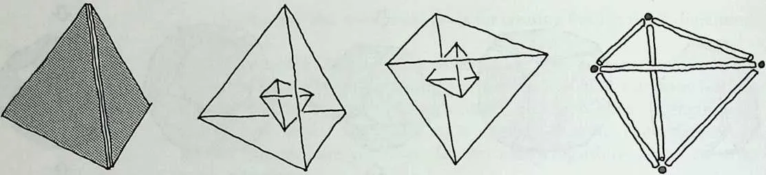
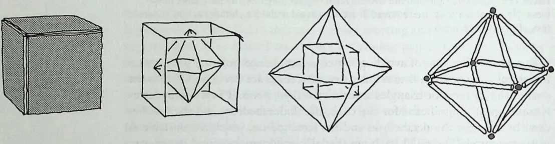
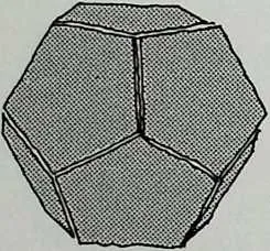
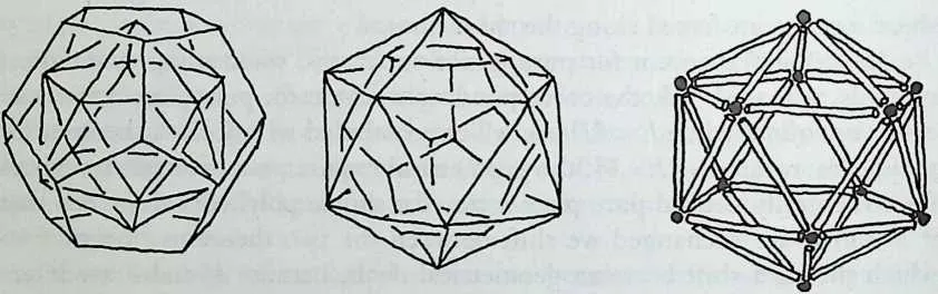
71 Figure 11.10 The basic structural behavior of the regular polyhedra follows exactly the geometrical duality: One of the dual versions is rigid by plate action, whereas the other is rigid by lattice action. (Courtesy of Ola Wedebrunn.)
72 polyhedra—independent of connectivity, linking, convexity, and so forth. For any given three-dimensional pure lattice structure, there always exists a dual pure plate structure, and vice versa, but, of course, it may not be suitable as a structure for architecture—or anything else.
73 The trivalent vertex and trivalent facet are geometrical extremes (Figure 11.11) as no plane facet can have fewer edges than three and no vertex in three-dimensional space can have fewer than three adjacent edges. Between these two extremes there are countless possibilities for polyhedra with facets and vertices with different valencies. These not fully trivalent, simple polyhedra are movable either as pure plate structures or as pure lattice structures. They may be regarded as lattice structures stabilized by fill-in plates as considered by Mobius, or they may be regarded as two independent movable structural types (Figure 11.12) stabilized by the transfer of forces between the equally positioned bars and shear fines. I have suggested that these forces that
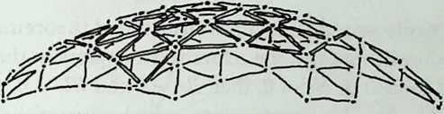
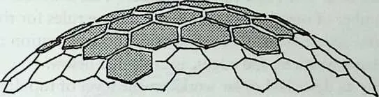
76 Figure 11.11 The triva I ent vertex and the equivalent facet are both geometrical extremes and form the geometric pattern synonymous with pure plate and lattice action. (Courtesy of Ola Wedebrunn.)
77 are working in between the two pure structural types are called buffer forces.9 These considerations give rise to the general theorem for the necessary requirement for rigid, simple polyhedra10
78 B4+S£+BL/ = 3x(/V0+W)-6
79 where BA, SL, BU, NO, and PL refer to the number of bars, shear lines, buffer forces, nodes, and plates, respectively. As all three variables on the left-hand side of the equation refer to edges, the equivalence of the general requirement as being identical to Euler’s theorem for polyhedra, E = E+ F -2, is easily rec-
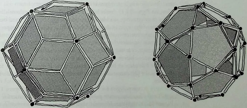
81 Figure 11.12 The rhombic triacontahedron (left) and its dual, the icosidodecahedron (right), are both unstable as pure lattice and pure plate structures. However, if they are constructed so that both structural actions are possible at the same time and if buffer forces can be transferred between equally positioned bars and shear lines, they then become rigid. Note that trivalent nodes and equivalent plates may be removed without affecting the rigidity. (Courtesy of Ola Wedebrunn.)
82 ognized. It is also easily seen that the previously stated theorems for pure lattice and plate action will appear if the relevant parameters in the general theorem are required to be 0 (if NO = 0, then BA = 0 and BU = 0, and if PL = 0, then SL = 0 and 517= 0). This interpretation, which equates the level of plate and lattice action, has the advantage of following the concept of geometrical duality. The close topology-rigidity connection between the duals forms a promising basis of a ‘‘form-and-force language.’’ This is because it is possible to set up a number of surprisingly simple and unique rules for the description of the structural action of any three-dimensional configuration that is a combination of planes, vertices, and edges, as explained below.
83 The duality as described so far works on the level of topology and rigidity. This level of understanding is the most important for the architectural, morphological, and conceptual aspects: choice of structural types, choice of faceting, where to open up the building and where to close it, choice of structural material, and so forth. It does not, however, condition the exact shape, size, and form of facets and so on. However, the dual transformation concept may be extended to the level of metric geometry and statics.
84 This transformation is based on simple but essential and fundamental considerations:
- Let the upper left of Figure 11.13 be an w-valent node in a three-dimensional lattice structure. Then Figure 11.13, upper center, shows the force vectors acting on this node and Figure 11.13, right, is the corresponding three-dimensional force vector polygon, which means that the force vectors are arranged unidirected and one after another in correct direction and magnitude. If the vector polygon forms a closed loop, then this is the necessary and sufficient requirement for this node to be in static equilibrium. If all nodes in the lattice structure are in equilibrium, then the whole structure is in equilibrium.
- Now, let Figure 11.13, lower left, be an n-valent plate in a three-dimensional plate structure, and let a point (the origin) be positioned outside the plane of the plate. In this case Figure 11.13, upper center, represents the moment vectors acting on the origin.11 Figure 11.13, right, shows the three-dimensional moment vector polygon derived from the moment vectors acting on the origin. If this is unidirected and forms a closed loop, as before, then this is the necessary and sufficient requirement for this plate to be in static equilibrium. If this is the case for all plates in the plate structure, then the whole structure is in static equilibrium.
- If a force vector polygon for a node in a lattice structure (Figure 11.13, right) and a moment vector polygon for a plate in a plate structure (also Figure 11.13, right) are identical, then the system of force vectors (Figure 11.13, upper center) is identical to the system of moment vectors (also Figure 11.13, upper center). It is significant that it is not possible to judge from the system of vectors and its polygon if it represents the equilibrium of a plate or a node—this is up to you. This means that if
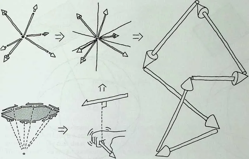
86 Figure 11.13 The equilibrium offerees on a node and the equilibrium of moments created by forces on a plane plate around a reference point (the origin) can be required to be equal. This forms the basic static requirement for structural duality. (Courtesy of Ola Wedebrunn.)
8889you do statical calculations on a three-dimensional lattice structure, you calculate a plate structure, of which form you have absolutely no idea, at the same time—quite an interesting thought. It is also evident that the two systems cannot be mixed as the equilibrium requires the vector polygon to consist entirely of either force vectors or moment vectors.
- If there is a transformation method that assures that the force vector and moment vector systems are identical, then we can switch between the two systems.
- The force vector and moment vector systems can be made identical if the transformation of a node creates a plane plate, if a bar creates a line of intersection between plates (shear line), and if the force vector and the corresponding moment vector are always parallel. These simple requirements are fulfilled if the structures are transformed by the geometrical relation called polar reciprocation as described by Cundy and Rollet.12 A thorough explanation of the particular geometry inherent in polar reciprocation is given by Wenninger, based on his correspondence with Cundy.13
90 Polar reciprocation relates the location of a vertex and its dual plane simply as follows (Figure 11.14):
- The method requires a reference point, chosen as the origin for simplicity.
- The vertex is located on the line from the origin perpendicular to the plane.
- The distance from the origin to the vertex multiplied by the distance from the origin to the plane is a chosen constant. If this constant is chosen as 1, the two distances are reciprocal.
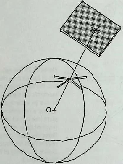
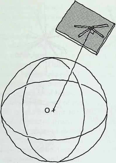
92 Figure 11.14 Dual transformation by polar reciprocation. (Courtesy of Ola Wedebrunn.)
93 Figure 11.15 Direct dual transformation. (Courtesy of Ola Wedebrunn.)
94 This transforms the metric geometrical information between planes and vertices, whereas the topological information, that is, the linking of the vertices and the planes, respectively, remains unchanged.
95 A similar transformation, called direct transformation (Figure 11.15), simply changes the interpretation of the geometrical data between nodes and plates, and vice versa. This means that it is identical to polar reciprocation except that the distance between the elements is not reciprocated. Direct transformation maintains the valency of the elements, as does polar reciprocation, but not the statics. Polar reciprocation and direct transformation may be executed repeatedly one after the other, eventually in combination with changes in the position of the origin between the transformations. This combination makes a powerful tool for computerized methods for form finding of structures, not least because they relate architecturally very significant and different geometries—without changing the topology.
96 The polar reciprocation method proves to be as valid as the transformation method for structural duality for the following reasons:
- It satisfies the requirements of the topological duality as shown in Figure 11.10.
- There exists a line through the origin that intersects both the line that includes the bar and the line that includes the dual shear line. Furthermore, these three lines are perpendicular to each other (Figure 11.16). This quality implies that the moment vector will always be parallel to the corresponding force vector of the dual structure.
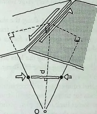
98 Figure 11.16 The perpendicular dual nature of geometry and forces: The line through the origin intersects both the action line for the axial force (which includes the bar) and the action line for the dual shear force (which includes the edge between the plates). These three lines are perpendicularto each other. (Courtesy of Ola Wedebrunn.)
99 The transformation factor between the magnitude of the bar force and the corresponding plate force in the dual structure is simply the actual distance d from the origin to the shear tine, because the bar force is required to be equal to the force in the shear line times its distance to the origin. The elastic properties are dually transformed14 by the factor dr. These transformations are very suitable for computers.
100 The preceding explanation is the extremely simple verification of the existence of structural duality. The static and elastic equations for dual structures are outside the scope of this chapter, but can be studied in the author’s paper.15
101 The procedure for the creation of dual structures will then be as follows:
- Move your structure in space so you have the origin where you want it.
- Perform a polar reciprocation. If the initial structure is a lattice structure, then the definition of which part of the plane should be materialized as a plate is a free choice and does not affect the statics, except that part of all the shear lines connected to this plate must be part of the materialized plate. Of course, the chosen geometry for the plate must enable the plate to be rigid in plane. Often it is practical that the shear lines define the boundaries of the plates.
- All forces are transformed as explained previously.
102 A static calculation of a statically determinate plate structure can be executed as follows:
- Transform the initial plate structure to its dual lattice structure. Any point of origin is possible, so you do not need to move the structure, unless the origin is very close to the plane of one of the plates. If the origin is too close to the plane of the plate, this will result in a computation that includes very small and very large numbers, which may create inaccuracy in the results.
- Transfer all external loadings to act along the shear lines. For example, loads acting perpendicular to the plates can be transferred to the vertices by bending as in slabs, and these vertex forces can be resolved in the directions of the shear lines.
- The dual external loads acting along the bars are determined by multiplying the external loads acting along the shear lines by the distance d from the origin to the actual shear line.
- Compute the internal equilibrium of forces in all bars by a conventional computer program for three-dimensional structural design.
- Transform the bar forces back to the plate structure as shear forces by dividing the bar forces by the same d used previously.
103 GEOMETRICAL QUALITIES OF DUAL STRUCTURES
104 Using the polar reciprocation method, the following qualities of dual structures can be identified:
- The dual of an w-valent node is an 72-valent plate, and vice versa; see Figure 11.3.
- There exists a line through the origin that is perpendicular to both a bar and its dual shear line and this bar and shear line are perpendicular to each other (Figure 11.16).
- There is a certain distance from the origin where a node is part of the dual plane.
- The origin can never be positioned in between a node and the dual plane.
- Polar reciprocation cannot be executed if the origin coincides with a node, as the dual plane will be infinitely far away in any direction.
- Polar reciprocation cannot be executed if the origin is part of the plane of a plate, as the dual node will be infinitely far away in the direction of the axis through the origin and perpendicular to the plane.
- Polar reciprocation cannot be executed if the origin is part of a bar, as the dual shear line will be infinitely far away and the plates it should connect would be parallel, hence never intersecting.
- A node close to the origin will, after polar reciprocation, produce a plate far from the origin, and vice versa, as the product of the two distances is a constant; that is, if the initial is very near to the origin, then the dual will be very far from the origin. The near to the for is an inherent dual quality.
- The sign of Gaussian curvature remains unchanged during polar reciprocation. A saddle shape remains a saddle shape and a dome shape remains a dome shape.
- Although the facets of a triangulated surface give no information about the sign of the Gaussian curvature for the main shape, the dual facets
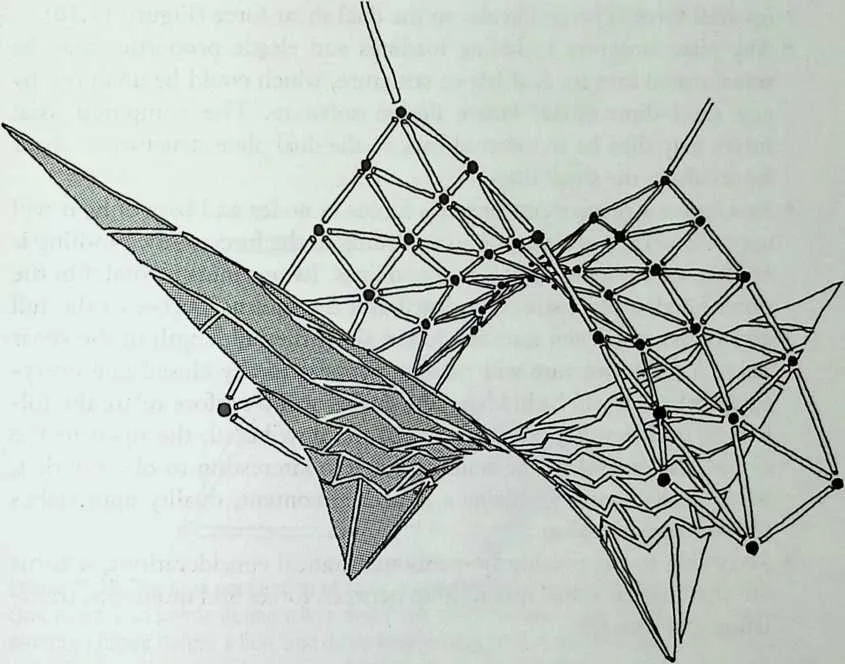
107108Figure 11.17 Each individual plate in a trivalent polyhedral structure is convex if the Gaussian curvature of the main shape is positive—and nonconvex if the curvature is negative. A triangular mesh in a lattice structure does not reveal the sign of the Gaussian curvature. (Courtesy of Ola Wedebrunn.)
109turn out to be convex for positive Gaussian curvature and nonconvex for negative curvature; see Figure 11.17. A plate in a pure plate polyhedron may reveal the curvature of the main shape of which it is a part.
110 STRUCTURAL QUALITIES OF DUALS
- The bar in a lattice structure connects hinged nodes and transmits axial forces, whereas the dual plate structure transmits shear forces across the hinged intersections between plates.
- Bars, shear lines, nodes, and plates are basically bending moment free; that is, they are surface-active membrane structures. Bending moments in bars (e.g., beams) and plates (e.g., slabs) are secondary to the lattice and plate action. Bending may be used in transferring and resolving the external loads into the plate-active or lattice-active surface.
- The statical determinacy (i.e., redundancy) does not change during a dual transformation.
- All static and elastic information is preserved after a dual transformation.
- An axial force is perpendicular to the dual shear force (Figure 11.16).
- Any plate structure including loadings and elastic properties may be transformed into its dual lattice structure, which could be analyzed by any three-dimensional lattice design software. The computed axial forces may then be transferred back to the dual plate structure as shear forces along the shear lines.
- As a lattice structure concentrates forces in nodes and bars only, it will appear open if it is materialized according to the forces only. Nothing is hidden behind theoretical points and lines. Its openness is total. On the other hand, a plate structure distributes the internal forces to the full area of the plates and transfers forces along the full length of the shear lines. A plate structure will therefore appear totally closed and everything behind it will be hidden. The duality will therefore relate the following qualities: the concentrated to the distributed, the open to the closed, the opaque to the transparent. It is interesting to observe that, when pure geometry obtains a structural content, duality approaches the concept of dualism.
- According to the previously mentioned statical considerations, it turns out that there is a dual relationship between forces and moments, translation and rotation.
111 THE STRUCTURAL MORPHOLOGY OF POLYHEDRA AS ARCHITECTURAL OBJECTS
112 Visually Based Structural Analysis and Design
113 One of the most fascinating qualities of plate-lattice duality is that it brings a unity to the concept of basic structures. The structural action of polyhedra is so closely and uniquely related to the geometry of polyhedra that they are as one. We have seen that the structural issue of rigidity may be solved either in a purely geometrical or in a statical way, which appear to be complementary. Plate and lattice action seems in this context to be as two sides of the same coin. They form two structural archetypes, which, in an antagonistic way, do not need each other, but together give a full and complementary understanding of basic structures and their interaction with geometry. They indicate that nodes and plates have equal status as main elements in structures, defined in exactly the same metric geometrical way. Bars and shear lines are the connecting links, defined by the topological information of their linking. Just as the geometry of the five Platonic polyhedra can be regarded as two groups with three in each, related by duality, statics fits exactly into the same pattern.
114 Traditionally, we consider zero-dimensional points as basic geometrical entities and then define the one-dimensional line as a direct connection between any two of them (which do not coincide), while a two-dimensional plane is defined by any three points (which are not collinear). However, in three-dimensional space we may use an alternative definition: We may introduce the two-dimensional plane as the basic geometrical element (a plane may
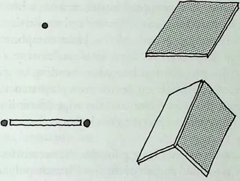
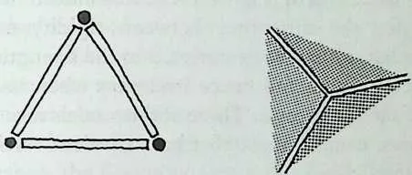
117 Figure 11.18 The dual perception of basic geometry (from top to bottom and left to right): One point, two points define a line, and three points define a plane; one plane, two intersecting planes define a line, and three intersecting planes define a point. A set of three coordinates gives the free choice of defining either the position of a point or the position of a plane, by defining the normal to the plane through the origin of the coordinate system. (Courtesy of Ola Wedebrunn.)
118 be defined, like the point, by three coordinates) and then define a one-dimensional line as an intersecting line between any two of them (which are not parallel) and a one-dimensional point as the intersection between any three planes (which do not have a common line).
119 For lattice structures the point (node) is the basic element (Figure 11.18, left), and two linked points define a line (bar) whereas three points define a plane, which is a nonactive open mesh. For plate structures the plane (plate) is the basic element (Figure 11.18, right), two linked planes define a line (shear line), and three planes define a vertex, which, if regarded as a node, is nonactive because any trivalent node may be removed from a structure without changing the redundancy of the structure.
120 A given set of geometrical and topological data can be interpreted in these two different ways, often resulting in very different looking configurations but uniquely tied together by geometrical and structural duality. It appears that all computer software with three-dimensional applications is based on the first interpretation and is therefore not suitable for handling geometrical and structural duality.
121 Modeling Polyhedral Structures
122 Physical models seem to be without peer in the study of faceted structures. Pin-jointed bars as
connectors between nodes will indicate not only the
architectural appearance of a proposed lattice structure but will often also reveal the structural
characteristics of rigidity and sensitivity. Note that the pure lattice structure only uses two of the
basic components, the vertex (node) and the edge (bar), not the facet. In a similar way a
rigid-in-plane material such as cardboard, which is hinged by bending or gluing along the
edges, will be relevant as a simple model for pure plate structures. This type uses two
components, the facet (plate) and the edge (shear line), but not the vertex, and as
it is important to prevent nodal, that is, lattice action, the vertices should be cut
away.
123 A very good exercise to get a feeling for the characteristics of lattice-and plate-based rigidity is to build models of the five Platonic polyhedra in the two versions and then try to flex them (Figure 11.9). It is indeed important to get a fingertip feeling for the difference between rigidity-movability and strength-failure. The latter quality is connected to the strength and elasticity of the material and connectors and hence irrelevant when investigating the kinematic qualities of such structures. Three of the models turn out to be rigid as pure plate structures, namely, those that have trivalent vertices: the tetrahedron, hexahedron, and dodecahedron; and three are rigid as pure lattice structures, namely, those with trivalent facets: the tetrahedron, octahedron, and icosahedron. It is remarkable that the tetrahedron, with trivalent vertices as well as trivalent facets, is rigid as a pure plate as well as a pure lattice structure. This polyhedron is, in fact, so simple that acting and reacting forces directed along the edges are balancing each other directly and no internal force distribution in the structure is needed.
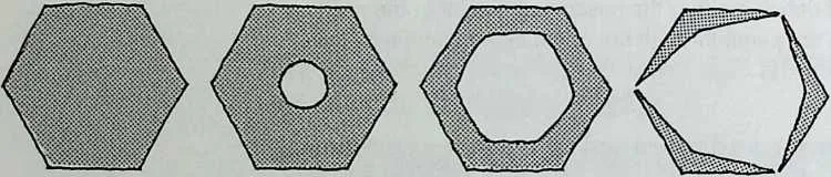
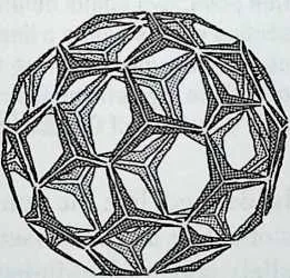
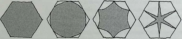
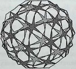
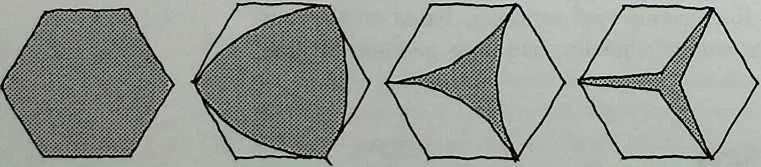
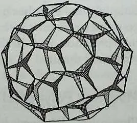
125 Figure 11.19 Methods of opening up plates without compromising the rigidity. (Courtesy of Ola Wedebrunn.)
126 Another interesting quality of these rigid structural archetypes is that they are neutral (i.e., statically and geometrically determinate or having zero redundancy), that is, on the edge of rigidity. This may easily be checked by removing one connector: a bar or a shear line.
127 The unstable versions of the regular polyhedra, for example, the octahedron and icosahedron as plate structures or the cube and dodecahedron as lattice structures, can all be stabilized by adding either bars to the lattice types or shear lines to the plate types.
128 Physical models are superior to computer models for testing structural qualities, not least because they give answers to much more than what is being asked; for instance, the flexibility or structural sensitivity of any combination of particular loading cases can be determined by physical models, whereas the computer only gives an answer to already specified loading cases. Perhaps virtual-reality technology will be developed in the future that will resolve this issue. Physical models are not often appropriate in the preliminary stages of the creative design process as it is time consuming to build good models. In the process of investigating different geometries, interactive computer modeling is obviously superior to physical models, whereas the latter are superior in investigating structural behavior.
129 Most of the computer graphics software works with wire frame models that are geometrically similar to lattice structures. These programs are often interactive and the geometry can be easily manipulated. Advanced structural analysis and computer design programs have also implemented interactive and user-friendly shaping features.
130 Computer modeling is a good deal more complicated for plate structures, but some of the advanced graphics software packages can facilitate the cutting of solids, which can be utilized for shaping plate structures, but the present software is still not efficient enough for this purpose. An adequate program should work like its lattice counterpart, with the difference that the coordinates, instead of defining nodes, should be regarded as the geometrical information for defining planes,16 and the information for linking the plates should be fisted in the correct order as if walking, either way, around the perimeter of the plate. With this information the intersections between a plate and its neighbors can be calculated and the defined plate can be isolated from the rest of the infinite plane of which it is a part. Such software is unfortunately not yet commercially available.17 Plate structures are probably not developed to the same level of complexity and sophistication as lattice structures because of their more complicated and computer-dependent geometry. If plate structures are to be used to their full potential, it is absolutely necessary to add dual transformation and the previously mentioned alternative geometrical interpretation of data to existing software.
131 Opening Up a Plate
132 One of the evident advantages of plate action compared to lattice action is that, when the enclosure of a building is designed to resist external load such as wind, snow, and dead load, it usually has an excess of bearing capacity in its own plane so that its utility for plate action is often possible. As the covering material must be there anyway, why not use it to transfer forces in its own plane by plate action? A transformation of a covered lattice structure into a plate structure often makes it possible to eliminate the bars and nodes. The cladding could then be the structure itself. The only extra property that has to be introduced is shear force resistance between adjacent plates.
133 The dual quality of lattice action, which is concentrating forces in nodes and bars, and plate action, which is distributing forces over the surface, has the effect that lattice structures tend to be constructed from strong material like metal, whereas plate structures may utilize weaker material like wood panels, plywood, plastics, reinforced concrete, and even glass!
134 That plates are essentially closed elements might be seen as a problem, as buildings usually need openings like windows, doors, and so forth. However, plates may be opened, as long as the essential requirement that they remain rigid in plane and sufficiently strong and stiff to transfer the design forces is maintained. There are essentially two different ways to open up plate structures: either by making holes inside the plates or by removing vertices (Figure 11.19). In both cases the plates develop into frames with bending rigidity in the plane of the plates. The plates become geometrically open but remain structurally closed. Plates with large openings will, of course, need more or stronger material than if they were made without holes. The larger the openings, the more plate structures will approach lattice structures from the point of view of the type of material employed.
135 PLATE AND LATTICE STRUCTURES IN NATURE
136 Structure is a major issue in our earthly environment of gravity and other loadings and many living organisms have developed highly sophisticated structural systems over millions of years. Nature’s strategy for improving solutions to structural and other vital challenges, and which has proved to be very creative and efficient, is known as ‘‘survival of the fittest.’’ A major difference from man-made structures is that organisms need to grow. It is vastly more complex to maintain strength and rigidity during a growth process than to erect a safe and rigid building. Just think of the difficulties of many beetles and crabs that have to throw away their external chitin skeleton and become very vulnerable until their new armor has solidified. Other organisms, like the sea urchin, have developed more sophisticated solutions to a similar problem.
138139It appears that many structures in nature, which can be typified as plate or lattice structures, are very close to being structurally neutral. The shell (also called the test in biological terms) of the sea urchin is one instance (Figure 11.25). Many other echinodermata, the skeleton and armored skin of many vertebrates, the Venus’s-flower-basket (Figure 11.24), the spongy trabecula inside bones (Figure 11.23), different types of spider webs, microscopic plankton such as radiolaria (Figure 11.20), foraminifera (Figure 11.21), coccolithophores (Figure 11.22), and many others are further examples. One of the obvious advantages is that a structure with low redundancy requires less material, which means less dead load, and uses less energy for its construction than a structure with high redundancy. Another advantage is that a neutral or slightly redundant structure develops lower internal stresses during growth and other structural rearrangements than a highly redundant structure. Rearrangements of the structure may therefore be achieved more easily and with less adjusted growth of the total system. Of course, kinematic neutrality is also an obvious disadvantage as the structure tends to become movable if local failure occurs, but often it seems possible to use an alternative structural action if needed. To prevent collapse, the structural action often changes into one that is less stiff than the plate or lattice action, for example, bending. For this softer type of action, the structure is redundant—this is an expansion of our normal conception of the word redundancy in the sense that a failure of the more rigid structure must occur to activate the alternative softer structural type of action. This system can be exemplified by a house in which the main structure has been badly damaged, for example, by an explosion, but has not collapsed because the forces have found alternative rearrangements, (e.g., bending).
140The sea urchin may transfer bending moments over the shear lines during the ‘‘repair period’’ of a plate. The trabecula inside our bones and the Venus’s-flower-basket do not have hinged nodes and must therefore also carry loads by the transfer of bending moments between bars if necessary. It is significant that these auxiliary ways of stabilizing are secondary as they produce larger elastic deformations than the very stiff plate and lattice action.
141In order to understand the appearance of pure plate structures in nature, it should be noted that a random single-layer configuration of planes will always intersect in trivalent vertices,18 which is the required geometrical pattern for pure plate action in single-layer structures. The same geometry is seen on randomly organized close-packed organic cells or soap bubbles, either on its surface or in cross section. One might conclude that the ‘‘creator’’ has been dealt an incredibly strong hand of cards, when the lowest geometrical order of all—the random—produces the ideal configuration for pure plate action! The rest is ‘‘just’’ to create rigid-in-plane plates and shear resistant connections in order to introduce plate action to nature. The plate type of structure is very appropriate for faceted structures as the covering surface is at the same time the main structural element, while the more complicated bar-and-node action, which requires higher-strength materials, can be avoided.
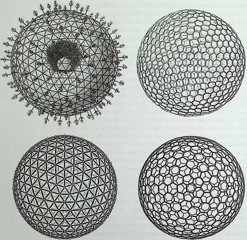
143 Figure 11.20 Radiolaria: Aulosphaera dendrophora (x80) (upper left) and Aulonia hexagonia (x30) (upper right) compared with geodesic polyhedra as a pure lattice structure (lower left) and its dual as a pure plate structure (lower right). (Source: Upper drawings: Ernst Hackel, Challenger Monograph, 1987.)
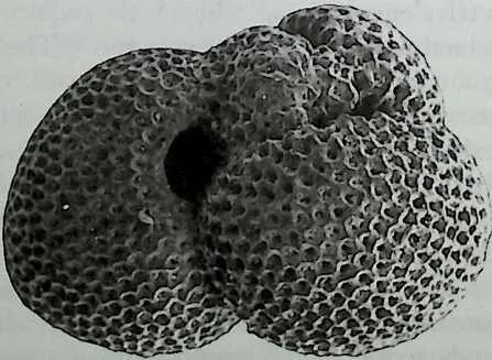
145 Figure 11.21 Foraminifera (x450), a multichambered living unit of calcium carbonate polyhedral shells. (Source: Geological Institute, University of Copenhagen.)
146 Planktonic Organisms
147 Microscopic plankton floating around in the oceans are subjected to equal loading from all directions. Plankton do not develop up-and-down orientation as many organisms subjected to gravity do. Instead, they often develop nonoriented spherical or polyhedral geometry. The biologist Ernst Hackel19 has been extremely productive in describing comprehensively the siliceous plankton called radiolaria (Figure 11.20), many of which are beautiful images of polyhedral structures. The external skeleton, even when not studied in detail, often shows either a lattice (triangular facets) or a plate (trivalent vertices) configuration—or both. Foraminifera (Figure 11.21) are calcitic organisms with similar polyhedral configurations to radiolaria. They often form clusters of polyhedral skeletons with holes producing trivalent vertices. The foraminifer starts out by forming a single chamber with one opening. When the soft organs inside grow too large to fit into the chamber, it bubbles out of the hole and creates a larger chamber, which also has one hole, and so it continues and becomes a cluster of ever-larger polyhedral cells. Coccoliths are another calcitic plankton but with the habit of collaborating to estabfish colonies forming polyhedral shapes called coccolithophores (Figure 11.22). There are several types of connections between the single coccoliths, some of them with a wedge-and-cleft connection and some where the coccoliths are just touching and held close by soft tissue, forming configurations reminiscent of plate structures.
148 Bone Structures
149 The classic example of lattice structures in nature is the trabecula inside the enlarged extremities of our tubular bones (Figure 11.23), such as are found in our thigh20 and heel bones. The calcitic trabecular structure is oriented in the optimal structural direction, which is that of the main tension and compres-
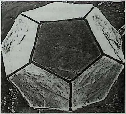
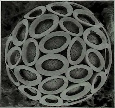
151 Figure 11.22 Coccolithophores: Braarudosphaera bigelowii (x5000), a perfect dodecahedral configuration (left). Pontosphaera discopora (x4000), forming polyhedra from packed ellipses in a trivalent vertex pattern, which indicates rigidity by plate action (right). (Source: Coccolithophores, Amos Winter and William G. Siesser, eds. Courtesy of Cambridge University Press. Photos: S. Nishida.)
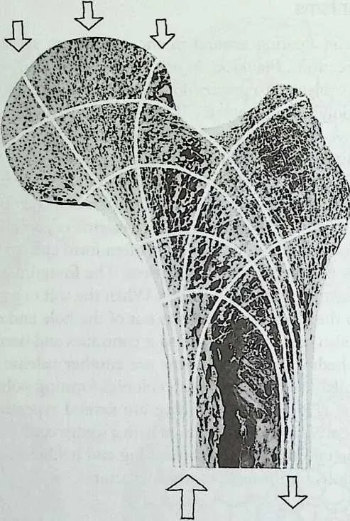
153 Figure 11.23 The spongious trabecula in the femur follow the stress trajectories for the body weight. The trajectories follow the direction of the principal stresses (shown as a pattern of white lines) in a similar solid structure at any point of the cross section. (Courtesy of Ola Wedebrunn.)
154 sion forces, the so-called stress trajectories. The trabecula are connected to the compacta, which is the compact bony layer forming the outer surface of the bone. The trajectories, forming a cubic lattice of six-valent nodes, will, together with the compacta, form an ideally shaped three-dimensional structure which, if regarded as a lattice structure, turns out to be close to neutrality, only slightly redundant. Clinical observations of the trabecular pattern of the femur (the upper extended part of the thigh bone) of astronauts and other individuals who have been subjected to unusual loading of these structural parts, show rearrangements of the pattern consistent with the quality of being almost neutral. Hence a configuration of minimum energy consumption and minimum risk of unwanted internal stresses, which might lead to failures during the rearrangement process.
155 Some of these spongious bone structures are configured as cubic cells with thin cell walls and are therefore more probably stabilized by plate action than by lattice action. It is interesting that if pure plate action is considered for plates forming a cubic matrix configuration, it will have the same kinematically neutral status as the cubic lattice.
156 Venus’s-Flower-Basket
157 The Venus’s-flower-basket Euplectella (Figure 11.24) is a deep-sea siliceous glass sponge, consisting of a cylindrical chimney-like structure topped by a
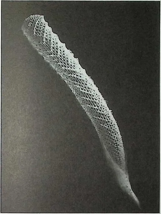
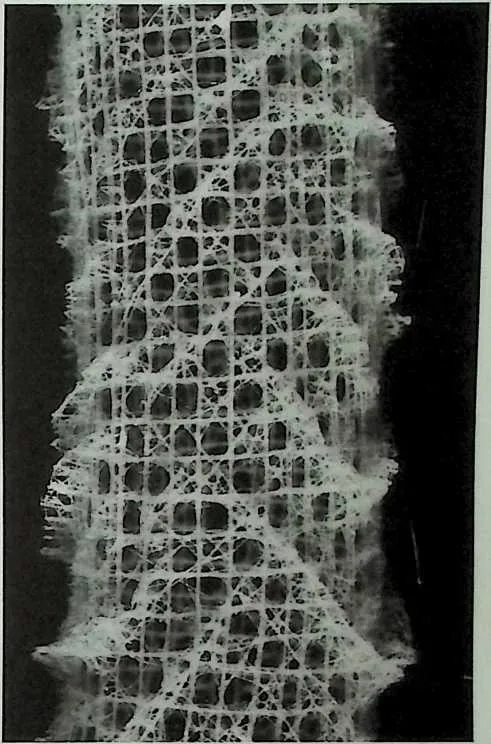
159 Figure 11.24 Venus's-flower-basket(Z. = 30 cm, D = 3 cm). Total structure and detail.
160 dome and rooted in the sea bottom with long shiny siliceous fibers. The soft organic tissue is located on the surface of the cylinder. It feeds by filtering small organisms from the sea water sucked through the meshes in the cylinder, pushing the filtered water up and out through the chimney. The meshes of the cylinder are basically squares. Every second mesh, in a chessboard pattern, is cross-braced and forms spiral lines. Half-octahedra are positioned on top of the cross-braced meshes and their upper vertices are interconnected, forming spiral ridges on the outside of the cylinder. If considered as a pure lattice structure, the configuration turns out to be neutral. The nodes are able to resist bending, which means that any local damage does not necessarily lead to total failure. The structure would also be stable if all meshes were braced, but this would interfere with the flow of nutritious water through the surface of the cylinder. Hence, the solution with the ridges appears to be very appropriate.
161 The Shell of the Sea Urchin
162 The hard shell of the so-called regular1 sea urchin (Figure 11.25) complies with all the requirements of a perfect plate polyhedron with great functionality in the design of shape, joining, and necessary geometrical openings. In addition to its ability to resist external loading, the polyhedral structure of the
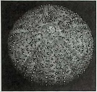
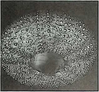
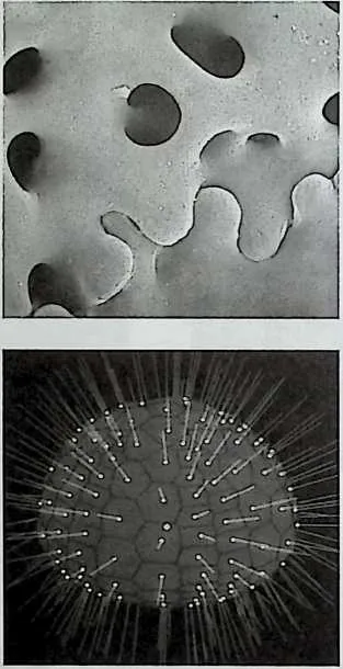
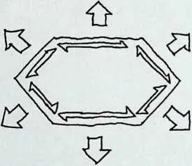
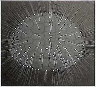
165 Figure 11.25 Regular sea urchin. Seen from above (upper left) and below (upper right). Note the trivalent vertices on the inside of the shell. Scanning electron microscopy (SEM) (x600) of the toothed link between two plates (middle left) and a drawing showing that the direction of growth and the direction of stabilizing forces are perpendicular, hence uncorrelated (middle right). Lower left and lower right are images of a computer-generated sea urchin subjected to loadings perpendicular to the surface, resembling the action and the appearance of the spines. (Courtesy of Dr. Margit Jensen, Zoological Museum, University of Copenhagen.)
167168sea urchin must, at the same time, be able to grow. This problem has been solved in a theoretically elegant way.
169The regular sea urchin surrounds its soft organs with a protective polyhedral shell of calcite. It consists of an upper almost hemispherical part and a somewhat flattened bottom part. On the outside of this hollow calcite skeleton, a great number of movable sharply pointed or club-shaped spines are arranged, providing efficient protection against attacks from enemies or rough sea. It is probably the spines that transfer the major external forces to the shell.
170The shell is basically composed of two types of plates, dividing the surface into five areas and converging at the two poles. Each area consists of two rows of plates, which may be regarded as plane plates, arranged in such a way that all vertices are trivalent. The individual plates are normally connected to between five and seven other plates.
171The larger of the two openings appears at the bottom pole where the plates meet a strong and stiff pentagonal frame, on which the highly developed chewing apparatus ‘‘Aristotle’s lantern’’ is mounted. This frame is therefore structurally closed even if it is geometrically open.
172The joins between the plates, the shear lines, are distinctly toothed (Figure 11.25). This type of connection is extremely efficient in transferring shear forces, which strongly supports the assumption of plate action. The collagen fibers almost lacing the plates help to keep the plates close together, which will enable the transfer of bending moments from plate to plate. The lacing is important for maintaining sufficient strength and stability during ‘‘repair’’ after a fracture of one or more plates. It is obvious that the plates combined with the collagen fibers enable structural actions other than plate action, for example, bending. The shell may, for example, function as a continuous shell structure. Shell action is very close to plate action because a finely faceted plate polyhedron is nothing but a slightly discontinuous shell, stabilized only by shear forces, acting across the edges.
173The sea urchin grows by increasing the number of plates and increasing the size of the single plates as a simple two-dimensional geometrical expansion. By expanding the size of the plate, the direction of growth will be perpendicular to the shear lines (Figure 11.25), hence perpendicular to the direction of the stabilizing shear forces. Growth and transfer of stabilizing forces can therefore be managed concurrently without any interference. Seen as an engineering problem, the combination of growth and maintained rigidity is solved by the sea urchin in a structurally elegant way.
174The analysis of the sea urchin as a pure plate structure leads to speculation on the structural nature of other similar configurations. Such configurations are found in the armored skin of reptiles, the shell of the tortoise, the bone structure of the skull, and many other places in nature. Scientists often find it difficult to explain the function of this significant pattern of sutures—maybe a part of the answer is given by ‘‘rigidity during growth’’!
175 EXAMPLES OF MAN-MADE STRUCTURES
177178Polyhedral lattice structures appear to be increasingly popular, especially for large spans where the high efficiency of metal lattice structures forms slender, elegant, and extremely lightweight structures. The recent demand for large sports arenas has produced a great number of sophisticated and brilliant lattice structures. There seems to be some chance that these large coverings will influence smaller-scaled buildings such as houses.
179Today’s use of plate action is mostly limited to the stabilizing of buildings against horizontal loads such as wind and earthquakes by activating floors, facades, gables, internal walls, walls around staircases, elevators, and so forth. This is a very limited use compared to the vast possibilities of complex spatial plate structures.
180As mentioned earlier, most buildings can be characterized as polyhedra or clusters of polyhedra. On the other hand, common buildings are not characterized or analyzed as polyhedra, and polyhedra are usually not on the mind of the architect during the creative process of organizing the building geometry, or on the mind of the structural engineer when making decisions about structural action and design. In fact, almost an entire generation of building designers, such as architects and engineers, are generally unaware of polyhedra and their morphological qualities. I am sure that our architectural landscape, in terms of the shape and structure of our buildings, would become increasingly interesting if architects and engineers were better trained in using the geometrical, topological, and structural archetypes for their buildings.
181A very simple example of implementing plate action in buildings is the traditional gable or pitched-roofed house. A view of such a roofscape (Figure 11.26) confirms the frequency of trivalent vertices. This is therefore a configuration where the plate action of facades, gables, roofs, attics, bays, and oriels is obviously a potential that is not realized. Of course, it is necessary that the plates be rigid in plane and that the connections be shear resistant. However, these extra requirements would often be simple additions to the existing construction tradition. An obvious advantage of utilizing the latent plate action would be to increase the structural activity of the building’s surface, hence the possibility to open up the attic space by reducing frames and trusses—partially or totally. Another advantage would be that the roofs would tend to be shaped in an appropriate way for efficient plate action or for combined lattice and plate action. Making proper use of this structural potential would lead to more diverse and interesting shapes and structures for roofs as well as for enclosures and interior partitioning.
182The Rigidity of Polyhedral Buildings
183A major structural difference between a polyhedron and a polyhedral building is that the building is supported by a connection to the ground. To form an idea of the rigidity situation of a supported polyhedron, an unsupported rigid
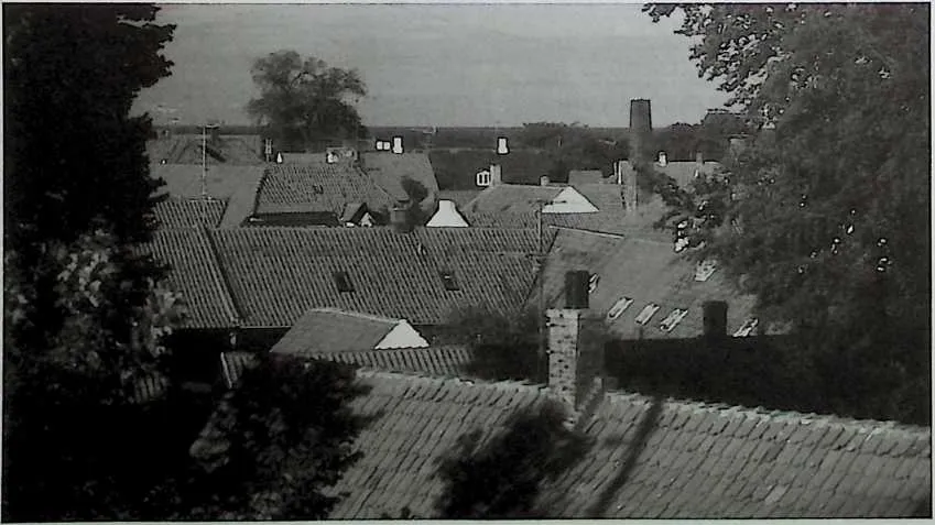
185 Figure 11.26 A common roofscape shows many trivalent vertices, indicating potential—but not utilized—plate action. (Courtesy of Ola Wedebrunn.)
186 polyhedron is first considered. Such a rigid body has six degrees of freedom22 within which to move and therefore, under the necessary general requirement for the rigidity of unsupported polyhedra, mentioned earlier, the number 6 will be replaced by the number of support conditions (SU):
188189BA + SL+ BU + SU =3x{N0 + PL)
190 Note that SU is equivalent to either a bar, a shear line, or a buffer force.
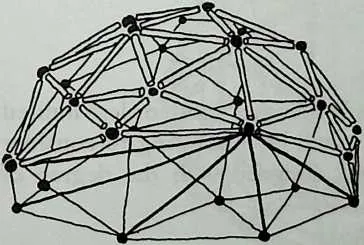
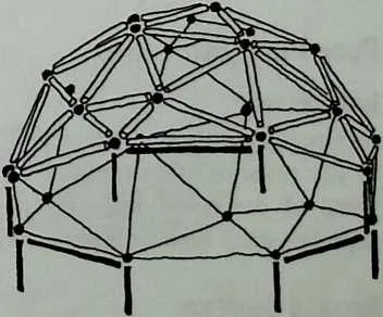
191 Imagine now any arbitrary closed and rigid simple polyhedron. Make a single cut according to the proposed foundation boundary, which does not necessarily have to be plane but in such a way that the initial polyhedral surface is still triangulated (Figure 11.27). The new polyhedron is now movable because the free edge is an n-gon (for n > 3). The number of extra bars needed to triangulate the hole will be (n -3), which are added. Now the structure has become a simple closed triangulated polyhedron and will therefore again comply with the equation
193194BA+ SL+ BU = 3x(N0+ PL)-G
195 which means that the number of support conditions only needs to be 6. As every one of the added bars is equivalent to a support, all the extra bars are equivalent to (n -3) supports. The total number of supports required to stabilize the polyhedron with the free cut edge and no extra bars is therefore 6 + (t2–3) = 72 + 3. The number of vertices on the formerly free boundary is n. If all these n points are provided with one support condition (e.g., vertical) and three of the boundary edges are provided with one support condition each (e.g., horizontal), the necessary requirement for rigidity is met. If more (e.g., horizontal) support conditions are added, the structure becomes redundant. This means that if all n free comers and all n free edges along the boundary are supported, the structure will have a redundancy of 72 -3. If this is the case, it leads to the
11.2 CONCLUSION
196that a maximum of (72 -3) bars, shear lines, buffers, or support conditions may be removed from the rest of the structure—enabling, for example, larger openings—without affecting the rigidity. Fol-
197 Figure 11.27 Stabilizing a part of a polyhedron by adding bars or supports along its periphery. Shown rotated from below. (Courtesy of Ola Wedebrunn.)
199 lowing this procedure for removing structural parts, it is very important to investigate for local movability and critical and sensitive situations. The preceding considerations are based on a pure lattice polyhedron, but the same result concerning support requirements is achieved if it is applied to any polyhedron based on plate or combined plate and lattice action.
200 Pure Lattice Structures
201 Steel lattice structures were developed by the early pioneering work of engineers during the industrial revolution, mainly in the 18th century. Progressive architects and engineers began to cultivate a significant form-and-force language for the new iron material, based on engineering qualities such as reliability, high strength, and stiffness, coincidental with the architectural qualities of airy delicacy and feathery lightness. We see the results in railway stations, exhibition halls, palm houses, libraries, and so forth.
202 Structures based on simple spherical polyhedra23 were developed by European engineers with the ‘‘father of dome structures,’’ the German, J. W. Schwedler in the lead. Later in the United States, R. Buckminster Fuller became a legend for developing—with an exceptional energy and originality—his thoughts and ideas24 on what he called the geodesic dome. The system had, in fact, already been developed and used by the German engineer Walter Baursfeld for the steel reinforcement of the Jena Planetarium in 1923. Fuller, however, became a kind of guru of the 1960s counterculture, and whole villages25 were built according to Fuller’s thinking, not only on building structures but on his total cosmology. At the other end of the spectrum, Fuller developed, in collaboration with other skilled engineers and architects, larger and fighter dome structures than had ever been erected before.
203 Polyhedral lattice buildings range from the small ‘‘homemade’’ one-family dwelling to high-tech retractable roofs for large arenas but seem to attract interest, regardless of the scale of the building. They belong to a field where engineers, because of the comprehensive structural content, must put at least as much energy into the creative process of organizing and shaping the building as the architect.
204 The lattice structure is today so commonly used, so well known, and so well documented that it will not be further dealt with here.
205 Pure Plate Structures
206 Introduction
207 As already mentioned, plate action in today’s buildings is more or less limited to the resisting of horizontal forces, but it would be interesting to consider some of the possibilities for plate structures designed with the degree of sophistication typical of lattice structures.
208 Regular Geodesics
209 Because pure plate domes can be created by the simple dual transformation of pure lattice domes (Figure 11.28), it seems obvious to consider the possibili-
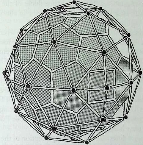
211 Figure 11.28 Dual configurations are sometimes very easy to match as in this geodesic polyhedral structure with the reference point in the center. (All art on this page courtesy of Ola Wedebrunn.)
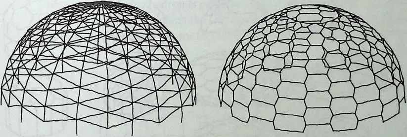
213 Figure 11.29 The dual (right) of the Schwedlertype of dome (left) is very reminiscent of the sea urchin type of faceting.
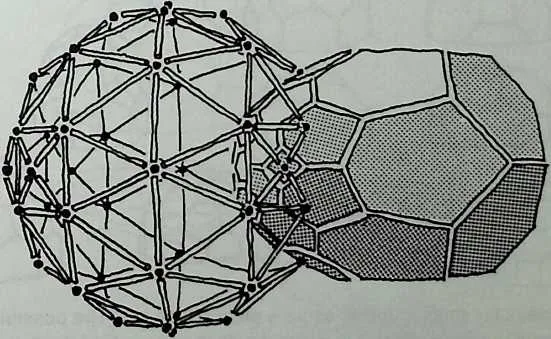
215 Figure 11.30 Dual configurations for a geodesic polyhedron. The reference point is located at one of the focal points of the ellipsoidal plate structure.
216 ties for these configurations. The pure lattice dome of the Schwedler type (Figure 11.29) will, after a dual transformation, give an almost perfect model of the shell of a regular sea urchin.
217 The duality implies that for any arbitrary pure lattice structure a dual plate structure can be found. In fact, countless numbers can be found as each position of the chosen origin produces a geometrically different plate structure (Figure 11.30). Whether the result of such a transformation creates a realistic and constructable form can often only be evaluated after the transformation.
218 A geodesic dome, according to Fuller, is produced by further triangulation (breakdown) of the triangulated regular polyhedra (the tetrahedron, octahedron, and icosahedron). Dual transformation of this kind of Fuller dome produces structural configurations for a family of interesting geodesic plate domes. As the typical nonsignificant node26 in a geodesic Fuller dome is six-valent, the dual plate becomes hexagonal.
219 There is a major difference in the visual perception of the lattice and plate dome pattern. Even with small frequencies of breakdown, the lattice dome gives a diffuse and spherical appearance, whereas the dual plate pattern appears as a more obviously faceted form. This is especially pronounced in the
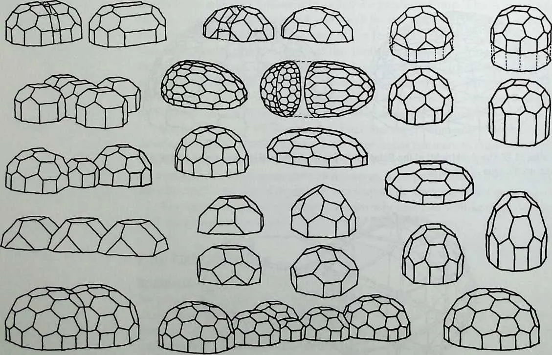
222223Figure 11.31 Ideas for smaller domes as pure plate structures. The possibility for requiring vertical plates along the perimeter in contact with the ground is latent, and the very simple geometry involved in adding units makes the plate dome in many ways superior to lattice domes. (Courtesy of Ola Wedebrunn.)
224 lower breakdowns for tetrahedron-and cube-based geodesics. In addition, these strong, almost sculptural plate forms carry a number of possibilities for direct combination with other units or as the basis for further shaping (Figure 11.31). One shaping possibility is zooming, obtained by stretching a sequence of plates with parallel intersection lines. Another possibility is stretching of the dome by applying factors to one or more of the axes, which changes, for example, a spherical shape into an ellipsoidal shape.
225 A third method for elongation of the shape I have called dual manipulation: Like stretching, this changes the inscribed sphere into an ellipsoid, but whereas stretching maintains the origin at the geometrical center, in dual manipulation the origin is situated at one of the focal points of the inscribed ellipsoid. This transformation changes the size of the plates in an interesting way, in fact so suggestive that the correct construction of a perspective view can be obtained using the following sequence (Figure 11.32):
226 ° Consider the origin in the center of the plate polyhedron.
227 ° Execute a polar reciprocation. This produces a lattice polyhedron.
228 ° Move the origin.
230231° Execute a polar reciprocation again. This produces a plate polyhedron that is different from the initial one.
232° If the new plate polyhedron is projected onto a plane that is perpendicular to the direction in which the origin was moved, this projection shows a perspective image of the initial polyhedron, as will be explained later.
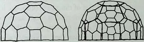
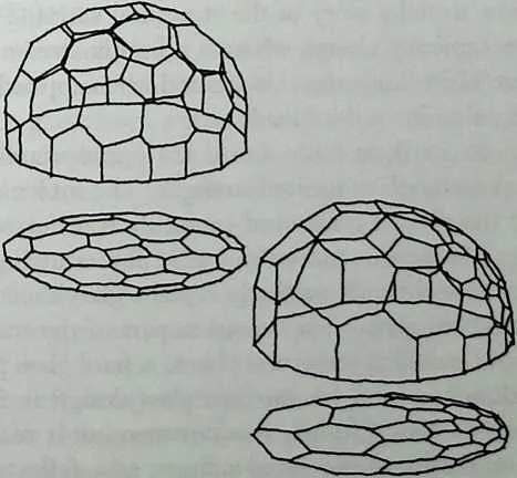
235 Figure 11.32 A dual manipulation creates not only a family of interesting geometric configurations but also a perfect perspective image of the original: The upper right appears to be a perspective view of the upper left The same configurations are shown lower left and lower right and both are viewed from above from the left (Courtesy of Ola Wedebrunn.)
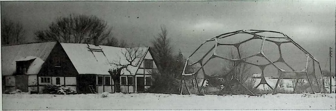
238239Figure 11.33 Next to the traditional Danish farmhouse is a pure plate dome with extremely open plates constructed as wooden frames with plywood knees. The open framed plates are bolted together. (The structure was designed by the author in collaboration with the architect Torkild Ebert in 1981.)
240 Observe now that the size of the plates has changed in such a way that those closer to the origin become smaller and plates farther from the origin become larger. The plates are circumscribing an ellipsoid as mentioned, but because of the different shapes of the plates it gives an illusion of an egg shape. Figure 11.32 shows that if the dual-manipulated polyhedron is projected onto a plane perpendicular to the direction in which the origin was moved, it creates a perfect perspective view of the original polyhedron, where the location of the eye is dual (reciprocal) to the point where the origin was moved. If the origin is moved a little compared to the size of the polyhedron, the location of the eye is far away, hence the perspective distortion is small, and vice versa.
241 Figure 11.33 shows a polyhedral plate dome of the cube family with a diameter of 12 m. The plates are open rigid wooden frames that are bolted together. Instead of all frame members or holes in the plates being of equal size, they could be adjusted to reflect the magnitude of the internal stresses. This method could be chosen to save material or to open up the roof for daylight, and not least to tell a story of the structural action: A heavily stressed plate would be completely closed, whereas a lightly stressed plate would be wide open. Figure 11.34 illustrates this method when applied to a dome of the cube family with a dominant dead load.
242 Plate structures, in their basic form, are appropriately made of two- dimensional sheet materials of limited strength. The internal stresses are distributed all over the plate surfaces and smoothly transferred along the connections, hence avoiding the concentration of forces at lines and points. A material that would fit this role perfectly is plane glass sheets. Because of the particular properties of glass—if it is used as part of the main structure of a building, it should be used as structural plates. A pure glass plate dome is one answer to the ultimate vision for modern glass design in buildings. Like a ‘‘reversed’’ Emperor’s New Clothes, it is not seen but it really is there—it is only perceived by means of the surroundings, as a reflector of the clouds, skies, neighboring buildings, and so forth.
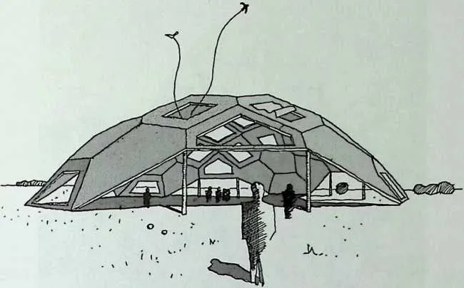
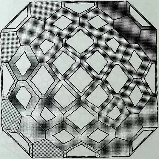
244 Figure 11.34 A shallow plate-faceted shell where the openings in the plates are adjusted to the magnitude of the internal forces for self-weight. Perspective view and plan. (Courtesy of Ola Wedebrunn.)
245 Other Polyhedral Shapes
246 A 3-m-high parabolic sculpture, called Pentagonia (Figure 11.35), was built as a pure plate structure, not from glass but from glazed ceramic tiles, which are basically similar to glass from a structural point of view. Its name is derived from the fact that both the top tile and the ground plan are regular pentagons. The 10–15-mm thickness of the tiles is greater than is needed from a structural point of view, but it is necessary in order to prevent warping of the tiles during their firing in the kiln. Clay slabs of the required thickness were cut directly from the ‘‘fold-out’’ net generated on the computer by CADual and, after firing and glazing, a sand/cement mortar was used to link the ceramic tile plates. The actual dead load is close to the ideal load for the parabolic shape. This means that the efficiency of the structural shape will be high for the dead load, and as it is the dominant load, the structure and its shape fit perfectly together. In other words, the magnitude of the shear forces to be transferred at the shear fines is minimized.
247 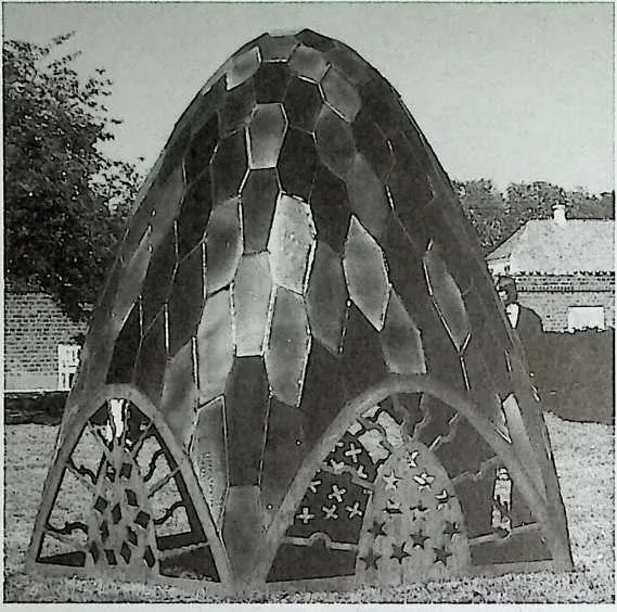
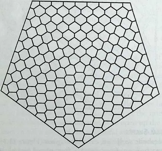 Figure 11.35 The domeshaped ceramic sculpture, called Pentagonia, circumscribes
a paraboloid of revolution, which is a structurally very efficient shape for the dominant
selfweight. It forms a 2.5-m-high ceramic pure plate dome. To ensure the transfer of shear
forces, the plates are linked with ordinary mortar. The horizontal projection shows
a very regular pattern consisting of one pentagon and just two types of hexagons.
(Ceramic artists Esben Madsen and Gudrun Rud-jord designed and produced the
sculpture in collaboration with the author. It is on display at the Silkeborg Museum in
Denmark.)
Figure 11.35 The domeshaped ceramic sculpture, called Pentagonia, circumscribes
a paraboloid of revolution, which is a structurally very efficient shape for the dominant
selfweight. It forms a 2.5-m-high ceramic pure plate dome. To ensure the transfer of shear
forces, the plates are linked with ordinary mortar. The horizontal projection shows
a very regular pattern consisting of one pentagon and just two types of hexagons.
(Ceramic artists Esben Madsen and Gudrun Rud-jord designed and produced the
sculpture in collaboration with the author. It is on display at the Silkeborg Museum in
Denmark.)
248 Polyhedral Clusters
249 Introducing plate action into traditional cubic building design should be very easy, not only with respect to the roofing, as mentioned earlier, but also for the traditional concrete element building technique. Increasing the strength of the connections between the traditional precast elements might easily enable extensive plate action and increase the architectural and functional possibilities of this building type. Figure 11.36 shows a typical example for a two-level building opened up at the lower level and carrying the loads by activating all horizontal and vertical plates and shear lines. In the same way, it is possible in
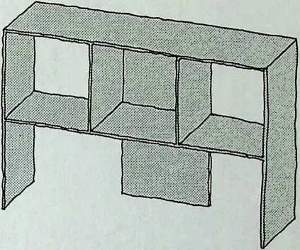
251 Figure 11.36 A simple two-story building structure based on cubic geometry and extensive use of plate action in order to open up the lower level. The building is stabilized for horizontal and vertical loadings by the transfer of shear forces between plates—and not by bending. (Courtesy of Ola Wedebrunn.)
252 a multilevel building to have alternate floors free of internal vertical structural walls. This indicates that it is possible to increase the structural efficiency and architectural possibilities by adding plate action to the conventional precast concrete building system. This is quite similar to the previous considerations for roofs.
253 Other types of polyhedral clusters are those proposed by J. F. Gabriel.27 These structures are combinations of different simple polyhedra and may be regarded as structures composed of either rigid cells, pure plates, or a combination of plates and lattices.
254 Combined Lattice and Plate Structures
255 The pure structures, plate and lattice, have their respective significant qualities, advantageous or disadvantageous, which have been outlined in the previous sections of this chapter. They form opposite poles of the structural world. They may be regarded as geometrical and structural extremes, hence the majority of their possibilities probably fie in between. The statics for the combined plate and lattice action has already been described, and the most interesting architectural potential probably lies in the area of expressing all the basic structural actions such as tension, compression, and shear.
256 An examination project investigated by engineering students considered a palm house (Figure 11.37), which is a combination of a coarse-meshed steel lattice and a fine-meshed glass plate structure. Both the steel and the glass structure adhere to the same theoretical paraboloid of revolution with the glass plates as tangential planes, whereas the steel nodes touch the same surface at the connection points with the glass plates. The rather complicated geometry, where the horizontal projection of the configuration patterns shows regular triangles (lattice structure), regularly arranged with the regular hexagons (plate structure), is easily generated by dual transformations using CADual.
257 A common problem when combining faceted spherical forms is the diffi-
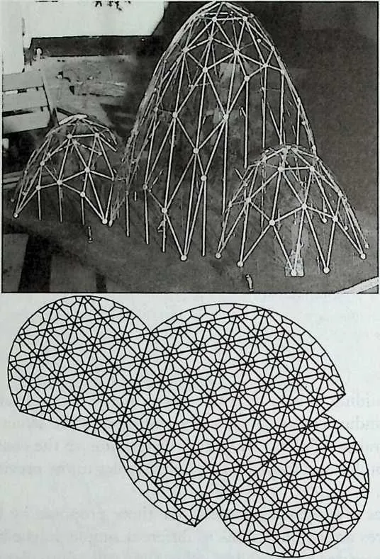
259 Figure 11.37 Palm house project. Physical model and horizontal projection of the steel and glass structure. (The illustration is of a model that was produced as part of a B.S. examination project by P. Ohannessian and N. Grunnet The project, entitled Design of a Glass Plate Dome,\Nas submitted to the Danish Technical University in 1991.)
260 culty of matching boundaries geometrically but, as the projection of the structural configuration onto the horizontal ground plane has such a strict regularity, the combination of equal types of paraboloids fits perfectly together, as shown in Figure 11.37. Because the fragile glass is part of the structure, it is important that the shape be ideal for the dead load in order to reduce the internal stresses as much as possible. The glass is self-supporting for all loading cases, but, in the case of local fracture, the redundant steel structure will prevent collapse and ensure stability until the broken glass plate is replaced.
261 Another way of combining lattice and plate action is, as with the non- trivalent simple polyhedra, to achieve strength and rigidity by transferring buffer forces along their common edges. This is exemplified (Figure 11.38) by another student project. The general shape of the highly efficient parabolic structure is the same, but all the facets are now quadrilateral and project into perfect squares on the ground plane. This time the glass is almost unaffected by dead load but plays a structural role for wind loads—similar to that of many
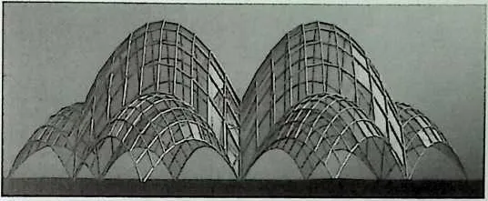
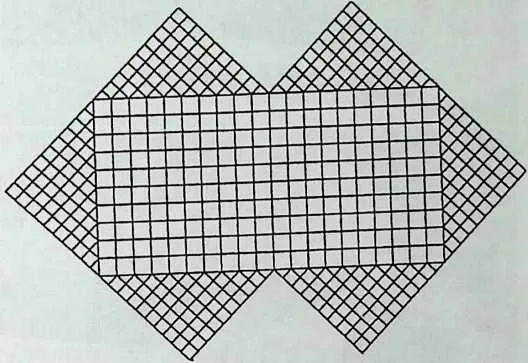
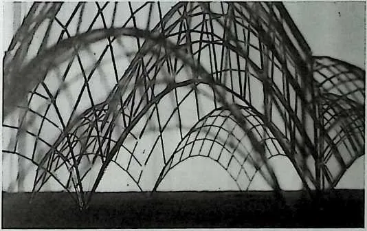
263 Figure 11.38 Project for a fruit market covering. Elevation, horizontal projection, and internal view. (The illustration is of a model that was produced as part of an M.S. examination project by P. Ohan-nessian and N. Grunnet The project, entitled Interaction Between Plate and Lattice Structure, was submitted to the Danish Technical University in 1993.)
264 old palm houses. Both projects prove that the structural performance of glass makes it very suitable for quite large structures and that the problem of brittleness could be dealt with by ensuring sufficient redundancy. The general shape and the faceting are created in a very simple way by dual transformations. At the same time, the surface turns out to be a translation surface.28 As one of the characteristics of these shapes is that the facets are plane parallelograms, which are very simple to produce, they belong to a family of structures appropriate for combined lattice and plate action.
265 Another example of the combined action is a quite interesting structure (Figure 11.39), where square plates are arranged in a chessboard pattern and hinged at the corners. This structure forms, of course, a highly movable mechanism. One can now crumple it into the desired spatial configuration and brace the open meshes in both directions. If the elements of this double brace do not intersect, then they form edges on a tetrahedron together with the
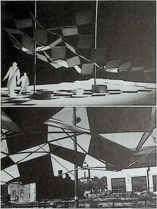
267 Figure 11.39 A chessboard pattern plate system, folded in space and braced over both the diagonals of all open meshes, becomes a rigid structure, combining plate and lattice action. The shape is defined by the actual lengths of the bracing bars. (This architectural students' project was developed by S. Krohn-Hansen and M. S. Skadborg of the Royal Danish Academy of Fine Arts.)
268 plate edges. In this case the bracing will not only stabilize the shape, but it will also enable the boundary to be free from stiffening elements, hence producing a slender and beam-free edge. If the configuration is too small or too narrow, it cannot become rigid, but above a certain size it becomes rigid and then more and more redundant as the size increases. To check this, the simplest method is to use the rigidity equations for pure lattice structures and regard the plates as braced lattice squares.
11.3 CONCLUSION
270It seems quite surprising that these simple relationships between lattice and plate (and combined) structures have been—even though Mobius came very close—so recently described. They finally have brought a perfect polyhedral order to the concept of basic structural action. On the other hand, it is strikingly difficult to change the firm opinion of many professionals that the lattice is the one and only basic static principle and the triangulated polyhedra are the only inherently rigid configurations.
271 This chapter introduces the concept that plate and lattice action are equivalent and dual in our ‘‘normal’’ three-dimensional space. This is important, as the static and geometrical rules for pure plate structures or combined lattice and plate structures produce a new and different syntax and vocabulary for shaping spatial structures—a structural morphology based on simple algebra and equally simple considerations. This basic concept for what can be called the foundation of a form-and-force language has an impact at several levels: from considerations of the dualistic qualities of basic structures to simple rules for configurational design and analysis of structures, including many biological structures, to operational tools for numerical statical analysis. As can be seen, the theory has not only led to the solution of a number of interesting structural morphological problems but also produced a tool for the design of efficient structures with the possibility of great visual and architectural qualities.
272 ACKNOWLEDGMENTS
273 I am greatly indebted to Dr. Emeritus Martyn Cundy and Dr. John Chilton, University of Nottingham, for their valuable comments and suggestions about this chapter, and to my colleague architect Ola Wedebrunn for his advice and graphical art work.
11.4 NOTES
- 1.
- Augustin-Louis Cauchy, ‘‘UMemoire sur les Polygones et les Polyedres,’’ Journal de PEcole Poly technique, Vol. 26, 1813.
- 2.
- August Ferdinand Mobius, Lehrbuch der Statik, Leipzig, 1837, Vol. 2, Chap. 4.
- 3.
- Ibid., Chap. 5.
- 4.
- Stephen P. Timoshenko, History of Strength of Materials, McGraw-Hill, New York, 1953, Chap. 10.
- 5.
- R. Bricard, ‘‘Memoire sur la Theorie de 1’Octaedre Articule,’’ Journal de Mathe-matiques, Vol. 3, 1897, pp. 113–148.
- 6.
- Robert Connelly, ‘‘A Flexible Sphere,’’ The Mathematical Intelligencer, Vol. 1, No. 3, 1978, pp. 130–131.
- 7.
- Jorgen Nielsen, ‘‘Some Stability Problems for Shear Wall Structures with Rectangular Plates,’’ Proceeding? of the IASS Symposium, Copenhagen, 1991, Vol. 2, Kunstakademiets Forlag Arkitektskolen, Copenhagen, pp. 125–127.
- 8.
- See the author’s publication Structural Order in Space—The Plate—Lattice Dualism, Royal Academy of Fine Arts, School of Architecture, Copenhagen, 1983. It was originally stated in a Danish research report of 1976. According to correspondence with Dr. Walter Whiteley, it was found independently by him at approximately the same time.
- 9.
- Ibid., p. 26.
- 10.
- The equation is deduced in the author’s paper ‘‘The Structural Behaviour of Arbitrarily Plane-Facetted Spatial Nets,’’ Proceedings of the IASS Symposium, Copenhagen 1991, pp. 119–123.
- 11.
- The magnitude of the moment vector is the product of the force and its distance to the origin. The direction of the moment vector is found by the right-handthumb rule: Let the fingers on the right hand bend over the origin with the fingertips in the direction of the force. Then the moment vector will have the direction of the stretched thumb (Figure 11.13, left center), i.e., the perpendicular direction to the force. This moment vector is acting on the origin.
- 12.
- H. M. Cundy and A. P. Rollet, Mathematical Models, Tarquin Publications, Norfolk, UK, 1981, p. 78.
- 13.
- M. J. Wenninger, Dual Models, Cambridge University Press, 1983, pp. 1–5.
- 14.
- The virtual work done by the force in a bar is required to be equal to the virtual work done by the shear force over the shear line.
- 15.
- ‘‘The Plate-Lattice Dualism,’’ Proceedings of the ICSB-IASS Colloquium, Beijing, 1981, Elsevier, London, pp. 321–328. The dual transformation equations for the elastic properties are also stated in this paper. This enables the statical calculations of redundant dual structures.
- 16.
- As described in the polar reciprocation method.
- 17.
- A research version called CADual has been developed by the author.
- 18.
- Peter S. Stevens writes on page 218 of his classic book Patterns in Nature, Little, Brown, 1974, how a piece of chalk develops facets forming trivalent vertices as it wears against the blackboard. In case a four-valent vertex seems to be found, it is just a question of magnification to separate it into two closely located trivalent vertices.
- 19.
- The German biologist and early Darwinist Ernst Heinrich Hackel (1834—1919) described some 3,500 diverse forms or species of radiolaria in his Challenger Monograph (1887). An abridged version of his famous Kunstformen derNatur from 1904 was published in English entitled Art Forms in Nature in 1974 by Dover, New York.
- 20.
- The structure is described in the classic work by D’Arcy Thompson, On Growth and Form, abridged edition, Cambridge University Press, 1961.
- 21.
- For a thorough description of the regular sea urchin, see R. D. Barnes, Invertebrate Zoology, W. B. Saunders, Philadelphia, 1974.
- 22.
- The three independent axes X, Y, and Z enable six independent movements: translation along the three axes and rotation around the same three axes.
- 23.
- See the historical article by Z. S. Makowski, ed., in Analysis, Design and Construction of Braced Domes, Granada, London, 1984.
- 24.
- Amy C. Edmondson gives an excellent insight into Fuller’s cosmology in A Fuller Explanation: The Synergetic Geometry ofR. Buckminster Fuller, Birkhauser, Boston, 1987.
- 25.
- See classics like Dome Cookbook by Steve Baer, Lama Foundation, New Mexico, 1968; Zome Primer by Steve Baer, Zomeworks Corporation, New Mexico, 1970; and Domebook 2 published by Pacific Domes, California, 1971.
- 26.
- A significant node is a node that is positioned at one of the vertices at the original regular polyhedron, e.g., a four-valent octahedral or a five-valent icosahedral node. The dual significant plates will therefore become 4-gons or 5-gons, respectively.
- 27.
- See Chapter 16.
- 28.
- A translation surface is made by two crossing polygonal lines sliding over each other. Such surfaces can easily be created by several CAD programs.