9 The Polyhedral World
2Pieter Huybers
9.1 INTRODUCTION
3It seems that the cube and the prism are at present the most common building shapes. As these two belong to the family of the so-called Platonic and Archimedean polyhedra, or, in other words, that of the regular and the semi-regular solids, this preference means a very limited choice out of a much greater source of available forms. Most of these solids have a form that is so perfect that they exert a great attraction to artists, scientists, and engineers. We find many examples in nature the shape of which is based on one of these forms, like some of the monocellular beings and crystals. However, they are also of great aesthetic as well as of practical importance. When we look more closely at the building structures around us, it appears that the polyhedral solids are actually used as a form-giving principle in building to a much greater extent than we would at first sight realize (Figure 9.1). The tetrahedron and the octahedron, for instance, have often been used in building for the composition of space structures, and the icosahedron usually serves as the starting point for a further subdivision of spherical surfaces. However, there are many more possibilities for the use of the other polyhedra, and of the forms that are derived from them, in building applications. It is therefore necessary to know in what form they occur and what their characteristics are.
4 Beyond the Cube: The Architecture of Space Frames and Polyhedra, edited by J. Francois Gabriel ISBN 0–471–12261–0 © 1997 John Wiley & Sons, Inc.
5 □ 243
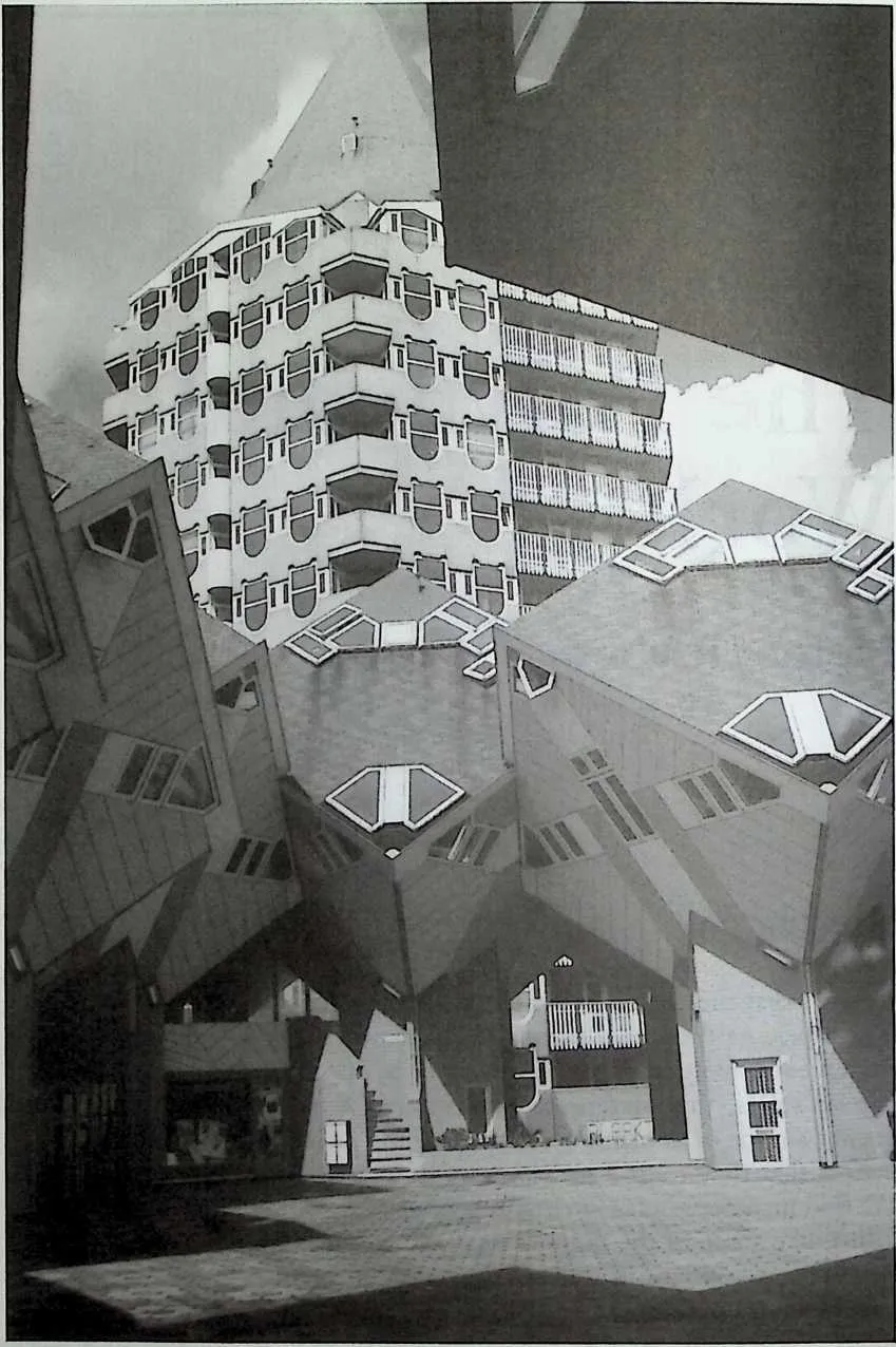
89Figure 9.1 Houses in the shape of tilted cubes by Pieter Blom in Rotterdam, the Netherlands.
9.2 WHICH POLYHEDRA DO WE KNOW?
11Definition of a Polyhedron
12 First of all we must agree on a workable definition of what we consider in this context to be a polyhedron.1 We assume that:
- 1.
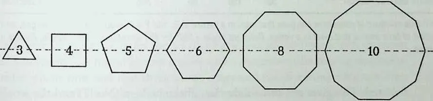
- They are covered with a closed pattern of plane, regular polygons. At this point we shall only look at the so-called Platonic solids, which are composed of identical polygons, and at the Archimedean solids, which consist of two or three different polygons. Both groups are named after the ancient scientists to which their discovery is usually ascribed.2,3 The different polygons that occur in these solids have either 3, 4, 5, 6, 8, or 10 edges.
- 2.
- All vertices of a polyhedron lie on one circumscribed sphere.
- 3.
- All the vertices are identical. This is so because around each vertex of a particular polyhedron the polygons are grouped in the same number, kind, and order of sequence.
- 4.
- The polygons meet in pairs at a common edge.
- 5.
- The dihedral angle at such an edge is always convex. This means that the dihedral angle between two adjacent polygons is less than 180°, if seen from the interior, or, in other words, the sum of the polygon face angles that meet at a vertex is always smaller than 360° (see Table 9.1).
14 The Various Kinds of Polyhedra
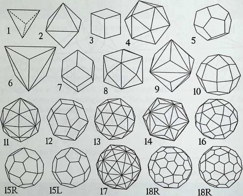
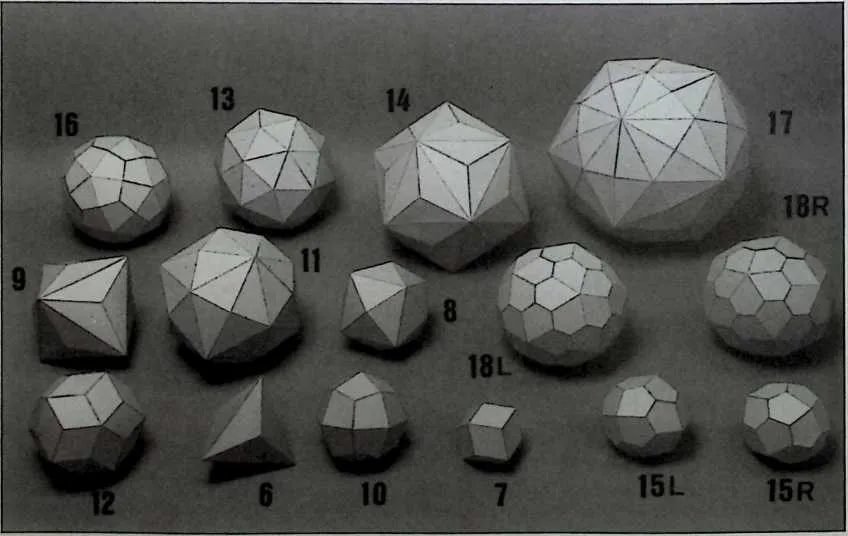
15 It is easy to understand that under these conditions the minimum total number of polygons around a vertex is three, the maximum number five, and it is also simple to prove that not more than five totally regular polyhedra can exist (Figure 9.2). These are the regular or Platonic solids and they are each composed of one kind of face. Polyhedra are called semi-regular, or Archimedean, if more than one kind of polygon is used for their construction. According to the first condition of the previous definition—namely, that the polygon has no more than 3, 4, 5, 6, 8, or 10 edges—a group of 15 principally different semi-regular polyhedra is found (see Figures 9.3 to 9.5).
16 The polyhedron numbers in Table 9.1 were introduced by the author and they are merely used here and in the following discussion in an ‘‘administrative sense.’’4 They indicate an order of sequence, based on the numbers of their faces. The Euler formula is applicable, which means that: V -E + F =2.
17 The names of the semi-regular solids show that they are generally considered to be derived from the regular solids by truncation. If this truncation is done through the vertices, so that the original faces convert to polygons with double the number of sides (i.e., triangle becomes hexagon, square becomes octagon, and pentagon becomes decagon), five new polyhedra are found: the truncated versions of the regular solids (Figure 9.4: Nos. 6, 8, 9, 13, and 14). The original face edges are divided into three parts. The truncation procedure can be carried out a little bit further so that the original edges are exactly
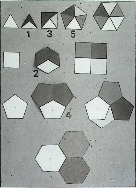
19 Figure 9.2 Derivation of the five possible Platonic polyhedra, composed of one kind of polygon, with three, four, or five sides.
20 Figure 9.3 Sketch of the 5 Platonic and the 15 Archimedean polyhedra, including two left-handed versions.
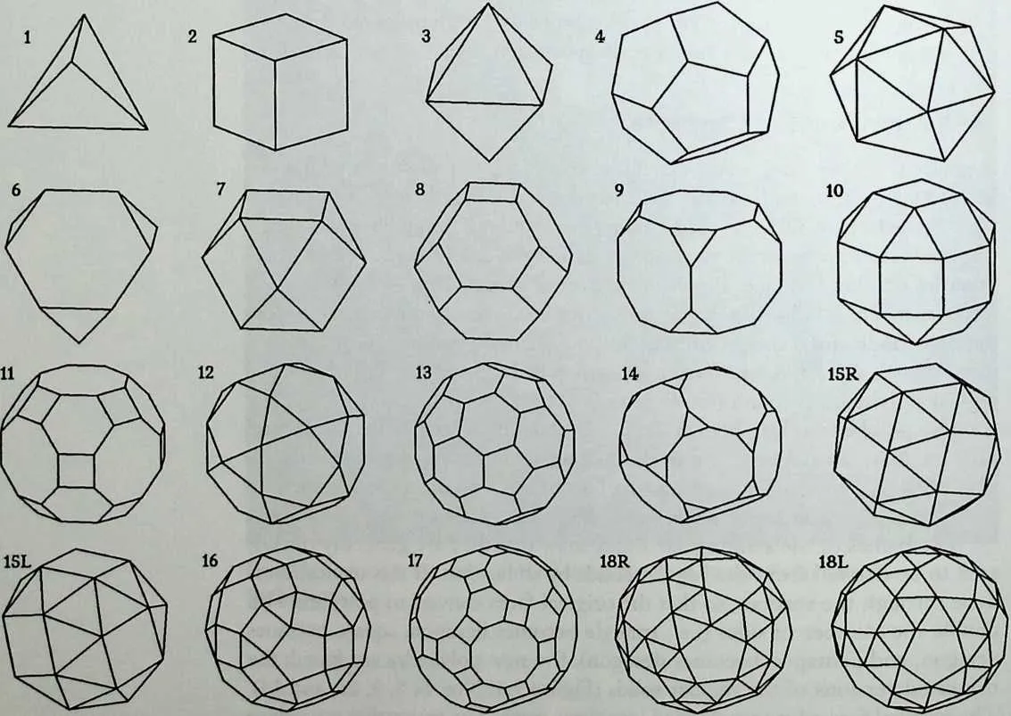
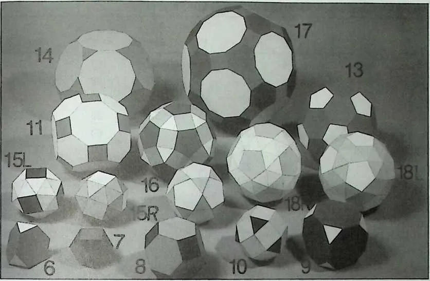
23 Figure 9.4 Photograph of the Archimedean solids.
26 b
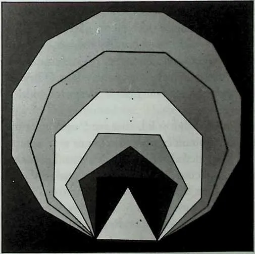
27 Figure 9.5 The different polygons in the regular and semi-regular polyhedra.
28 TABLE 9.1 Some Characteristic Aspects of the Platonic and Archimedean Polyhedra
|
32p Number |
33Code |
34Name |
35F |
36E |
37IT |
38Total Angle |
39Deficient Angle |
40Radius |
|
411 |
423–3-3 |
43Tetrahedron |
444 |
456 |
464 |
47180 |
48180 |
490.61237244 |
|
502 |
514–4-4 |
52Cube |
536 |
5412 |
558 |
56270 |
5790 |
580.86602540 |
|
593 |
603–3-3–3 |
61Octahedron |
628 |
6312 |
646 |
65240 |
66120 |
670.70710678 |
|
684 |
695–5-5 |
70Dodecahedron |
7112 |
7230 |
7320 |
74324 |
7536 |
761.40125854 |
|
775 |
783–3-3–3-3 |
79Icosahedron |
8020 |
8130 |
8212 |
83300 |
8460 |
850.95105652 |
|
866 |
873–6-6 |
88Truncated tetrahedron |
898 |
9018 |
9112 |
92300 |
9360 |
941.17260394 |
|
957 |
963–4-3–4 |
97Cuboctahedron |
9814 |
9924 |
10012 |
101300 |
10260 |
1031.00000000 |
|
1048 |
1054–6-6 |
106Truncated octahedron |
10714 |
10836 |
10924 |
110330 |
11130 |
1121.58113883 |
|
1139 |
1143–8-8 |
115Truncated cube |
11614 |
11736 |
11824 |
119330 |
12030 |
1211.77882365 |
|
12210 |
1233–4-4–4 |
124Rhombicuboctahedron |
12526 |
12648 |
12724 |
128330 |
12930 |
1301.39896633 |
|
13111 |
1324–6-8 |
133Truncated cuboctahedron |
13426 |
13572 |
13648 |
137345 |
13815 |
1392.31761091 |
|
14012 |
1413–5-3–5 |
142Icosidodecahedron |
14332 |
14460 |
14530 |
146336 |
14724 |
1481.61803399 |
|
14913 |
1505–6-6 |
151Truncated icosahedron |
15232 |
15390 |
15460 |
155348 |
15612 |
1572.47801866 |
|
15814 |
1593–10–10 |
160Truncated dodecahedron |
16132 |
16290 |
16360 |
164348 |
16512 |
1662.96944902 |
|
16715 |
1683–3-3–3-4 |
169Snub cube |
17038 |
17160 |
17224 |
173330 |
17430 |
1751.34371337 |
|
17616 |
1773–4-5–4 |
178Rhombicosidodecahedron |
17962 |
180120 |
18160 |
182348 |
18312 |
1842.23295051 |
|
18517 |
1864–6-10 |
187Truncated icosidodecahedron |
18862 |
189180 |
190120 |
191354 |
1926 |
1933.80239450 |
|
19418 |
1953–3-3–3-5 |
196Snub dodecahedron |
19792 |
198150 |
19960 |
200348 |
20112 |
2022.15583738 |
209 P = polyhedron index. Code = side numbers of respective polygons that meet in a vertex. V, E, and F = number of vertices, edges, and faces. Total angle = summation of face angles that meet in a vertex. Deficient angle = 360° (or flat situation) -Total angle. Radius = radius of circumscribed sphere.
211212bisected. This gives two new solids, the cuboctahedron (No. 7) and the icosi-dodecahedron (No. 12). These two are peculiar ones and they are called quasiregular, because they are, as their names already suggest, compounds of two pairs of regular solids. P7, the cuboctahedron, is composed of six squares (like the cube P2) and eight triangles (like the octahedron P3). Pl2, the icosido-decahedron, is composed of 20 triangles (like the icosahedron P5) and 12 pentagons (like the dodecahedron P4).
213Truncation can also take place along the edges. This generally produces square extra faces and it yields four new semi-regular solids (Nos. 10, 11, 16, and 17).
214Finally, there are two other solids that are found by truncation of the corners and a double truncation of the edges. There are, in fact, four of them, as they occur in a right-handed as well as in a left-handed (enantiomorphic) version. These are the snub cube (No. 15) and the snub dodecahedron (No. 18). These two are called after their circumscribed figures. The snub cube has six squares, each completely surrounded by triangles, whereas the snub dodecahedron has 12 pentagons in a corresponding location. They have the common characteristic that they all are based on a polygon or p-gon with a variable number/; of edges, and that these p-gons come together in a vertex with four triangles. As this variable p can have any value—with six as a maximum (one
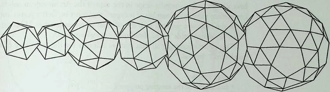
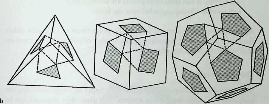
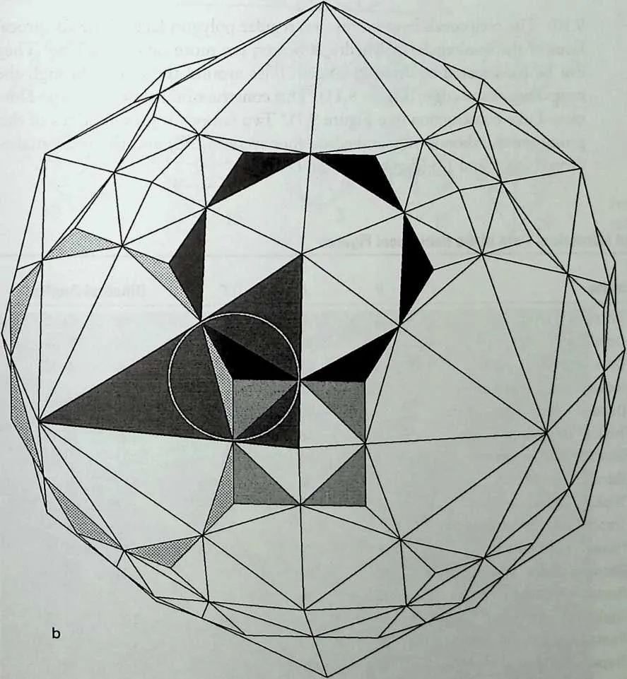
217 Figure 9.6 (a) The row of hypothetical ‘‘snub’’ solids. (b)The snub solids P18, P15, and P5.
219220hexagon and four triangles form a plane grid)—a row of figures with common characteristics is found havingp-gons with a successively increasing number of sides: six at one end and three at the other end (icosahedron). One can even go further and also take into consideration the combination of a 2-gon, which is, in fact, a line of unit edge length with four triangles. This would produce an octahedron. Thus the complete row of ‘‘snub figures’’ consists of: octahedron, icosahedron, snub cube, snub dodecahedron, plane tessellation of triangles, and hexagon.5 (See Figure 9.6a.)
221It is also possible to obtain the snub cube and the snub dodecahedron by truncation from the octahedron and from the icosahedron, respectively. These are two Platonic solids that are composed of triangles only and they differ by the fact that a variable number of triangles meet on each vertex: four in the octahedron and five in the icosahedron. There are indications that the latter derivation—from the triangular regular solids—is even more logical than the first. This would mean that the two snubs could as well be called ‘‘snub octahedron’’ and ‘‘snub icosahedron.’’ Correspondingly, the snub tetrahedron is identical to the icosahedron. (See Figure 9.6b.)
222 Vertex Situations
224225If one connects the outer ends of the edges that meet in a vertex of any of the convex polyhedra, one obtains a—sometimes irregular—polygon, which is called a vertex figure. This polygon is regular for the Platonic solids, but it can have a more or less irregular shape in the case of the Archimedean solids. It has as many sides as the number of polygons that meet in such a vertex and it forms the basis of a pyramid with the original vertex as its apex. This cap is called ‘‘Eckenpyramide’’ by M. Bruckner or vertex pyramid.6
226This pyramid contains all data that are relevant for the geometry of the polyhedron, that is:
- edge length
- face angles of the meeting polygons
- curvature of the circumscribed sphere, which is defined by the fact that the vertex as well as all its neighbors are situated on it
- all possible dihedral angles between the faces
228229A vertex pyramid is characteristic for a specific polyhedron and it can be either three, four, or five sided, depending on the number of polygons that meet on each vertex of a particular polyhedron.
230The Reciprocals
231The reciprocal or dual figure of a polyhedron is found by interconnecting the midpoints of all edges that meet in a vertex. The plane thus obtained can be expanded until it meets similar adjacent planes. The section lines between these planes bisect the original edges of the polyhedron perpendicularly and are also perpendicular to the line that connects the midedge with the center of the polyhedron.7,8 (See Figures 9.7 and 9.8.)
232The reciprocals of the semi-regular or Archimedean solids have the following characteristics (see also Table 9.2):
- All faces are identical and have as many edges as the number of the polygons, meeting on the vertices of the original polyhedron.
- The number of faces is equal to the original number of vertices.
- The number of vertices is equal to the original number of faces.
- The number of edges remains the same.
- The edges bisect the original edges perpendicularly and tangent to the midsphere (Figure 9.10).
- All dihedral angles in a reciprocal solid are equal and specific for each of them.
234235The Reciprocal Faces
236The face of a reciprocal figure can have either three, four, or five edges, depending on the number of w-gons in the original solid that occur on each vertex (Figure 9.9).
237The five regular polyhedra appear to be self-reciprocal, for example, tetrahedron-tetrahedron, octahedron-cube, and dodecahedron-icosahedron (Figure
238 deficient angle
239 Figure 9.7 faThe vertex pyramid of a polyhedron (in this case P13). 6W The Dorman-Luke construction method of the reciprocal solids.
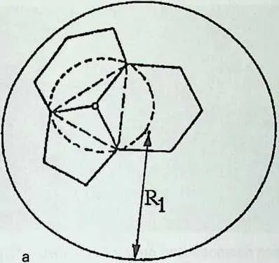
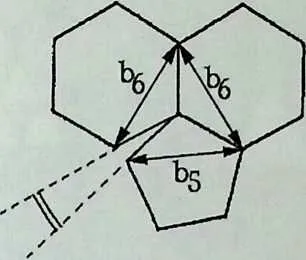
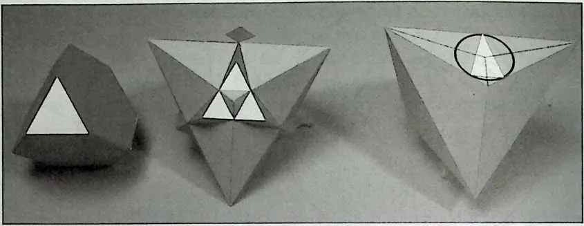
243244Figure 9.8 The Dorman-Luke construction demonstrated on the polyhedron P7.
2459.10). The reciprocals have in this case regular polygon faces. The reciprocal faces of the semi-regular polyhedra, however, are more or less scalene. They can be constructed by drawing tangent lines around the circle through the midpoints of the edges (Figure 9.11). This construction is known as the Dorman-Luke construction (see Figure 9.7).9 Two famous representatives of this group are the rhombic dodecahedron (honeycomb cell) and the triacontahe-dron (Nos. 7 and 12) (Figure 9.12zz and V).
246 TABLE 9.2. Names and Numerical Data of the Reciprocal Figures
|
250R Number |
251Name |
252V |
253E |
254F |
255Dihedral Angles |
|
2561 |
257Tetrahedron (edge = 1) |
2584 |
2596 |
2604 |
26170° 31'43.61’’ |
|
2622 |
263Octahedron (edge = /T) |
2646 |
26512 |
2668 |
267109° 28' 16.39’’ |
|
2683 |
269Cube (edge = 1/2 /T) |
2708 |
27112 |
2726 |
27390° 00' 00.00’’ |
|
2744 |
275Icosahedron (edge = t) |
27612 |
27730 |
27820 |
279138° 11'22.87’’ |
|
2805 |
281Dodecahedron (edge = 1/t) |
28220 |
28330 |
28412 |
285116° 33' 54.18’’ |
|
2866 |
287Triakis tetrahedron |
2888 |
28918 |
29012 |
291129° 31' 16.31’’ |
|
2927 |
293Rhombic dodecahedron |
29414 |
29524 |
29612 |
297120° 00' 00.00’’ |
|
2988 |
299Tetrakis hexahedron |
30014 |
30136 |
30224 |
303143° 07' 48.37’’ |
|
3049 |
305Triakis octahedron |
30614 |
30736 |
30824 |
309147° 21'00.36’’ |
|
31010 |
311Trapezoidal icositetrahedron |
31226 |
31348 |
31424 |
315138° 07' 04.65’’ |
|
31611 |
317Hexakis octahedron |
31826 |
31972 |
32048 |
321155° 04' 55.85’’ |
|
32212 |
323Rhombic triacontahedron |
32432 |
32560 |
32630 |
327144° 00' 00.00’’ |
|
32813 |
329Pentakis dodecahedron |
33032 |
33190 |
33260 |
333156° 43' 06.79’’ |
|
33414 |
335Triakis icosahedron |
33632 |
33790 |
33860 |
339160° 36' 45.19’’ |
|
34015 |
341Pentagonal icositetrahedron |
34238 |
34360 |
34424 |
345136° 18' 33.24’’ |
|
34616 |
347Trapezoidal hexecontahedron |
34862 |
349120 |
35060 |
351154° 07' 16.9’’ |
|
35217 |
353Hexakis icosahedron |
35462 |
355180 |
356120 |
357164° 53' 16.41’’ |
|
35818 |
359Pentagonal hexecontahedron |
36090 |
361150 |
36260 |
363153° 10'43.44’’ |
371372Thenames in this table give an indication of the number of faces. The suffix ‘‘-kis’’ means: number of subdivision. Furthermore, r = 11 + J 5 ):2 or the golden section. The numbers in the first column of this table refer directly to that of their related polyhedra in Table 9.1.
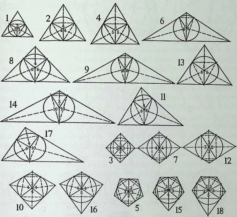
374 Figure 9.9 Sketch of the reciprocal faces.
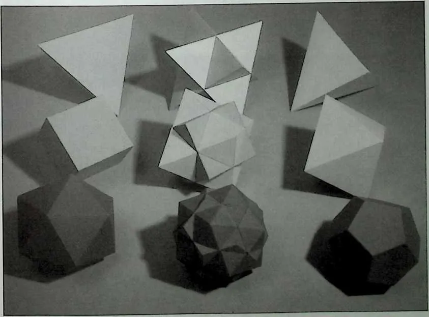
376 Figure 9.10 The mutual reciprocity of the regular polyhedra.
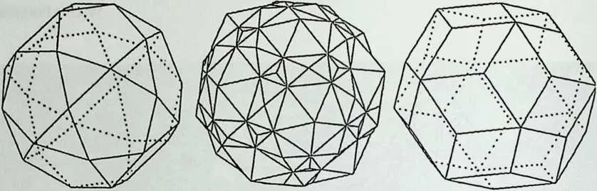
378 Figure 9.11 The derivation of the rhombic triaconta- hedron (P12).
381 Figure 9.12 (a) Sketch of the reciprocal figures. The numbers refer to those of the solids from which they are derived (see also Figure 9.3). (6/The reciprocal figures of the semi-regular solids.
382 b
383 Prisms and Antiprisms
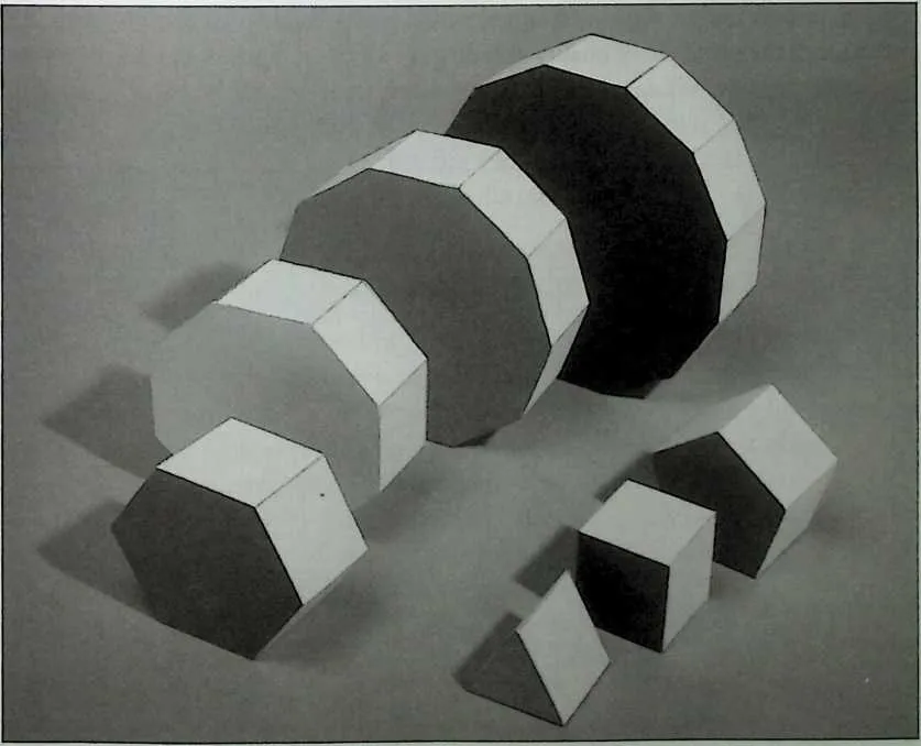
384 Prisms have two identical, parallel polygonal faces that are kept apart by a closed ring of squares, like the top and bottom of a box with square side faces. Antiprisms are similar to prisms, but they have one polygonal face rotated with respect to the other, so that the square side faces turn into triangles (Figures 9.13 and 9.14). The two polygons and the square or triangular faces of the mantle enclose a portion of space that is completely surrounded by regular polygons. In addition, they satisfy all of the previously mentioned criteria of the Archimedean polyhedra. Specimens of both groups can be called p- gonal after the number of sides p of the parallel polygons.They have vertex pyramids with a basis of the form 4–4-x for prisms (triangular) and 3–3-3-x (trapezoidal) for the antiprisms. They too have reciprocal forms; these are called polygonal (or /i-gonal, again with p for the number of sides) dipyramids and trapezohedra (Figure 9.15). They differ from the other polyhedra in one respect: The two parallel polygons can have any number of sides. Therefore, the two groups of prisms and antiprisms form endless rows.
385 In this context the name of Johannes Kepler must be mentioned.10 He lived from 1571–1630 and in his Harmonices Mundi he gave a complete survey of the 5 regular and the 13 semi-regular solids. As explained before, two members of the second group, the snub solids (Nos. 15 and 18 in Figure 9.3) have a lefthanded and a right-handed version. Kepler mentioned explicidy for the first
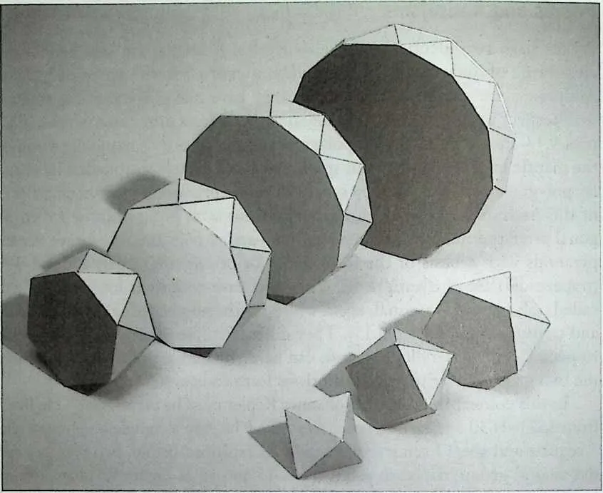
389390Figure 9.14 Regular antiprisms.
391time in history the prisms and antiprisms and showed them in sketch form. He introduced the principle of duality and he gave all these figures the Latin names by which they are still known. There are a few overlaps with the other solids: The square prism is identical to the cube and the triangular antiprism is identical to the octahedron. It is sometimes interesting to include also the 2-gonal antiprism, as it is identical to the tetrahedron (Figures 9.14 and 9.18&).
392The Stellated or Kepler-Poinsot Polyhedra
393Kepler also mentioned two stellated figures, the small and the great stellated dodecahedra (Figure 9.16). The small stellated dodecahedron (No. 3) can be constructed by placing on the faces of a dodecahedron pentagonal pyramids of such a height that they are in extension with some of the adjacent faces of the basic polyhedron. The result is that they have the appearance of 12 interpenetrating, pentagonal star polygrams, or pentagrams (Figure 9.17). The great stellated dodecahedron (No. 4) is derived similarly by the placement of triangular pyramids on an icosahedron. This also results in a compound of 12 pentagrams. Poinsot in 1809 discovered two more stellated regular polyhedra: the great dodecahedron (No. 2) and the great icosahedron (No. 1), which, respectively, can be considered as an intersection of 12 pentagons or of 20 triangles.11 The star polyhedra, in fact, do not satisfy the fifth condition of the definition that was given for polyhedra, as they are not convex at all places.
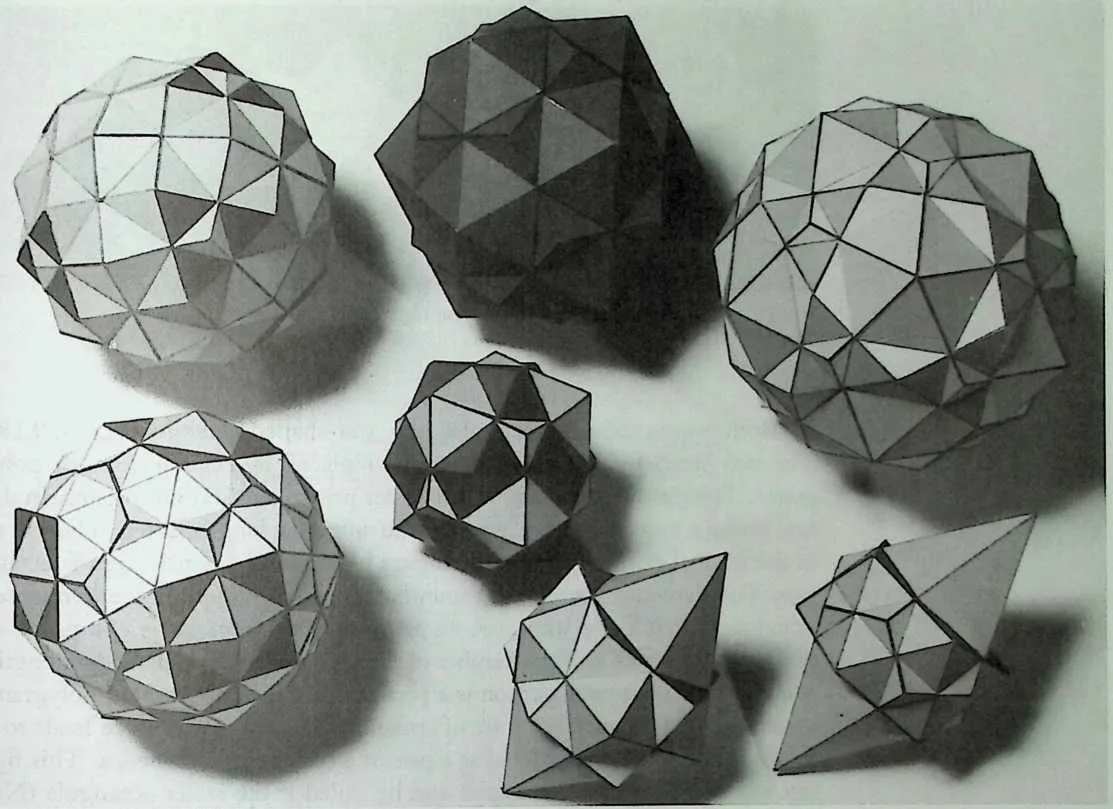
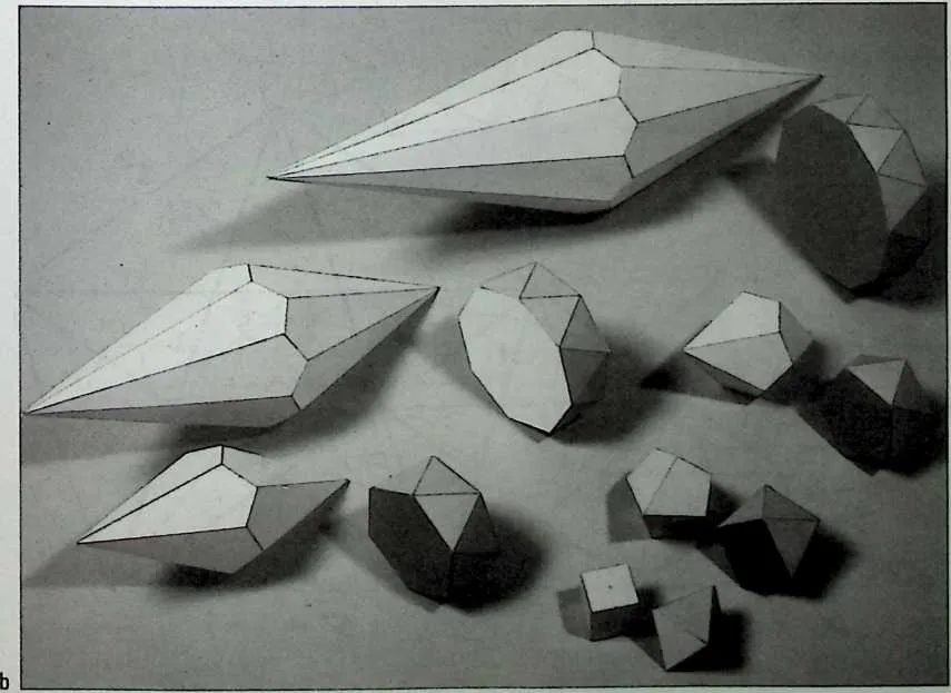
396 Figure 9.15 (a) A number of compounds of polyhedra and their reciprocal figures. 6W Antiprisms and their reciprocals.
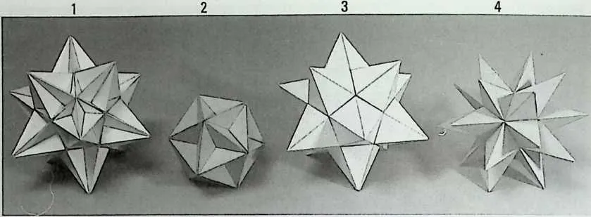
399400Figure 9.16 The four regular star polyhedra.
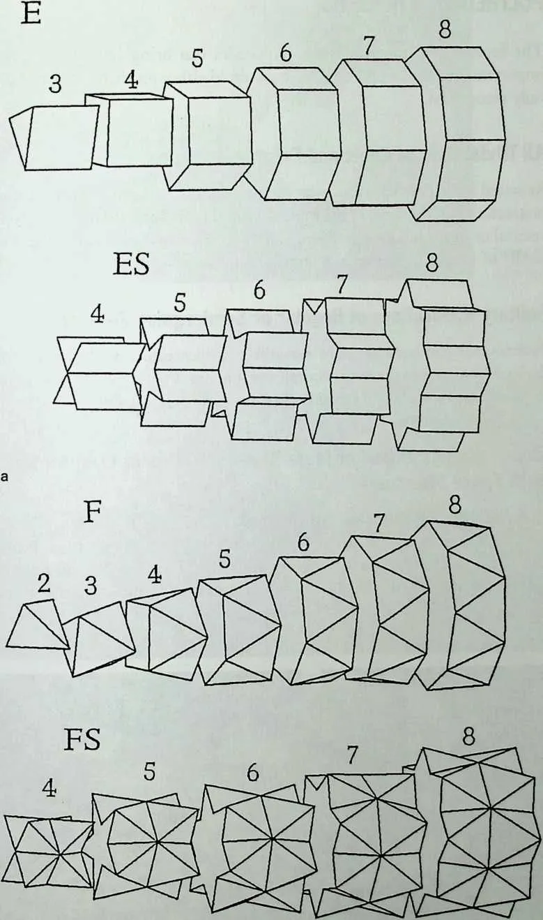
401 Both prisms and antiprisms also have star-shaped versions (Figure 9.18). The two parallel polygonal faces can be replaced by regular stars or polygrams. This produces two new families: star prisms and star antiprisms. In the first group a mutual distance, equal to the unit edge length, can be chosen, as in the normal prism. The resulting figure has a mantle, consisting of rectangles. The star antiprisms have a somewhat unexpected appearance. On closer examination the forms with even numbers of sides seem to be composed of two antiprisms with half the number of faces, but with a greater edge length. Among these the square version is a peculiar one. The four-sided polygram, or tetragram, is identical to a set of crossing lines and it therefore leads to a figure, which can be considered as a pair of intersecting tetrahedra. This figure was also discovered by Kepler and he called it the Stella octangula (No. FS-4 in Figure 9.18).
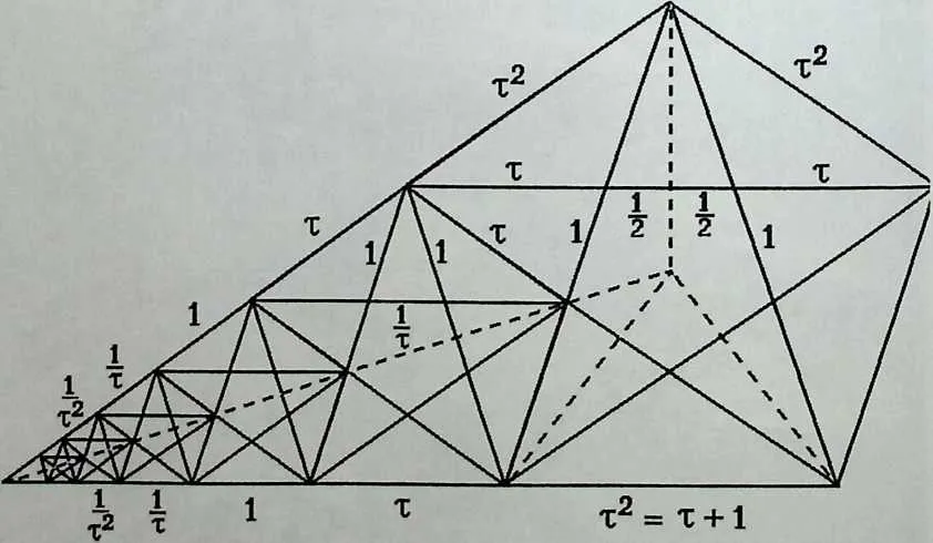
404405Figure 9.17 A row of successive pentagrams, with t = (1 + /5~):2.
408409b
410 Figure 9.18 Star prisms and antiprisms.
411 POLYHEDRA IN BUILDING
412 The form-giving possibilities that polyhedra can bring to buildings is very important, and their applications are manifold although this fact is not always fully recognized.
413 All Trivial Uses of Cubic and Prismatic Shapes
414 As stated in the introduction, most of our present-day architectural forms are prismatic (with the cube as the most common member). Prisms are used in a vertical or in a horizontal position, in pure form or in distorted versions. This family of figures is therefore of utmost importance for building.
415 Solitary Applications of Regular or Semiregulair Polyhedra
416 Architecture can become more versatile and interesting with macro forms, derived from one of the more complex polyhedra or of their reciprocal (dual) forms. Unfortunately, this has not often been done (Figures 9.19 to 9.22).
417 Close Packings of One or More Kinds of Solids in Conglomerates or in Space Structures
418 Some of the polyhedra lend themselves to being put together in tight packing formations (Figure 9.23). In this way quite complex building forms can be realized. Such packings are also suitable as the basic configuration for space frames, because of their great uniformity: identical mem-
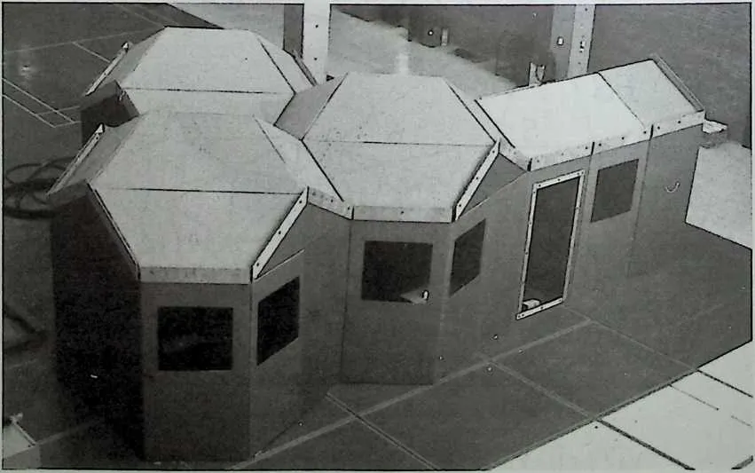
420 Figure 9.19 Full-scale cardboard house based on P8.
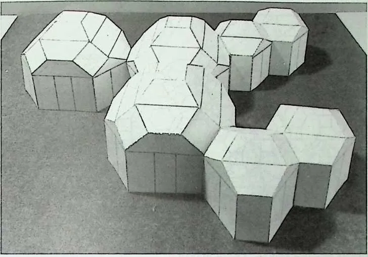
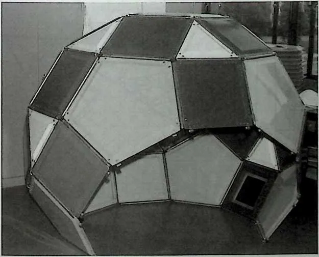
422 Figure 9.20 Scale model of a polyhedron house.
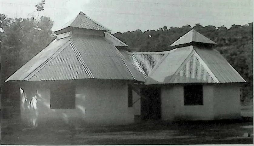
423 Figure 9.21 Office building in Bamako, Mali, based on P10.
424 Figure 9.22 P16 model, made of GRP sandwich panels.
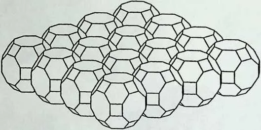
427428Figure 9.23 Packing of polyhedra (P11).
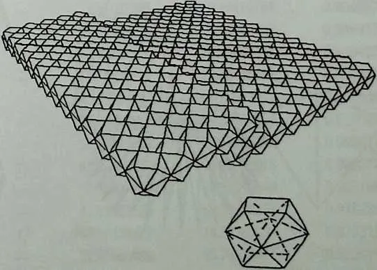
429 bers meeting at specific angles. These members usually meet at joints having a polyhedral form. The rhombianboctahedron (PIO) is well known in this respect, as it is the node of the famous MERO system. The struts meet the joint on the square faces. The joint has 18 such faces that have mutual positions and angles allowing the formation of various frame shapes (Figures 9.24 to 9.27).
430 Prismatic and Antiprismatic Forms
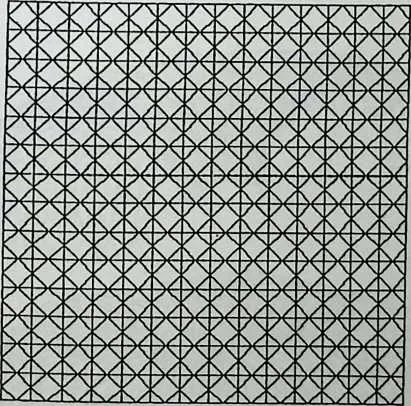
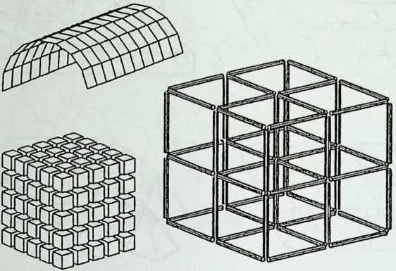
431 The simplest structural forms are the prismatic shapes. They usually fit well together and they allow the formation of many variations of close packings. Figure 9.28 shows examples of such applications: Matrices can be formed with regular or deformed prisms, parts can be linked up in rows to make cylinders, or elongated prisms can serve as the struts of space frames. If a number of antiprisms is put together according to their polygonal faces, a geometry is
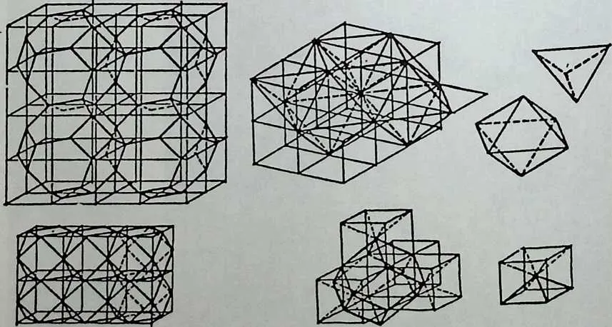
434435Figure 9.24 Possible space frame configurations.
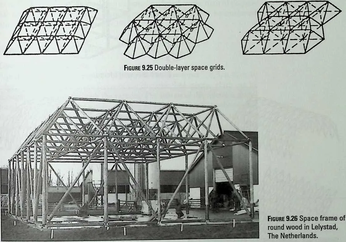
436 Figure 9.27 Triple-layer space grids, based on P7.

438 Figure 9.28 Prismatic forms.

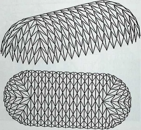
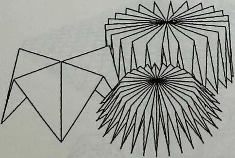
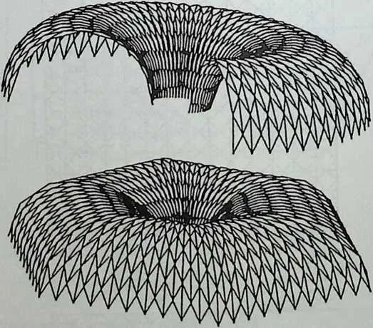
440 obtained that is often used as the basis for structural applications. The outer mantle has the appearance of a cylindrical, concertina-like folded plane. These forms can be described with the help of only a few parameters. Tonon mentions methods that modify the general shape of antiprismatically folded planes.12 This has been worked out by the author for circular transformations, so that toroidal and spherical overall forms are found on the basis of polygonal or star-formed prisms and antiprisms.13 Parts of these can be combined into larger compounds (Figure 9.29).
441 Hemispherical Structures
442 Compactness of Polyhedra
443 A polyhedron can be composed of polygons that have either 3,4, 5, 6, 8, or 10 edges. These polygons are facets of the circumscribed sphere, which can be thought of as going through the vertices. The volume of this sphere is therefore larger than that of the corresponding polyhedron. This is also the case for the area of their envelopes. The closer these two values are, the better is the approximation of the sphere that is reached by a particular polyhedron. The closeness of this approximation can be expressed in a value called the compactness of a polyhedron (Table 9.3).
444 The compactness Cp is equal to the quotient of the area of a sphere with
445 TABLE 9.3 Compactness of Polyhedra
|
4492=p |
Number of Polygon Sides
|
4502=Volume |
4512=Area |
4522=Compactness CP |
|||||
|
4543 |
4554 |
4565 |
4576 |
4588 |
45910 |
||||
|
4601 |
4614 |
462— |
463— |
464— |
465— |
466— |
4670.11785113 |
4681.73205080 |
4690.67113929 |
|
4702 |
471— |
4726 |
473— |
474— |
475— |
476— |
4771.00000000 |
4786.00000000 |
4790.80599597 |
|
4803 |
4818 |
482— |
483— |
484— |
485— |
486— |
4870.47140452 |
4883.46410161 |
4890.84558252 |
|
4904 |
491— |
492— |
49312 |
494— |
495— |
496— |
4977.66311896 |
49820.64572881 |
4990.91045318 |
|
5005 |
50120 |
502— |
503— |
504— |
505— |
506— |
5072.18169499 |
5088.66025403 |
5090.93932565 |
|
5106 |
5114 |
512— |
513— |
5144 |
515— |
516— |
5172.71057599 |
51812.12435565 |
5190.77541318 |
|
5207 |
5218 |
5226 |
523— |
524— |
525— |
526— |
5272.35702260 |
5289.46410161 |
5290.90499718 |
|
5308 |
531— |
5326 |
533— |
5348 |
535— |
536— |
53711.31370850 |
53826.78460969 |
5390.90991772 |
|
5409 |
5418 |
542— |
543— |
544— |
5456 |
546— |
54713.59966329 |
54832.43466436 |
5490.84949368 |
|
55010 |
5518 |
55218 |
553— |
554— |
555— |
556— |
5578.71404521 |
55821.46410161 |
5590.95407961 |
|
56011 |
561— |
56212 |
563— |
5648 |
5656 |
566— |
56741.79898987 |
56861.75517243 |
5690.94316565 |
|
57012 |
57120 |
572— |
57312 |
574— |
575— |
576— |
57713.83552594 |
57829.30598284 |
5790.95102430 |
|
58013 |
581— |
582— |
58312 |
58420 |
585— |
58755.28773076 |
58872.60725303 |
5890.96662189 |
|
|
59014 |
59120 |
592— |
593— |
594— |
595— |
59612 |
59785.03966456 |
598100.99076015 |
5990.92601248 |
|
60015 |
60132 |
6026 |
603— |
604— |
605— |
606— |
6077.88947740 |
60819.85640646 |
6090.96519625 |
|
61016 |
61120 |
61230 |
61312 |
614— |
615— |
616— |
61741.61532378 |
61859.30598284 |
6190.97923697 |
|
62017 |
621— |
62230 |
623— |
62420 |
625— |
62612 |
627206.80339887 |
628174.29203034 |
6290.97031268 |
|
63018 |
63180 |
632— |
63312 |
634— |
635— |
636— |
63737.61664996 |
63855.28674495 |
6390.98201136 |
647648The values of Volume, Area, and Compactness are expressed in unit edge length.
649the same volume as the polyhedron with index p, divided by the surface area of this polyhedron. This value is given by the following equation:
650 Vse-ir* Volume,2
Cp =
651 Area,
653654Pyramided or Polar Versions of Solids
655Pyramidization or ‘‘sphere point raising’’ is a technique whereby the center of a polygonal face of a polyhedron is raised until it lies on the circumscribed sphere. If these new polar points are connected to the polygon corners with inclined lines, a further subdivision is obtained that has a better approximation to the sphere. The technique is often applied in order to reduce the size of larger polygons. It can therefore be considered as the first grade of subdivision of the circumscribed sphere, which can be done with any of the known poly- hedra. It is clear that the 8-and 10-gon are not very useful in this respect, as we would get long inclined edges and narrow triangular faces. We know, however, of a number of applications where polyhedra consisting of polygons with smaller numbers of edges have been used. Many radomes have been built of hexagonal and pentagonal pyramids, usually made of GRP (glass-fiber-rein-forced polyester) (Figures 9.30, 9.31, and 9.43).14
656Polyhedral Sphere Subdivisions
657Triangular Subdivision Methods. For the further subdivision of spherical surfaces in most cases the icosahedron is used as a starting point, because it consists of
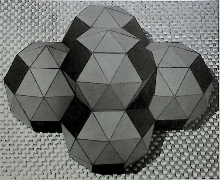
659 Figure 9.30 Scale model of pyramidized P8 compound.
660 Figure 9.31 Octagon House by K. Critchlow, based on a compound of truncated and pyramidized reciprocal solid R7. (Source: R. Sheppard et al., Paper Houses, Survival Scrapbook 4, Unicorn Bookshop, Caerffydin, USA, 1974.)
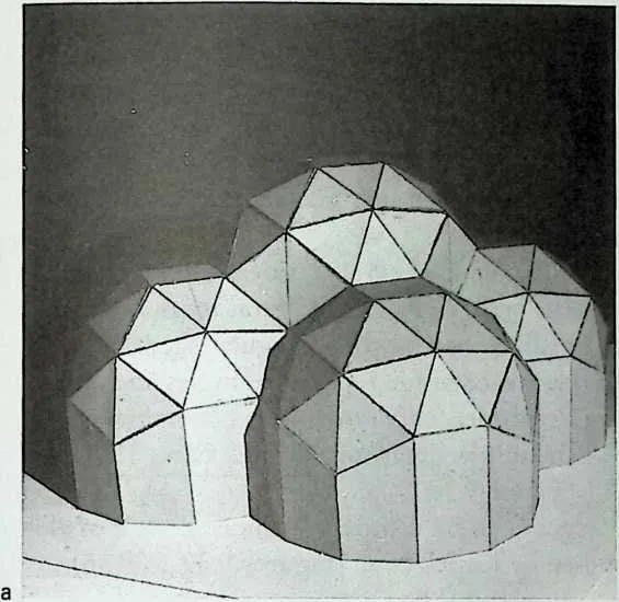
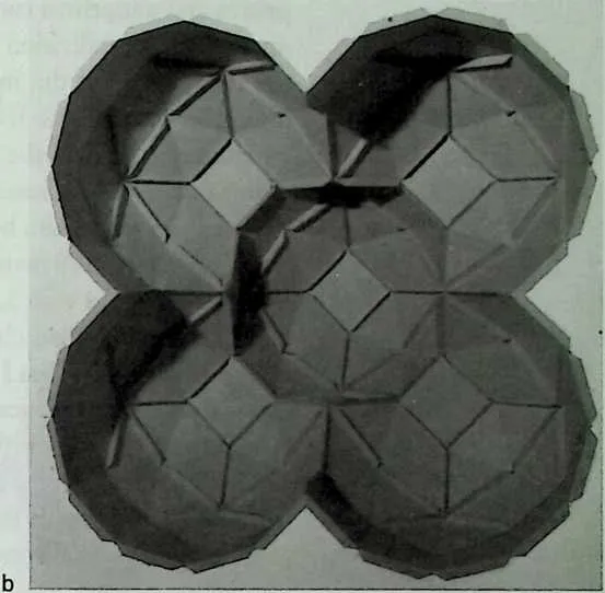
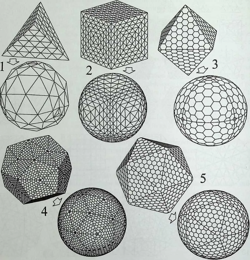
662 20 equilateral triangles that can be easily covered with a suitable pattern that is subsequently projected upon a sphere. This leads to economical kinds of subdivisions up to high frequencies and with relatively small numbers of different member lengths. There are two other triangular regular solids that can be used similarly: the tetrahedron and the octahedron.15"20
663 The original polyhedron triangle has to be subdivided up to a suitable frequency, so that elements are produced of the required maximum or minimum length. This can be done using several methods, each of which has its own advantages.
664 Generally, two main methods are considered:
- 1.
- Subdivision of the polyhedron edge in equal parts and successive interconnection of corresponding points on opposite edges of the triangular face, so that a pattern of regular small triangles is found. This pattern is then projected from the center onto the surface of the sphere.
- 2.
- Subdivision of the polyhedron edge in equal parts of the spherical angle under which this edge is seen from the center, so that, in the case of the sphere, equal chords are found. The parts into which the edge is subdivided are no longer equal and, if opposite points are interconnected, the connection lines therefore do not intersect in points but form small triangular ‘‘windows,’’ as Clinton calls them.21 The centers of these windows are successively projected onto the envelope.
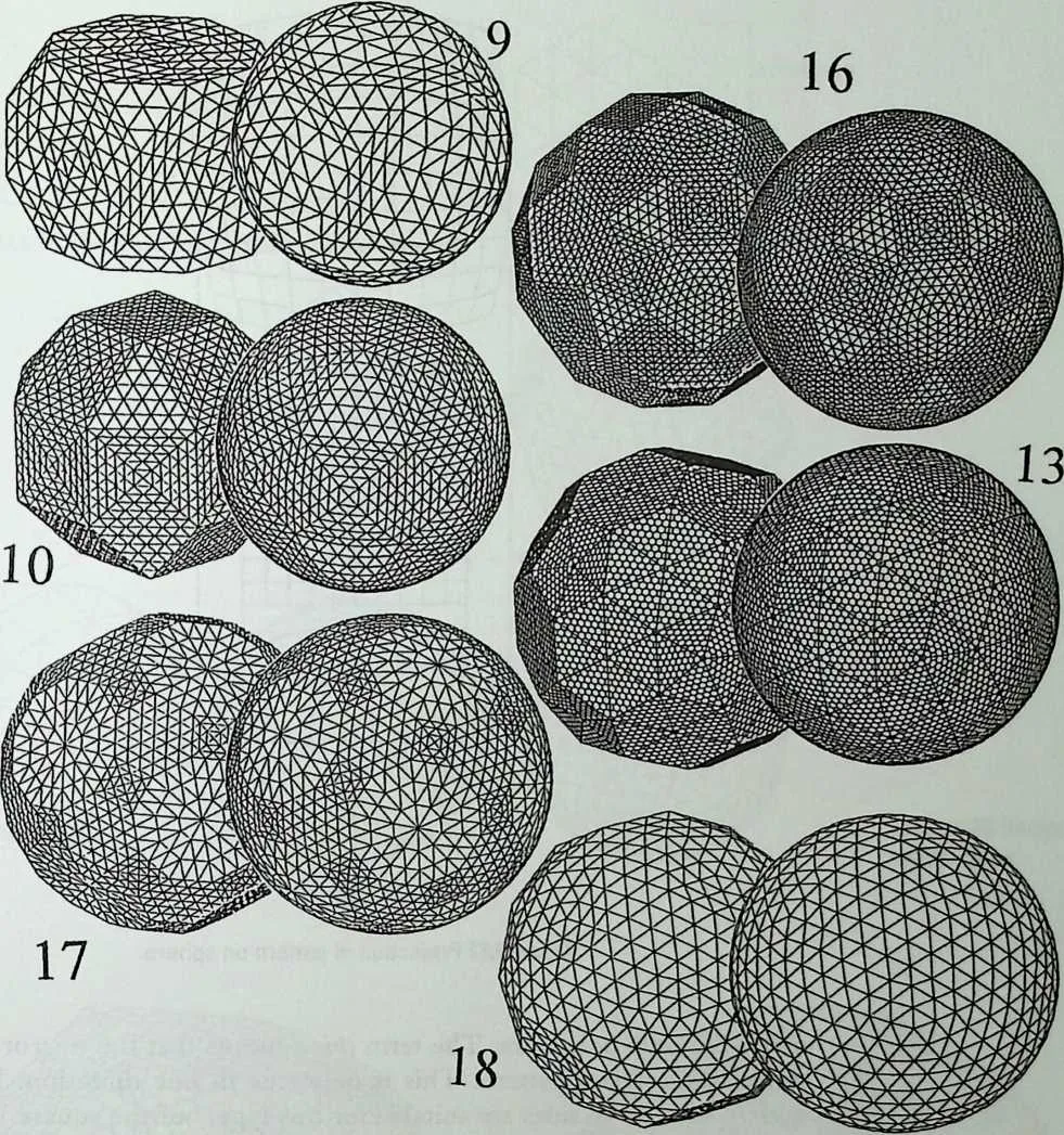
666 Polygonal Subdivisions. Similar kinds of subdivisions can be made on any of the other regular and semi-regular solids. Even their reciprocals as well as regular prisms and antiprisms can be used this way, as long as they are properly subdivided.19,22,23 Subdivision patterns are written on the faces of these figures and the coordinates of the intersection points can be converted from Cartesian into polar coordinates. If all distances are then taken equal to the radius of the circumscribed circle, the originally polyhedric form is turned into a sphere. The spherical coordinates can also be written in a general form, so that the shape of the sphere can be modified.
667 It was previously mentioned that the polyhedra considered here are composed of polygons with 3, 4, 5, 6, 8, or 10 sides. In the literature one discerns mainly three so-called classes of subdivision of the triangular faces; see, for example, Ki trick.18 Class I is the basic subdivision type for triangles and is generally used in combination with icosahedra (only rarely with octahedra); Class II is, in fact, reciprocal (the rhombic triacontahedron); and Class III is the snub dodecahedron type (P18 in Figure 9.3).
668 The subdivision of the polygons can be worked out more or less analogously to the general concept used by Kitrick et al. (Figures 9.32 to 9.36).
669 Class I: Radial Type. The triangle is taken as the starting point. This can be subdivided into smaller triangles. Two basically different methods are in use: edge based and arch based. The polygon is first subdivided into its own plane and each intersection is projected radially onto the sphere (Figure 9.37). In the next part, byway of example, triangular patterns with frequencies of 3 or 6 are used and also a particular hexagonal pattern. This equilateral triangle can be
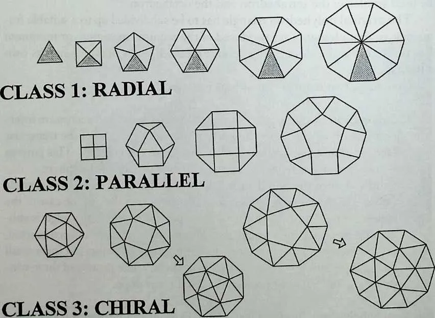
672673Figure 9.32 Three kinds of subdivision of polygons.
674 Figure 9.33 Further breakdown of the polygons.
675 Figure 9.34 P7 with hexagonal pattern, pumped up to spherical form.
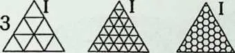
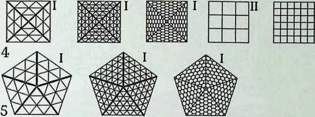
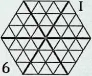
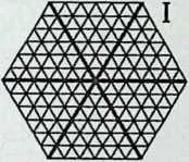
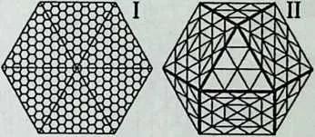
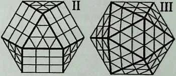
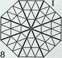
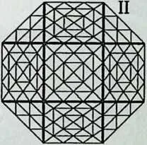
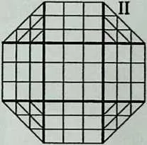
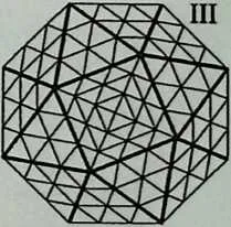
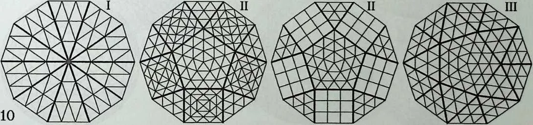
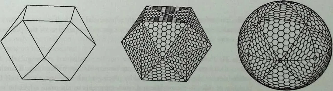
678 Figure 9.35 Examples of polyhedral breakdowns of spherical surfaces, based on the Platonic solids.
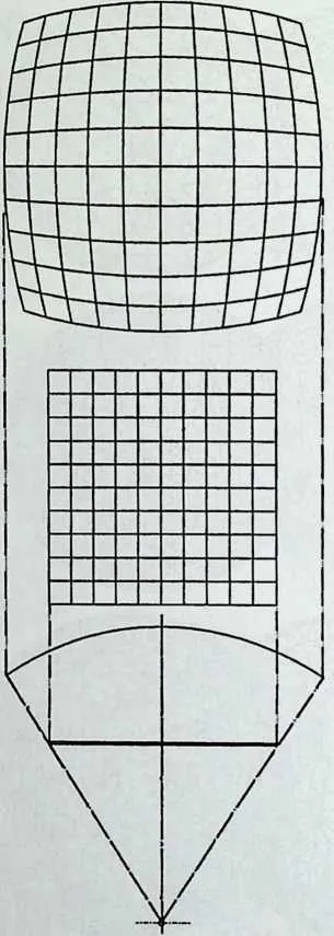
679 shifted, transformed, and subsequently reproduced by rotation around the axis perpendicular to its plane in order to fill the radial patterns of the polygons with more than three sides.
680 Class II: Parallel Type. The square can be subdivided rectangularly, for instance into smaller squares. These can be provided with diagonals. A further subdivision of the polygon is found by placing another polygon with half the number of sides in the middle and connecting this to alternate edges by rectangles. The remaining parts are triangular. The triangular and the rectangu-
683684Figure 9.36 Further examples of breakdowns, based on some of the Archimedean solids.
685 lar parts can be filled in with transformations of the regular versions. The basic polygon must have an even number of sides. The square is trivial and this leaves only the polygons with 6, 8, and 10 sides having a triangle, a square, or a pentagon in the center.
686 Class III: Chiral Type. This is comparable to Class II but with the central—smaller—polygon slightly rotated over the angle ir/n (n is the number of the sides). The remaining part can be made up of smaller triangles, which can again be subdivided. If seen from above, this type recalls very
688 Figure 9.37 Projection of pattern on sphere.
689 much the snub polyhedra. The term chiral means that the mirror image is unlike the original pattern. This is only true in one direction. Polygons with 4, 6, 8, or 10 sides are suitable for this type, but the square leads to a somewhat trivial solution.
690 Reciprocal Sphere Subdivisions
691 The dual or reciprocal versions of the polyhedra can also be further subdivided (Figures 9.38 and 9.39). This is easily understandable for those that have a triangular composition, such as those with the numbers Rl, 2, 4, 6, 8, 9, 11, 13,14, and 17. These do not particularly throw a new light on the subject, but there are two others that are much more interesting in this respect: R7 and R12, or the rhombic dodecahedron and triacontahedron. R3 (cube), which can be considered as the dual of the octahedron, also belongs to the category of rhombic polyhedra by analogy. So there are three reciprocals that act as the counterparts of the three triangular regular polyhedra. The subdivision of the spherical surface is accomplished in this group in a way similar to the Class H triangle.
693 Figure 9.38 Reciprocal subdivisions.
696697Figure 9.39 Hexagonal geodesic, based on R12.
698 Modifications of the Sphere
699 The shape of the sphere can be altered in many ways.4,16,l7,27 The equation of the sphere can be transformed into a set of two expressions, describing it in a more general way:
700 /?, = EJ sin"'4> + cos",(p),/n'
701 /?2 = /?,£/ (£?* sinn20 + Rf2 cos"2'"2
702 where nx and n2 are the exponents of the horizontal and vertical ellipses, respectively, and E1 and E2 are the ratios of their axes (see also Figure 9.40).
703 The curvature is a normal ellipse for m=2, but if n is raised, a form is found that approximates the circumscribed rectangle. If n is decreased, the curvature flattens until 72=1 and the ellipse then has the form of a pure rhombus with straight sides, connecting the maxima on the coordinate axes. For n<\ the curvature becomes concave and obtains a shape reminiscent of a hyperbola. For ?z=0 the figure coincides completely with the X and Y axes.
704 By changing the value of both the horizontal and the vertical exponents, the visual appearance of a hemispherical shape can be altered considerably. The pure sphere forms, in fact, only one specific representation out of a great number of possible shapes that can be formed by a combination of different horizontal and vertical ellipses. Some of these do not even resemble the original convex ellipsoidal shape, yet are very familiar, such as the pyramid, the cone, the cylinder, the cube, and so on.
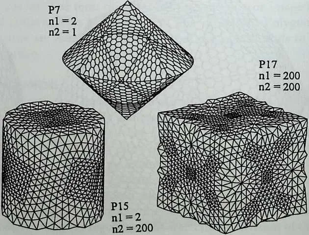
706 If for both ellipses an exponent nx = n2 = 2 is chosen and if the ratio of the axes is kept equal to = E2 = 1, the pure sphere is found. The subdivision of the surface of such an ellipsoidal shape may be based on the same methods described previously. The resulting pattern is projected onto the surface of the ellipsoid from the inside, using the origin as the projection center.
707 Truncation
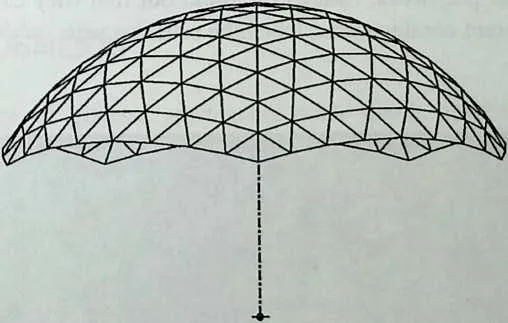
708 For practical purposes, parts of the sphere have often been cut off in order to make it fit on horizontal or against vertical planes. This can be done as demonstrated in Figure 9.41. A certain value for the angle of the desired truncation plane has to be chosen and an area around it where all occurring nodes have to be transferred to this plane in order to obtain a properly closed lower boundary. The pattern itself can be rotated or translated before the projection upon the sphere takes place.
709 Augmentation
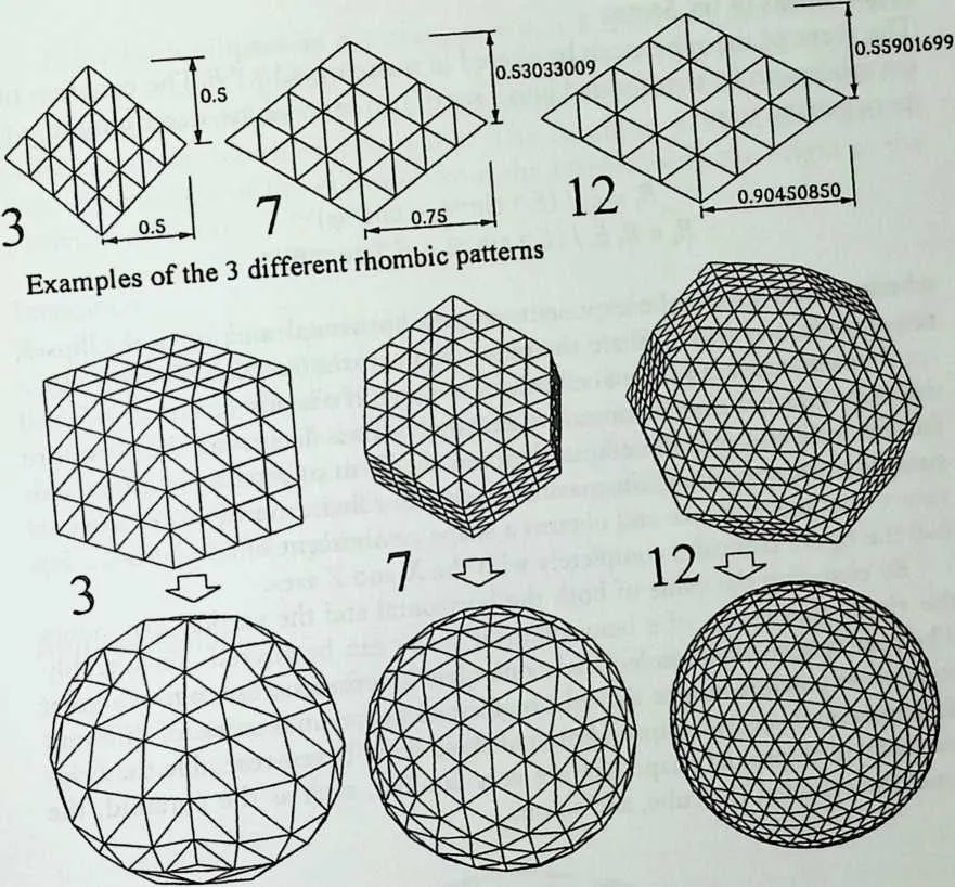
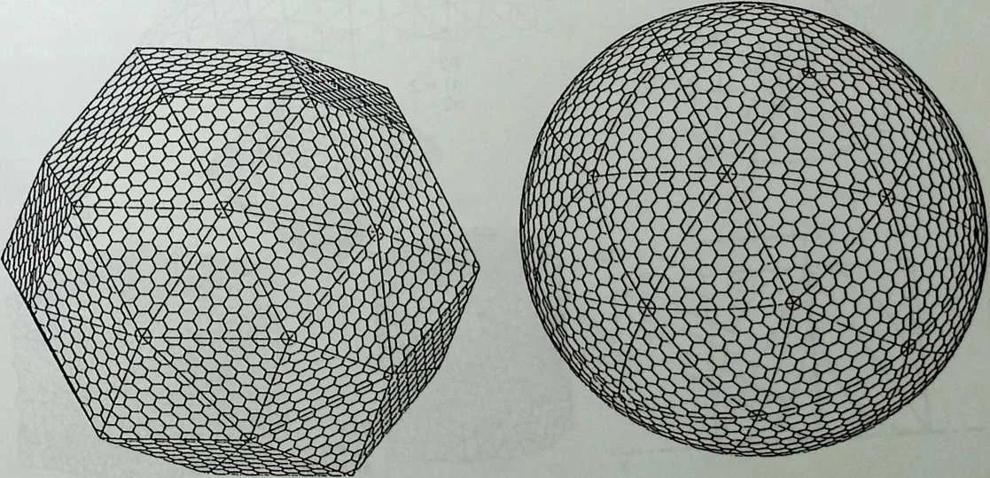
710 Upon the regular faces of the polyhedra other figures can be placed that have the same basis as the respective polygon. In this way polyhedra can—so to speak—be ‘‘pyramidized,’’ as already mentioned earlier. This means that shal-
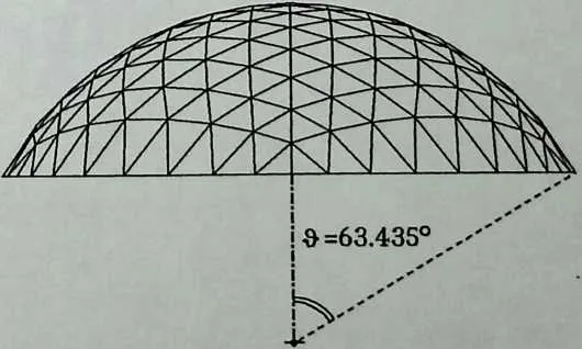
713 Figure 9.41 Truncation and adaptation to horizontal plane.
716717Figure 9.42 Augmented polyhedra.
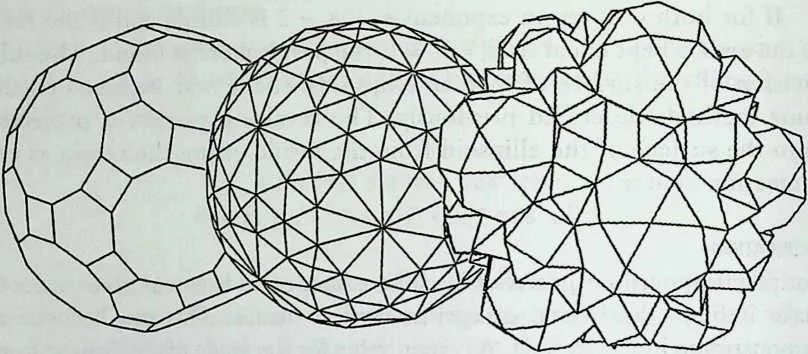
718 low pyramids are put on top of the polyhedral faces, having their apices on the circumscribed sphere of the whole figure. This can be considered as the first frequency subdivision of spheres.
719 In 1582 Simon Stevin introduced the notion of ‘‘augmentation’’ by adding pyramids, consisting of triangles and having a triangle, a square, or a pentagon as a base, to the five regular polyhedra.3 In 1990, the late D.G. Emmerich extended this idea to the semi-regular polyhedra (Figure 9.42). He suggested using pyramids, with 6-, 8-, or 10-sided bases, that are composed of regular polygons. There are seven such pyramids, that are suitable for this purpose and that are, in fact, parts of other polyhedra. Emmerich found out that they can be combined to form 102 different combinations, which he calls composite polyhedral
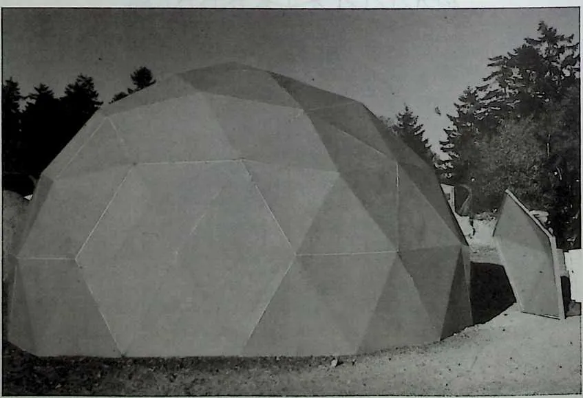
721 Figure 9.43 Structure of pyramidized pentagonal and hexagonal GRP panels.
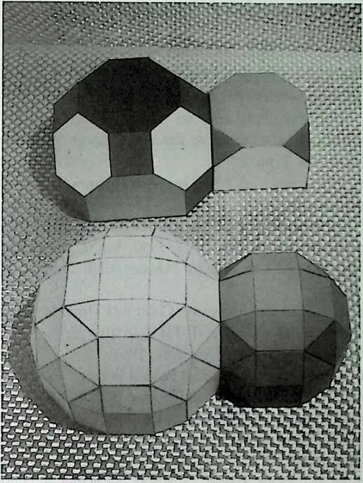
724725Figure 9.44 Model of augmented P9 and P11.
726 ACKNOWLEDGMENTS
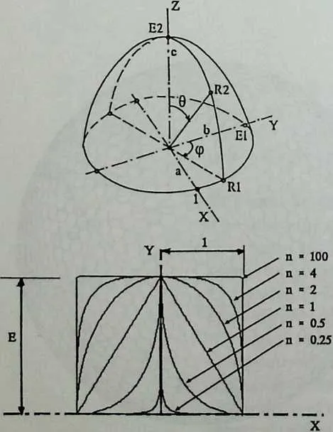
727 The availability of general approaches with which polyhedra and related forms can be described so that they become visible and tangible is very important. The computer is a substantial help in reaching this goal. Some of the shapes generated remind one of crystalline elements or aggregates of composite materials. There appears to be great similarity in the way in which structural elements or systems as a whole are described. Both environments can be approached using one comprehensive method only. The application of physical properties to such micro or macro structures opens the way to their interactive design and also to the computer-aided production of the constituent members.
728 Most of the figures in this chapter have been made with the help of the computer program CORELLI, which is being developed by the author in close cooperation with Gerrit van der Ende.13,22,25
9.3 NOTES
- 1.
- H. S. M. Coxeter et al., ‘‘Uniform Polyhedra,’’ Philosophical Transactions of the Royal Society of London, Series A, Vol. 246, 1954, pp. 401450.
- 2.
- L. A. Lyustemik, Convex Figures and Polyhedra, Dover, New York.
- 3.
- D. J. Struik, The Principal Works of Simon Stevin, Vol. 2, Swets en Seitlinger, Amsterdam, 1958.
- 4.
- P. Huybers, ‘‘De Geometri van Uniforme Polyeders’’ (The Geometry of Uniform Polyhedra), TUD-Report 10–76–1, Delft, 1976.
- 5.
- P. Huybers, ‘‘The Snub Polyhedra on Closer Examination,’’ Proceedings of the IASS-CSCE International Congress on Innovative Large Span Structures, Toronto, July 12–17, 1992, Vol. 2, pp. 2910.
- 6.
- M. Bruckner, Vielecke and Vielfliiche, Theorie und Geschichte, Druck und Verlag von B. G. Teubner, Leipzig, 1900.
- 7.
- P. Huybers, ‘‘The geometry of the Dual Uniform Solids,’’ First International Seminar on Structural Morphology, Sept. 7–11, 1992, Vol. 2, pp. 1–11.
- 8.
- T. Roman, Regulate und halb-regulare Polyeder, VEB Deutsche Verlag der Wis-senschaften, Berlin.
- 9.
- A. Holden, Shapes, Space and Symmetry, Columbia University Press, 1971.
- 10.
- J. Kepler, Harmonices Mundi, Liber II (1571–1630).
- 11.
- L. Lines, Solid Geometry, Dover, New York, 1965.
- 12.
- O. L. Tonon, ‘‘Geometry of the Spatial Folded Forms,’’ Fourth Conference on Space Structures, Sept. 5–10, 1993, Guildford, England, pp. 2042–2052.
- 13.
- P. Huybers and G. van der Ende, ‘‘Prisms and Antiprisms,’’ Proceedings of the International IASS Conference on Spatial, Lattice and Tension Structures, Atlanta, April 24–28, 1994, pp. 142–151.
- 14.
- R. Sheppard et al., Paper Houses, Survival Scrapbook 4, Unicorn Bookshop, Caerffyrdin, USA, 1974.
- 15.
- Domebook, Pacific Domes, London, 1971.
- 16.
- P Huybers, ‘‘Super-Elliptic Geometry as a Design Tool for the Optimization of Dome Structures,’’ in Optimization of Structural Systems and Industrial Applications, S. Hernandez et al., eds., Computational Mechanics Publications and Elsevier, Southampton/London, 1991, pp. 387–399.
- 17.
- P. Huybers, ‘‘About the Manipulation of Spheroidal Forms,’’ Proceedings of the IASS-CSCE International Congress on Innovative Large Span Structures, Toronto, fitly 12–17, 1992, Vol. 2, pp. 55–66.
- 18.
- C. J. Kitrick, ‘‘A Unified Approach to Class I, II & DI Geodesic Domes,’’ International Journal of Space Structures, Vol. 5, No. 3/4, 1990, pp. 223–246.
- 19.
- H. Lalvani, ‘‘Continuous Transformations of Subdivided Periodic Stirfaces,’’ International Journal of Space Structures, Vol. 5, No. 3/4, 1990, pp. 255–279.
- 20.
- A. Pugh, Polyhedra, a Visual Approach, University of California Press, 1976.
- 21.
- J. D. Clinton, ‘‘Advanced Structural Geometry Studies,’’ NASA Contract Report CR.1735.
- 22.
- P. Huybers and G. van der Ende, ‘‘Polyhedral Sphere Subdivisions,’’ Proceedings of the IASS Conference on Spatial Structures: Heritage, Present and Future, Milan, fine 5–9, 1995, pp. 189–198.
- 23.
- H. Nooshin and D. Tzourmakliotou, ‘‘An Approach for Generation of Geodesic Forms,’’ Fourth International Conference on Space Structures, Guildford, Sept. 6–10, 1993, pp. 1085–1096.
- 24.
- D. G. Emmerich, ‘‘Composite Polyhedra,’’ International Journal of Space Structures, Vol. 5, No. 3/4, 1990, pp. 281–296.
- 25.
- P. Huybers, ‘‘The Formation of Polyhedra by the Rotation of Polygons,’’ Fourth
731International Conference on Space Structures, Guildford, Sept. 6–10, 1993, pp. 1097–1108.
- 26.
- P. Huybers, ‘‘Dome-Type Space Structures of Ellipsoidal Form, International Journal of Space Structures, Vol. 5, No. 3/4, 1990, pp. 297–308.
- 27.
- H. Kenner, Geodesic Math and How to Use It, University of California Press, London, 1976.
733 10