
12 Computer-Aided Processing of Polyhedric Configurations
2Hoshyar Nooshin, P. L. Disney, and O. G. Champion
12.1 INTRODUCTION
3The objective of this chapter is to establish a methodology on which computer-aided techniques for the processing of polyhedric configurations may be based. The term polyhedric configuration is used to refer to any geometric arrangement that is based on polyhedra. In particular, the focus of attention is on polyhedric configurations that are of importance in the architectural and structural engineering fields.
4 The natural medium for the processing of polyhedric configurations is a programming language that incorporates the concepts of formex algebra. Formian is such a programming language in which the processing of polyhedric configurations can be carried out using the standard elements of the language.1 The term processing of polyhedric configurations in the present context
5 Beyond the Cube: The Architecture of Space Frames and Polyhedra, edited by J. Francois Gabriel ISBN 0–471–12261–0 © 1997 John Wiley & Sons, Inc.
6 □ 343
7 simply means the creation and manipulation of polyhedric configurations.
8 The actual usage of the ideas presented in this chapter is envisaged to be through a programming language such as Formian. However, the main body of the material presented is independent of any particular mathematical system or computer software. The emphasis is on the primary concepts that are fundamental for the processing of polyhedric configurations in any medium.
9 The approach used in presenting the material is to begin by exploring the basic classes of polyhedric configurations. This is followed by a review of the properties of two families of polyhedra that are of central importance in relation to polyhedric configurations. The rest of the chapter is devoted to describing the basic procedures for processing of polyhedric configurations.
11 Polyhedra have been the subject of fascination and interest since ancient times. They have been studied throughout the ages by mathematicians, philosophers, and artists and they play an important role in a number of branches of science and technology.
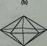
12 The interest in polyhedra in this chapter stems from the fact that they provide a basis for the generation of a number of important classes of structural forms. Examples of polyhedra that are of particular interest in the present chapter are shown in Figure 12.1. These are the tetrahedron, octahedron, dodecahedron, icosahedron, and cuboctahedron, where
- the tetrahedron has four triangular faces,
- the octahedron has eight triangular faces,
- the dodecahedron has 12 pentagonal faces,
- the icosahedron has 20 triangular faces, and
- the cuboctahedron has eight triangular faces and six square faces.
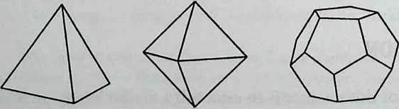
1516(a) Tetrahedron (b) Octahedron (c) Dodecahedron
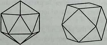
18 (d) Icosahedron (e) Cuboctahedron
19 Figure 12.1 Some basic polyhedra.
20  vavavavA.
21 ▼avavavaWj
22 3TAVaVaWaVa<.
23 »kVAVATAVAVAW< 1
24 ▼avavatavavavavAs?
2627jAVAVAVAVAWAVAVAVA
28WavavavaWavavava, ;
29
▼avavavavavavavavavavJ
30 (b)
31 Figure 12.2 Mapping onto faces of an icosahedron.
32 MAPPING ONTO FACES OF POLYHEDRA
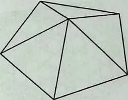
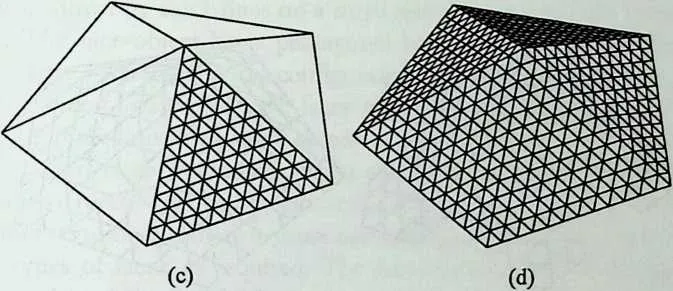
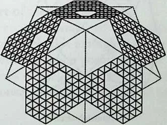
33 The first class of polyhedric configurations to be considered is obtained by placing objects onto the faces of polyhedra. For example, the configuration shown in Figure 12.24? is a polyhedric configuration that is obtained by placing a triangulated pattern on five faces of an icosahedron. A configuration that is used for mapping onto the faces of a polyhedron is referred to as a face-object. The face-object in the example under consideration is shown in Figure 12.2a. Also, the faces of the icosahedron that are to be mapped onto are shown in Figure 12.2b. These faces are shown again in Figure 12.2c, with one of them having the face-object placed onto it. The complete arrangement with the face-object mapped onto all five faces is shown in Figure 12.24?. In the preceding description of the procedure for obtaining a polyhedric configuration, the terms mapping and placing have been used interchangeably. This is appro-
3637Figure 12.3 Mapping with different face-objects.
38 priate because mapping in the present context simply means placing.
39 Another example of a polyhedric configuration is shown in Figure 12.2/ This configuration is obtained using the same procedure as described previously. However, in this case, a different face-object is used for mapping. The new face-object is shown in Figure 12.2e and the boundaries of one of the faces of the icosahedron on which the face-object is mapped are shown by dotted lines in Figure 12.2/
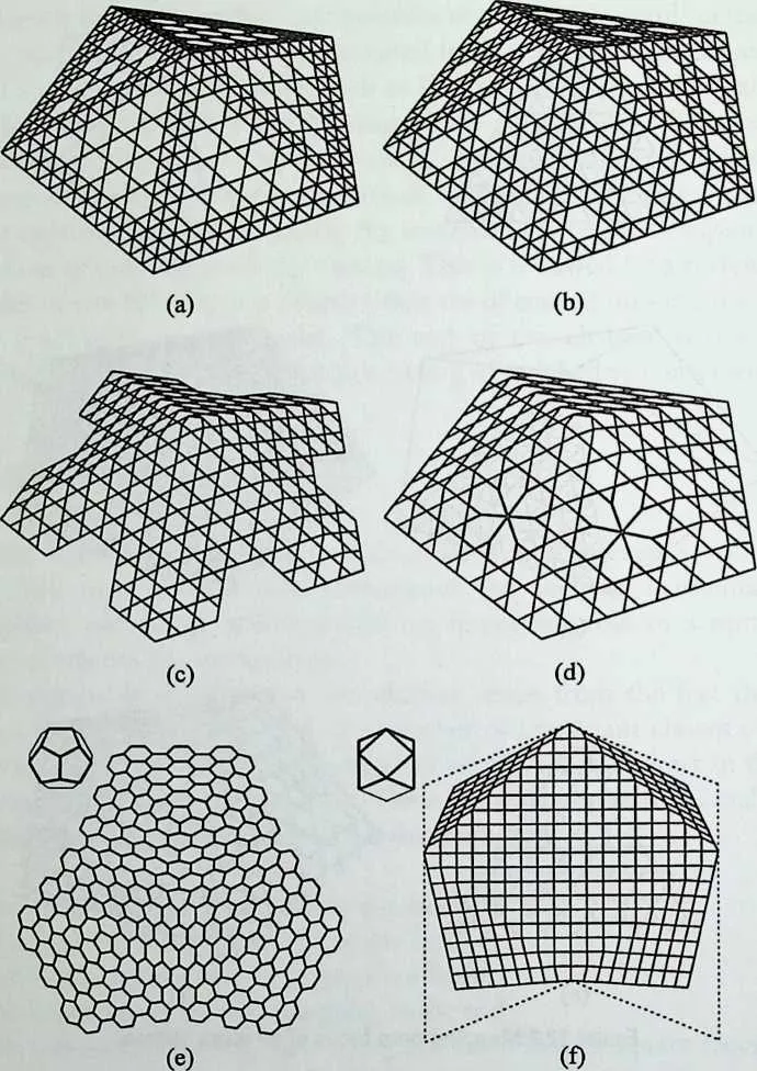
40 Further examples of polyhedric configurations that are obtained by face mapping are shown in Figure 12.3. The configurations shown in Figures 12.3/z—d are obtained by mapping different face-objects onto five faces of an icosahedron. The point illustrated by these configurations is that face-objects are not limited to simple primary patterns and one is free to choose any required pattern for mapping. The polyhedric configuration shown in Figure
41 12.3c illustrates the fact that a face-object need not necessarily ‘‘match’’ the boundaries of the faces onto which it is mapped. Indeed, in general, a faceobject may only partially ‘‘fill’’ a face or may extend beyond a face. The point illustrated by Figure 12.3 d is that a polyhedric configuration may involve more than one type of face-object. In the configuration of Figure 12.3d, three faces have a face-object with a uniform pattern and two faces have a faceobject with openings that create a ‘‘daisy window’’ effect.
42 Figure 12.3e shows a polyhedric configuration that is obtained by mapping a face-object onto three neighboring faces of a dodecahedron. These faces are shown by thick lines on a small sketch at the top left comer of the figure. The face-object has a pentagonal boundary with internal hexagonal subdivisions. The polyhedric configuration of Figure 12.3/ is obtained by mapping face-objects onto five faces of a cuboctahedron. These faces are shown by thick lines on a small sketch at the top left comer of the figure. A new situation is encountered here in that the faces are of different types. Namely, there are four triangular faces and one square face. This, however, does not create any problem because one can use different face-objects for different types of faces, as required. The face-objects used for the polyhedric configuration of Figure 12.3/are a square-shaped face-object for the top face and a triangular face-object for the four side faces. It is to be noted, however, that the triangular face-object used does not fill the side faces. This fact is indicated in Figure 12.3/ where the actual boundaries of the side faces are shown by dotted lines.
43 The polyhedric configurations shown in Figures 12.2 and 12.3 are samples of a wide variety of configurations that may be created by mapping different face-objects onto the faces of polyhedra. These polyhedric configurations constitute an important class of structural forms. In addition, they provide the bases for the creation of geodesic forms, as will be discussed later.
44 MAPPING ON EDGES OF POLYHEDRA
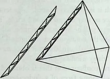
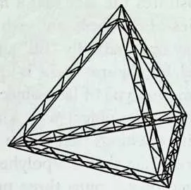
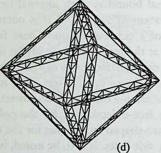
45 The constitution of a polyhedron may be perceived in different ways. A tetrahedron, for example, may be regarded as a solid body with four faces, six edges, and four vertices. Alternatively, it may be regarded as a ‘‘stick arrangement’’ consisting of six line segments (sticks) that meet at the vertices. With this new way of visualizing a tetrahedron, one can again recognize four faces, six edges, and four vertices. Another way of perceiving a tetrahedron is to think of it as a basis for mapping. Thus the tetrahedron is regarded as a ‘‘geometric jig’’ that has four faces, six edges, and four vertices and is used for the positioning of mapping objects. This way of perceiving a polyhedron is helpful in visualizing the process of mapping face-objects as described in the previous section. This point of view is also useful for visualizing the mapping of objects on the edges of polyhedra. Mapping on the edges of polyhedra is the production mechanism for a major class of polyhedric configurations. Examples of this kind of configuration are shown in Figure 12.4.
47 Figure 12.4 Mapping on edges of polyhedra.
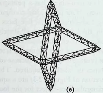
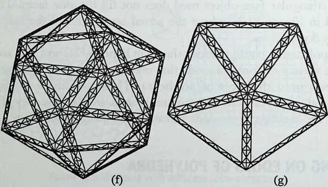
48 Figure 12.4c shows a polyhedric configuration that is obtained by mapping (placing) a space truss configuration on the edges of a tetrahedron. A configuration that is used for mapping on the edges of a polyhedron is referred to as an edge-object. The edge-object in the example under consideration is shown in Figure 12.4/z. Also, the edges of the tetrahedron with the edge-object mapped on one of them is shown in Figure 12.4Z>. In this example the ends of the edgeobject are shaped such that when it is mapped on the edges of the tetrahedron the ends match with one another at the vertices. Figure 12.4// shows a polyhedric configuration that is obtained by mapping a space truss configuration on the edges of an octahedron. The ends of the edge-object are again suitably shaped such that they match with one another after mapping. Figure 12.4e illustrates the fact that the mapping of an edge-object need not necessarily involve all the edges of a polyhedron. In the case of the polyhedric configuration of Figure 12.4e, the edge-object is mapped on eight edges of an octahedron. In Figure 12 Af an icosahedron has been used as the basis for mapping. The edgeobject is again a space truss with its ends suitably shaped. The same edge-object is used to produce the polyhedric configuration of Figure 12.4g. In this case a group of 10 edges of an icosahedron is used for the operation.
49 The pioneering work of Gabriel involves a number of examples of polyhedric configurations of the type described above.2,3
50 MAPPING ON VERTICES OF POLYHEDRA
51 The idea of mapping objects on the vertices of polyhedra is a natural extension of the processes of mapping objects on the faces and edges of polyhedra. Examples of polyhedric configurations that are obtained by mapping objects on the vertices of polyhedra are shown in Figure 12.5.
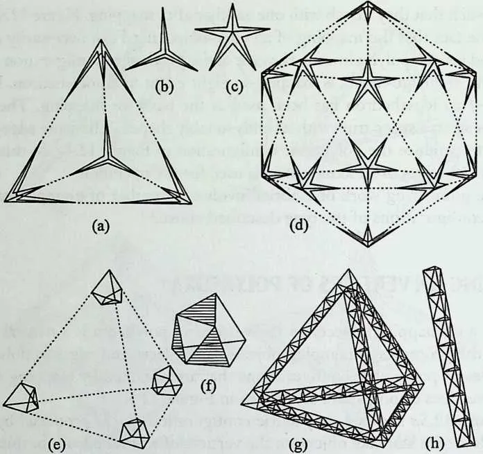
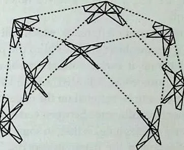
52 Figure 12.5a shows a polyhedric configuration that is produced by mapping (placing) a star-like object on the vertices of a tetrahedron. In this figure the dotted lines indicate the positions of the edges of the tetrahedron. A configuration that is used for mapping on the vertices of a polyhedron is referred to as a vertex-object. The vertex-object used for the creation of the polyhedric configuration of Figure 12 .Sa is shown in Figure 12.5&. A similar operation is performed to produce the configuration of Figure 12.5 J using an icosahedron as the basis. The vertex-object is shown in Figure 12.5c.
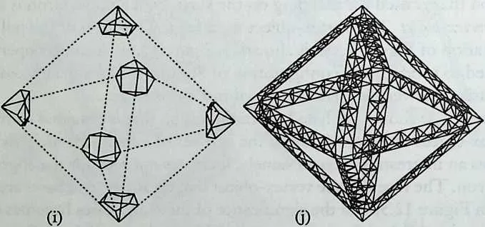
53 Figure 12.5e shows a polyhedric configuration that is obtained by mapping the vertex-object of Figure 12.5/on the vertices of a tetrahedron. This vertexobject has an interesting effect. Namely, it creates end bases for the edges of the tetrahedron. The facets of the vertex-object that create the end bases are shown shaded in Figure 12.5f and the significance of these end bases becomes clear in relation to the polyhedric configuration of Figure 12.5g. This configuration is obtained by a combination of vertex mapping and edge mapping. To elaborate, a smaller version of the vertex-object of Figure 12.5/is mapped on the vertices of a tetrahedron. This is followed by mapping the space truss configuration of Figure 12.5h on the edges of the tetrahedron. The scale and position of this edge-object are chosen such that the ends of the space trusses fit the triangular bases created by the vertex-object. A similar procedure is followed in producing the polyhedric configuration of Figures 12.Si xn&j. In this case an octahedron has been used as the basis for the operation.
54 The technique employed to create the polyhedric configurations of Figures 12.5g and/ can be of value in some practical applications. The technique provides an alternative way of dealing with the ‘‘end matching’’ problem. Thus, instead of shaping the ends of the edge-object for matching at the vertices, the vertex-object is designed to act as a connecting medium. This will result in a simpler edge-object because it only requires straightforward ends.
5859Figure 12.5 Mapping on vertices of polyhedra.
60 Another point that is illustrated by Figures 12.5g andy is worth highlighting. Namely, a polyhedric configuration may involve a combination of edge and vertex mappings. Indeed, in general, there is no restriction regarding the mixing of different types of mappings and any combination of face, edge, and vertex mappings may be used without any problem.
62 The configuration shown in Figure 12.6a is obtained by projecting the configuration of Figure 12.2 onto the surface of a sphere. The sphere is concentric with the icosahedron on which the configuration of Figure 12.2d is based.
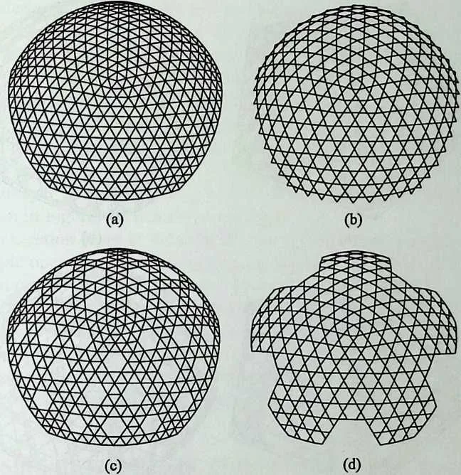
64 Figure 12.6 Some geodesic forms.
65 This common center of the sphere and icosahedron is also chosen as the center of projection. A polyhedric configuration of the type shown in Figure 12.6a is referred to as a geodesic form or geodesic configuration. The same procedure is used to produce the geodesic configurations shown in Figures 12.6b-d. These configurations are obtained using the polyhedric configurations of Figures 12.2f and 12.3£ and c as the bases for projection.
66 The surface on which a geodesic form is produced need not necessarily be spherical. Indeed, a variety of different surfaces such as ellipsoids and paraboloids may be used for the creation of geodesic forms. Also, the type of projection need not necessarily be central and other kinds of projections, such as parallel projection, may be used instead.
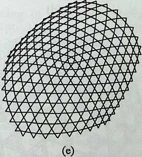
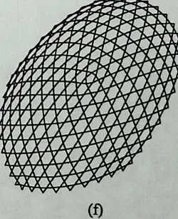
67 Figure 12.6e shows a geodesic form that is obtained by projecting the poly-
7273Figure 12.7 Some double-layer polyhedric configurations.
74 hedric configuration of Figure 12.2/ onto an ellipsoidal surface. A different process is involved in producing the configuration shown in Figure 12.6/ This is obtained by stretching the configuration of Figure 12.6b in one direction.
75 The configuration shown in Figure 12.6/illustrates a point of general importance. Namely, any polyhedric configuration may be subjected to modifications and alterations to suit a particular application. In other words, there is no ‘‘inherent’’ final stage in the processing of a polyhedric configuration. Like a lump of steel in the hands of a blacksmith, a polyhedric configuration may be worked, in as many stages as required, to turn it into a desired shape.
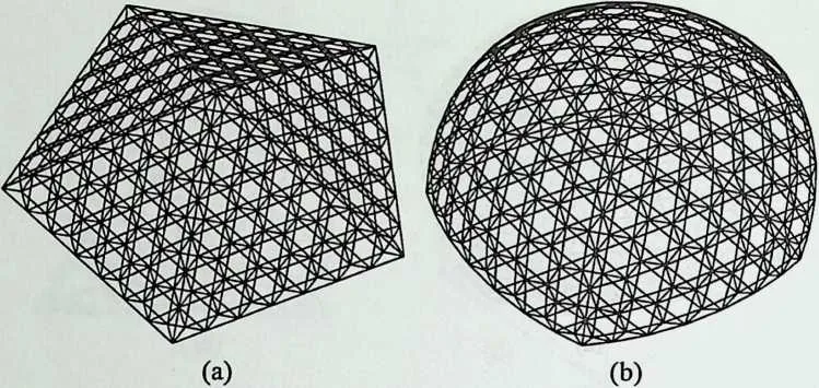
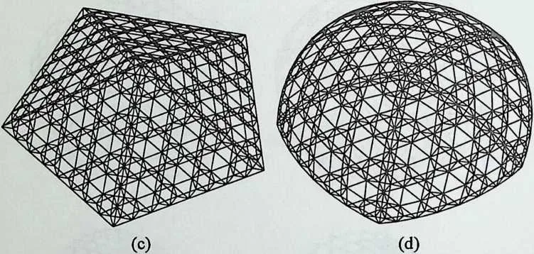
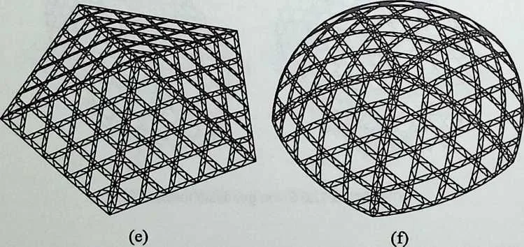
76 A geodesic form may involve two or more layers. For example, the geodesic configuration shown in Figure 12 .lb has two layers of elements that are interconnected together by intermediate web elements. This double-layer geodesic form is based on the configuration shown in Figure 12.7/z. This is a polyhedric configuration that is obtained by mapping (placing) a double-layer face-object onto five faces of an icosahedron. The geodesic form of Figure 12.1 b is obtained by projecting the two layers of the configuration of Figure 12.7/z onto two concentric spheres. A similar procedure is used in obtaining the double-layer geodesic forms of Figures 12.Id and/from the configurations shown in Figures 12.7c and e, respectively.
77 The projection stage in the creation of a geodesic form involves a relatively simple operation. This is true for projection on a single surface as well as projection on two or more surfaces. The reason for the simplicity of operation is that projection is a straightforward concept and can easily be dealt with through a standard computer-based routine.4
78 An abundance of structures have been constructed all over the world using various forms of geodesic configurations. These begin with the pioneering work of R. Buckminster Fuller and include many impressive examples.5,6
79 PROCESSING OF POLYHEDRIC CONFIGURATIONS
80 The processing of polyhedric configurations in precomputer days was an extremely difficult task. In spite of this, a number of gifted designers managed to deal with the problem and create many beautiful structures based on polyhedric configurations. The constraint of the processing difficulties, however, did not allow the designers to take full advantage of the whole spectrum of possibilities and their scope remained rather limited. Even today, the processing of polyhedric configurations is mainly carried out using computer programs that lack generality and have many limitations and shortcomings.
81 In contrast, the conceptual methodology that will be presented in this chapter, combined with suitable computer software such as Formian, provides a means for dealing with the processing of any kind of polyhedric configuration with relative ease.
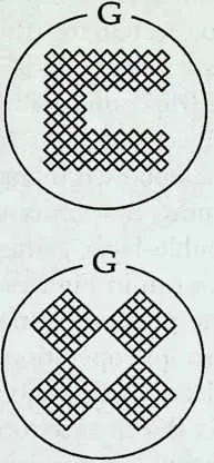
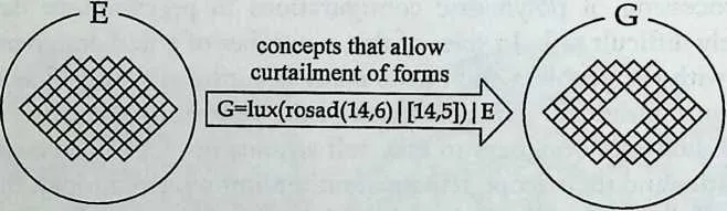
82 One key factor in dealing with the processing of polyhedric configurations is the ability to generate face-objects, edge-objects, and vertex-objects in a convenient manner. The creation of these objects in Formian can be carried out using the concepts of formex algebra. The algebra works through concepts that effect movement, propagation, deformation, and curtailment of forms (Figure 12.8).1,7
83 PLATONIC AND ARCHIMEDEAN POLYHEDRA
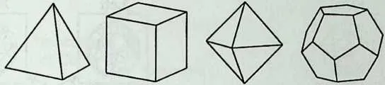
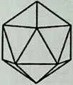
84 In this chapter the use of polyhedra in the creation of structural forms is discussed in terms of Platonic and Archimedean polyhedra. There are five Platonic polyhedra, whose views are shown in Figure 12.9. These five polyhedra
85 Formex algebra includes:
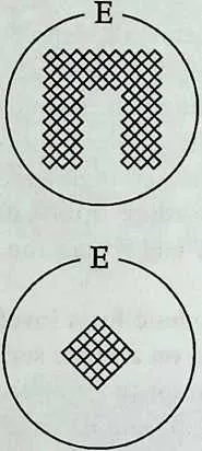
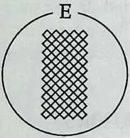
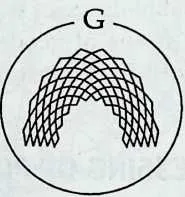
87 concepts that allow movement of forms
88 G=verad(0,0) | E
89 concepts that allow propagation of forms
90 G=lamid(5,5/2)|E
91 concepts that allow deformation of forms G=bb(l,3/2)|bp(l,9)[E \
92 Figure 12.8 Basic concepts of formex algebra.
93 were known to the ancient world before Plato and the designation ‘‘Platonic’’ is due to the fact that Plato paid special attention to these polyhedra.8 Each one of the Platonic polyhedra is a convex body with faces that are congruent regular polygons of the same type.
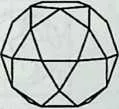
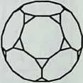
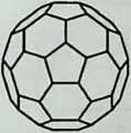
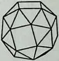
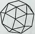
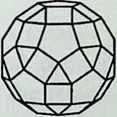
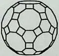
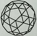
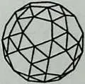
94 An Archimedean polyhedron is also a convex body with faces that are regular polygons. However, unlike the Platonic polyhedra, the faces of an Archimedean polyhedron are not all of the same type. There are 15 Archimedean polyhedra, whose views are shown in Figure 12.9. Each of these polyhedra has either two or three different types of faces. Archimedean polyhedra were discovered in ancient Greece and were described by Archimedes. However, the writings of Archimedes in this regard together with the knowledge of these polyhedra were lost and it was not until the Renaissance that they were gradually rediscovered.8
95 The Platonic and Archimedean polyhedra are closely related and a family tree indicating the relationships between them is shown in Figure 12.10. This
97 PLATONIC POLYHEDRA
98 Pl: Tetrahedron P2: Cube P3: Octahedron P4: Dodeca
99 PS: Icosa
100 hedron hedron
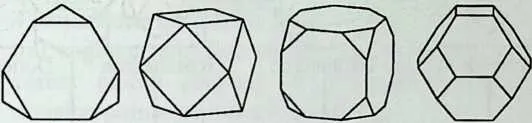
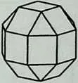
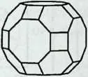
102 ARCHIMEDEAN POLYHEDRA
103 P6: Truncated P7: Cubocta-
104 Tetrahedron
105 hedron
106 P8: Truncated P9: Truncated
107 Cube Octahedron
108 PIO: Small Rhombicub-octahedron
109 Pl 1: Great Rhombicub-octahedron
110 P12: Icosido-decahedron
111 P13: Truncated
112 Dodecahedron
113 P14: Truncated
114 Icosahedron
115 P15: Left
116 Snub Cube
117 P16: Right
118 Snub Cube
119 P17: Small Rhombicosi-dodecahedron
120 P18: Great Rhombicosi-dodecahedron
121 P19:Left Snub Dodecahedron
122 P20: Right Snub Dodecahedron
123 Figure 12.9 Platonic and Archimedean polyhedra.
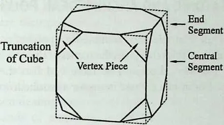
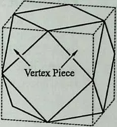
124 is a modified version of a family tree produced by Motro.5 It is seen from Figure 12.10 that the tetrahedron is the ‘‘mother polyhedron’’ and all the other Platonic and Archimedean polyhedra may be derived from it. This may be done through five basic transformations, which are briefly described in Figure 12.11. These transformations are referred to as truncation, canting, snubbing, duality, and planing. Detailed general descriptions of Platonic and Archimedean polyhedra may be found in many excellent publications.8'10
125 POLYHEDRON CODES AND P-NAMES
126 A numeric code is required for identification of the Platonic and Archimedean polyhedra in computer-based procedures for the processing of polyhedric configurations. This numeric code is chosen to consist of the integer numbers 1 to 20, associated with the Platonic and Archimedean polyhedra in the order
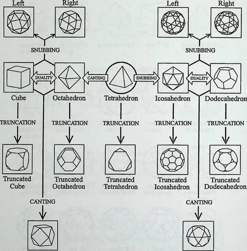
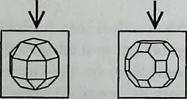
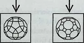
128 Figure 12.10 Family tree of Platonic and Archimedean polyhedra.
129 Snub Cubes
130 Snub Dodecahedra
131 Cuboctahedron
132 Icosidodecahedron
133 Great
134 CANTING + PLANING
135 TRUNCATION + PLANING
136 Small
137 Rhombicuboctahedron
138 Great
139 CANTING + PLANING
140 TRUNCATION + PLANING
141 Small
142 Rhombicosidodecahedron
143 they appear in Figure 12.9. These identity numbers are referred to as polyhedron codes. For instance, the polyhedron codes for the tetrahedron, cuboctahedron, and icosidodecahedron are 1, 7, and 12, respectively. A polyhedron code, preceded by the letter P, is used as an alternative name for the polyhedron. A name of this form is referred to as a P-name. The P-names of the Platonic and Archimedean polyhedra are shown in Figure 12.9 together with the traditional names of the polyhedra. In the following material the P-names are sometimes used by themselves or together with the traditional names to identify polyhedra.
145 Canting of Cube
146 Truncation: Each edge is divided into a central segment and two end segments and the vertex pieces obtained by connecting the division points are cut off, as shown.
147 Canting: Each edge is divided into two equal segments and the vertex pieces obtained by connecting the division points are cut off, as shown.
148 Snubbing of Cube
149 Dual of Cube
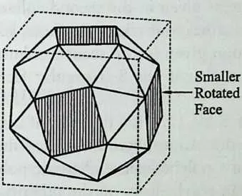
150 Snubbing: A smaller rotated version of each face is placed centrally on the face (shown shaded) and the regions between the edges of the new faces are trimmed off by faceting.
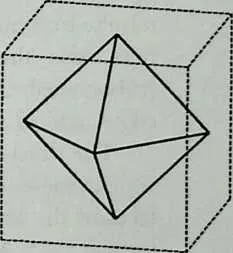
151 Duality: The center of each face is regarded as the vertex of another polyhedron (or each vertex is regarded as the center of a face of a polyhedron).
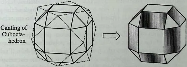
152 Planing of Canted Cuboctahedron
153 Planing: The term ‘planing’ implies ‘planing down’ (scraping off) the surface of a polyhedron. For instance, in producing the small rhombicuboctahedron, a cuboctahedron is subjected to canting, as shown above. This will give rise to a polyhedron that is similar to the small rhombicuboctahedron but in which the faces that are shown shaded are rectangular rather than square. To overcome the problem, the shaded rectangular faces together with the triangular faces are planed down to a depth that equalizes all the edges.
154 Figure 12.11 Truncation, canting, snubbing, duality, and planing.
155 PROPERTIES OF PLATONIC AND ARCHIMEDEAN POLYHEDRA
157158The basic particulars of the Platonic and Archimedean polyhedra are given in Table 12.1. The first column of this table gives the names of the polyhedra together with their P-names. The second column of Table 12.1 fists the numbers of faces, edges, and vertices. For instance, these items for a tetrahedron are given as
159 F3:4
160 F:6
I/: 4
162163Here, the letter F stands for face and the digit that follows F indicates the number of sides of the face. Also, the letter E stands for edge and the letter V stands for vertex. The items given in the second column of Table 12.1 for a tetrahedron indicate that it has four triangular faces, six edges, and four vertices. Also, the information given in the second column of the table for P7 (cuboctahedron) indicates that it has 8 triangular faces, 6 square faces, 24 edges, and 12 vertices.
164The third column of Table 12.1 lists the radii of inspheres of the Platonic and Archimedean polyhedra. An insphere is a sphere that is tangent to all the faces of the same type of a polyhedron. A Platonic polyhedron has only one insphere. An Archimedean polyhedron, on the other hand, has either two or three inspheres, depending on whether it has two or three different types of faces. The radius of insphere for an Archimedean polyhedron given in the third column of Table 12.1 corresponds to the smallest insphere, that is, the insphere that is tangent to the largest faces. Also included at the end of Table 12.1 are two general formulas for evaluation of the radii of inspheres for Platonic and Archimedean polyhedra. Each value in the third column of Table 12.1 is given in terms of a parameter L that represents the edge length of the polyhedron.
165The parameter L, representing the edge length, also appears in columns 4 and 5 of Table 12.1. Columns 4 and 5 list the radii of interspheres and cir-cumspheres of the Platonic and Archimedean polyhedra. An intersphere is a sphere that is tangent to all the edges of a polyhedron and a circumsphere is a sphere that passes through all the vertices of a polyhedron. Each Platonic or Archimedean polyhedron has one intersphere and one circumsphere.
166The last column of Table 12.1 lists the dihedral angles of the Platonic and Archimedean polyhedra. A dihedral angle is the angle between two faces of a polyhedron that share an edge. For any Platonic polyhedron, all the dihedral angles are equal. In contrast, an Archimedean polyhedron may have up to three different dihedral angles, as shown in the last column of Table 12.1. For an Archimedean polyhedron that has more than one dihedral angle, the faces that correspond to each dihedral angle are specified by the numbers of their sides given in square brackets. For example, in the case of P6 (truncated tetrahedron), the first dihedral angle is preceded by [6—6] indicating that the angle is between two hexagonal faces and the second dihedral angle is preceded by [6–3] indicating that the angle is between a hexagonal face and a triangular face.
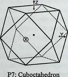
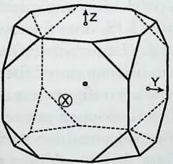
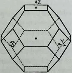
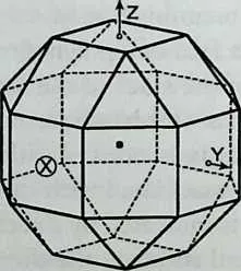
167The properties of the Platonic and Archimedean polyhedra, as given in Table 12.1, are incorporated into the part of Formian that deals with the processing of polyhedric configurations. The information is built into Formian in terms of the formulas given in Table 12.1. The use of formulas will allow the full available accuracy of the computer to be utilized. High accuracy of the basic polyhedral data is essential in many situations. This is the case, for instance, when dealing with complex polyhedric configurations that consist of many thousands of elements, in particular, when the generated geometric details are to be used as a basis for other operations, such as structural analysis.
168In regard to the accuracy of the entries in Table 12.1, it should be noted that for the snub polyhedra (P15, P16, P19, and P20), the accuracy of the entries for radii of insphere, intersphere, and circumsphere depends on the accuracy of a parameter k. The value of this parameter in Table 12.1 is given accurate to nine decimal places. The values of the dihedral angles for the snub polyhedra in Table 12.1 are also given accurate to nine decimal places.
169 POLYHEDRAL COORDINATE SYSTEMS
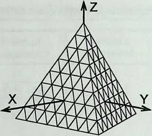
171172A view of a polyhedric configuration is shown in Figure 12.12/z. The configuration is obtained by mapping a triangulated pattern onto the faces of a tetrahedron. When a computer-aided approach is used in processing such a configuration, the internal computer representation of the configuration will be a numerical model that describes the configuration in terms of the coordinates of its nodal points. It is therefore necessary to have a coordinate system with respect to which the nodal coordinates are specified. The most convenient approach in this regard is to establish a standard coordinate system for the tetrahedron and to use it for all polyhedric configurations that are based on a tetrahedron.
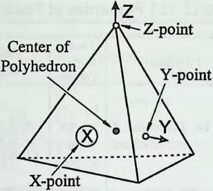
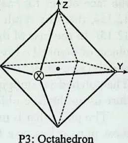
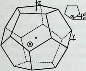
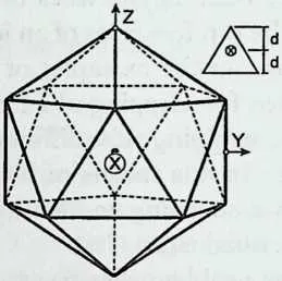
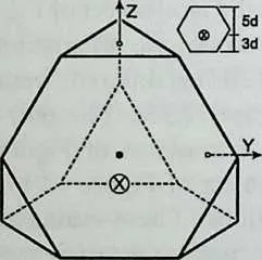
173The chosen standard coordinate system for the tetrahedron is the right- handed Cartesian coordinate system that is shown as X—Y—Z in Figure 12.12a. Figure 12.12# illustrates the conventions used in specifying this standard coordinate system. The origin of the coordinate system is at the center of the polyhedron. This point is indicated by a large dot. The points where the X, Y, and Z axes intersect the body of the polyhedron are referred to as the X-point, Y- point, and Z-point, respectively. The X-point is at the center of the circle with an X inside it. The T-point is indicated by a little circle and the Y axis is shown as an arrow emanating from the K-point. Similarly, the Z-point is indicated by a tittle circle and the Z axis is shown as an arrow emanating from the Z-point.
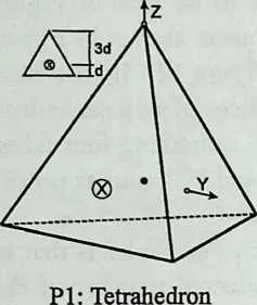
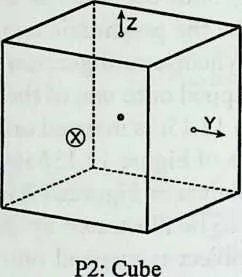
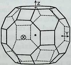
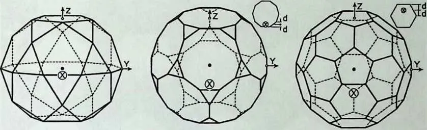
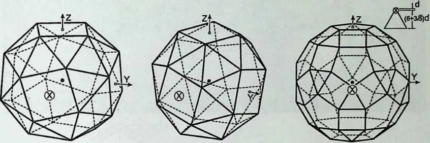
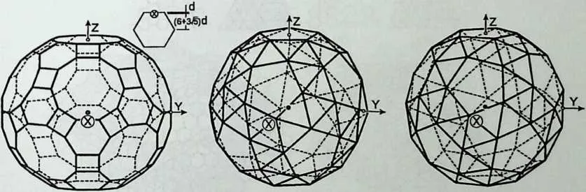
174The standard coordinate system for the tetrahedron is shown again in Figure 12.13 together with the standard coordinate systems for all the other Platonic and Archimedean polyhedra. Some of the polyhedra in this figure have additional sketches shown near them. The tetrahedron, for example, has such a sketch. These sketches provide information about the precise positions of the X-points and are included whenever the positions of the X-points are not obvious from the main figures.
175 A view of a set of cardboard models of Platonic and Archimedean polyhe-
176 TABLE 12.1 Properties of Platonic and Archimedean Polyhedra
|
180Polyhedron |
181Faces, 182Edges, Vertices |
183Radius of Insphere |
184Radius of Intersphere |
185Radius of Circumsphere |
186Dihedral Angle |
|
187Pl: Tetrahedron |
188F3:4 189E: 6 190V:4 |
19112 (0.204124145 Z) |
1924 (0.353553390 Z) |
195/ 1 X acos(y) (70.5287794°) |
|
|
196P2: Cube |
197F4: 6 198E: 12 199V: 8 |
200L 2 |
201Z 202■Ji (0.707106781 Z) |
203—Z 2 (0.866025403 Z) |
20490° |
|
205P3: Octahedron |
206F3: 8 207E: 12 208V: 6 |
209_L_ 210JU 211(0.408248290 L) |
212L 2 |
213Z 214■Ji (0.707106781 Z) |
215/-lx acos(—) 216(109.471221°) |
|
217P4: Dodecahedron |
218F5: 12 219E: 30 220V: 20 |
221725+1175 2710 (1.11351636 Z) |
2223 + 75 T la 4 (1.30901699 Z) |
226acos(-) (116.565051°) |
|
|
227P5: Icosahedron |
228F3:20 229E: 30 230V: 12 |
2313+ 473 (0.755761314 Z) |
232l + 75z 4 (0.809016994 Z) |
237/-75 k acos(—) (138.189685°) |
|
|
238P6: Truncated 239Tetrahedron |
240F3:4 F6:4 E: 18 V: 12 |
241Z 4 (0.612372435 Z) |
242372 _ 4 (1.06066017 Z) |
243722z 4 (1.17260394 Z) |
244[6–6] acos( 1/3) 245(70.5287794°) 246[6–3] acos(-l/3) (109.471221°) |
|
247P7: Cuboctahedron |
248F3: 8 249F4: 6 250E:24 251V: 12 |
252L 253■Ji (0.707106781 Z) |
256Z |
257acos(-y) (125.264390°) |
|
|
258PS: Truncated Cube |
259F3: 8 F8: 6 E: 36 260V:24 |
261l+£ 2 (1.20710678 Z) |
2622+-J2 r 263—JL 2642 265(1.70710678 Z) |
26677 + 472 T la 2672 268(1.77882365 Z) |
269[8–8] 90° 270[8–3] acos(-1/5/3) 271(125.264390°) |
|
272P9: Truncated Octahedron |
273F4: 6 274F6: 8 275E: 36 276V: 24 |
277Z 2 (1.22474487 Z) |
2783-l 2 |
279TiOz 2 (1.58113883 Z) |
280[6–6] acos(-l/3) 281(109.471221°) 282[6–4] acos(-1/5/3) 283(125.264390°) |
|
287F3: 8 288F4: 18 289E: 48 290V: 24 |
291i+z 2 (1.20710678 Z) |
292J1 + 2-J2 r 293…. ■ 2z 2942 295(1.30656297 Z) |
299[4–4] 135° 300[4–3] acos(-5/6/3) 301(144.735610°) |
||
|
302PH: Great Rhombicub-octahedron |
303F4: 12 304F6: 8 305F8: 6 306E: 72 307V: 48 |
3081+2–72 r jlz 2 (1.91421356 Z) |
309J12 + &J2 r ' la 2 (2.26303344 Z) |
313[8–6] acos(-l/x/J) 314(125.264390°) 315[8–4] 135° 316[6–4] acos(-5/6/3) 317(144.735610°) |
|
|
318Pll: Icosido-decahedron |
319F3: 20 320F5: 12 321E: 60 322V: 30 |
323J5+245 t ■Js (1.37638192 Z) |
32475+2–75 T 2 (1.53884177 Z) |
3251 + 5Z 2 (1.61803399 Z) |
|
|
329P13: Truncated 330Dodecahedron |
331F3: 20 332F10:12 333E: 90 334V: 60 |
335J50 + 22J5 T la 4 (2.48989829 Z) |
342[10–10] acos(-1/5/5) (116.565051°) 343[10–3] acos( ) 344(142.622632°) |
||
351 TABLE 12.1 Properties of Platonic and Archimedean Polyhedra (continued)
|
355Polyhedron |
356Faces, Edges, Vertices |
357Radius of Insphere |
358Radius of Intersphere |
359Radius of Circumsphere |
360Dihedral Angle |
|
3623=F5: 12 363F6: 20 364E: 90 365V: 60 |
369[6–6] acos(-75/3) |
||||
|
3702=P14: Truncated 371Icosahedron |
3732=742 + 1875 4 (2.26728394 Z) |
3743 + 3£ |
375758+1875 r |
376(138.189685°) |
|
|
3804 (2.42705098 Z) |
383rrcl (-75+275 \ 384[6–5] acos( ) 385(142.622632°) |
||||
|
3872=F3:32 388F4: 6 389E: 60 390V: 24 |
|||||
|
395P15: Left Snub 396Cube 397P16: Right Snub |
399Z 2k (1.14261351 Z) |
40071 +A:2 T 4012k (1.24722317 Z) |
40271 + 2A:2 T 4032k (1.34371337 Z) |
404[4–3] 142.983430° 405[3–3] 153.234588° |
|
|
406Cube |
k
is
equal
to
0.437593286
and
represents
the
ratio
of
the
edge
length
of
a
snub
cube
and
that
of
its
parent
cube.
The
angle
of
rotation
of
a
square
face
of
a
snub
cube
with
respect
to
the
corresponding
face
of
its
parent
cube
is
equal
to
16.4675604°.
| ||||
|
4082=F3: 20 409F4: 30 410F5: 12 411E: 120 412V: 60 |
4162=(-710 + 275 \ [5–4] acos —7= 417v 275 ' 418(148.282526°) 419[4–3] acos( (-}) 420(159.094843°) |
||||
|
42535 + 275 426275 (2.06457288 Z) |
427710 + 475 T ■1 ■‘‘ 4282 429(2.17625090 Z) |
430711 + 475 2 431(2.23295051 Z) |
|||
|
4332=F4: 30 434F6: 20 435F10:12 436E: 180 437V: 120 |
441/ —5/5+2 V5 \ 442[10–6]acos( ) 443(142.622632°) |
||||
|
444P18: Great Rhombicosi-dodecahedron |
446725 + 105 r 4472 (3.44095480 Z) |
448730+1275 r 4492 (3.76937713 Z) |
450731+1275 T 451■‘‘Jj 4522 453(3.80239450 Z) |
454(-710 + 275 1 455[10–4] acos( ) 456(148.282526°) 457[6–4] acos(z<l±)) 458(159.094843°) |
|
|
465P19: Left Snub 466Dodecahedron 467P20: Right Snub |
468F3: 80 469F5: 12 470E: 150 471V: 60 |
472125 + 1175 473V 40£2 (1.98091595 Z) |
4741 3 + V5+2k2 L V (40–1675) k2 475(2.09705384 Z) |
476l7 + 3V5 + 8k2J. \(20–4j5)k2 477(2.15583737 Z) |
478[5–3] 152.929920° 479[3–3] 164.175366° |
|
480Dodecahedron |
k
is
equal
to
0.562121965
and
represents
the
ratio
of
the
edge
length
of
a
snub
dodecahedron
and
that
of
its
parent
dodecahedron.
The
angle
of
rotation
of
a
pentagonal
face
of
a
snub
dodecahedron
with
respect
to
the
corresponding
face
of
its
parent
dodecahedron
is
equal
to
13.1064034°.
| ||||
488489Some General Relations
490 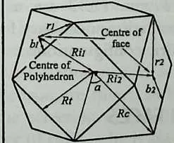 (l)Rc=7/?t2+Z2/4 (2)Ri=Rc2-L2/4 Q)Rip=Rc2 -rp2 (4) Rip = yj R12 -bp2 (5) L =
2'Jrc2-Ri2 (6) a - 2 asin(Z/2Rc) (7) a = 2 acos(A//7?c) (8) a = 2 atan(Z/2Rt) The above
relations are applicable to every Platonic and Archimedean polyhedron, where: ■ Z is the
edge length ■ a is the angle subtended by an edge at the center of the polyhedron ■
Rc is the radius of the circumsphere ■ Rt is the radius of the intersphere ■ Rip is
the radius of an insphere, that is, a sphere which is tangent to all the faces of type p
■ rp is the distance between the center and a comer of a face of type p ■ bp is the
distance between the center and the midpoint of a side of a face of type p ■ The radius
of insphere for an Archimedean polyhedron given in the third column of the table
corresponds to the smallest insphere, that is, the insphere which is tangent to the largest
faces.
(l)Rc=7/?t2+Z2/4 (2)Ri=Rc2-L2/4 Q)Rip=Rc2 -rp2 (4) Rip = yj R12 -bp2 (5) L =
2'Jrc2-Ri2 (6) a - 2 asin(Z/2Rc) (7) a = 2 acos(A//7?c) (8) a = 2 atan(Z/2Rt) The above
relations are applicable to every Platonic and Archimedean polyhedron, where: ■ Z is the
edge length ■ a is the angle subtended by an edge at the center of the polyhedron ■
Rc is the radius of the circumsphere ■ Rt is the radius of the intersphere ■ Rip is
the radius of an insphere, that is, a sphere which is tangent to all the faces of type p
■ rp is the distance between the center and a comer of a face of type p ■ bp is the
distance between the center and the midpoint of a side of a face of type p ■ The radius
of insphere for an Archimedean polyhedron given in the third column of the table
corresponds to the smallest insphere, that is, the insphere which is tangent to the largest
faces.
492 (a) (b)
493 Figure 12.12 A coordinate system for tetrahedron.
494 dra is shown in Figure 12.14. The models of the Platonic polyhedra are placed in the front row and those of the Archimedean polyhedra are arranged in the three back rows. The X-point and Z-point for each model are situated at the centers of the circular spots on the model. The darker spot that appears in front of the model indicates the position of the X-point and the lighter spot that appears on the top indicates the position of the Z-point.
495 From the point of view of compatibility of the coordinate systems, as given in Figure 12.13, the Platonic and Archimedean polyhedra may be divided into three groups. First, there is a group consisting of two polyhedra, namely, the tetrahedron and truncated tetrahedron. These two polyhedra occupy the central part of the family tree in Figure 12.10. The coordinate systems for these polyhedra are compatible with each other. By the term compatible, in this context, it is meant that when a truncated tetrahedron is produced by cutting off the comers of a tetrahedron, then the original coordinate system of the tetrahedron will become the coordinate system for the truncated tetrahedron without any change.
496 The second family of polyhedra with compatible coordinate systems consists of nine polyhedra. These are the polyhedra that can be derived from the cube or octahedron and appear to the left of the center in the family tree of Figure 12.10. The third family of polyhedra with compatible coordinate systems again has nine members. These are the polyhedra that can be derived from the dodecahedron or icosahedron and appear to the right of the center in the family tree of Figure 12.10.
497 The standard coordinate systems shown in Figure 12.13 are used in Formian as the basis for formulation of the transformations necessary for the creation of numerical models representing polyhedric configurations.
498 IDENTITY NUMBERS AND BASELINES FOR FACES OF POLYHEDRA
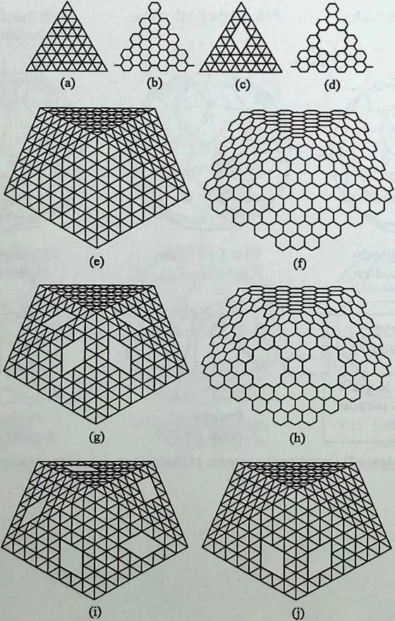
499 Figure 12.15e shows a polyhedric configuration that is obtained by mapping the face-object of Figure 12.15a onto the top five faces of an icosahedron. If the face-object for mapping onto the faces is chosen to be that of Figure 12.15b, then the result will be the polyhedric configuration shown in Figure 12.15/ In the case of the polyhedric configuration of Figure 12.15g, the faceobject of Figure 12.15/7 is mapped onto one of the top faces of an icosahedron and the face-object of Figure 12.15c is mapped onto the remaining four faces. The polyhedric configuration of Figure 12.15b is obtained by a similar procedure using the face-objects shown in Figures 12.15b and d.
500 The point that is meant to be illustrated by the above examples is that in most practical cases a face-object is mapped onto a selected number of the faces rather than all the faces of a polyhedron. In the examples of Figures 12.15 e-h, the top five faces of an icosahedron have been selected for mapping. Furthermore, in the examples of Figures 12.15g and b, one of the faces has been selected for mapping of a face-object and the other four faces have been selected for mapping of a different face-object. In order to select faces, it is necessary to have a means of identifying the faces of a polyhedron. This is achieved by associating an identity number with each face of a polyhedron, as will be described later.
501 Another problem that has to be addressed is illustrated in terms of the polyhedric configurations shown in Figures 12.15/ and/. Figure 12.15/ shows a polyhedric configuration that is obtained by mapping the face-object of Figure 12.15c onto the top five faces of an icosahedron. However, the orientation of the face-object as mapped onto the faces in Figure 12.15/ is different from the orientation of the face-object as it appears in Figure 12.15c. The polyhedric configuration shown in Figure 12.15/ has the face-object of Figure 12.15/7 mapped onto three of the faces and the face-object of Figure 12.15c mapped onto two of the faces with different orientations. These examples show that, in addition to the requirement of an identity number for each face of a polyhedron, it is also necessary to associate a frame of reference with the face. This would then allow the required position of a face-object for mapping onto the face to be specified unambiguously.
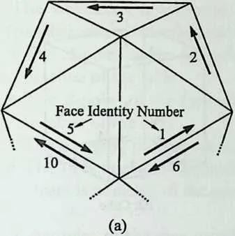
502 A frame of reference for a face of a polyhedron is established by assigning the status of baseline to one of the sides of the face and by associating the letters A and B to the end points of this baseline, as shown in Figures 12.16a and b. The end of the baseline that is associated with the letter A is referred to as the 4-end and the end that is associated with the letter B is referred to as the 2?-end. The baseline of a face is indicated by a vector. The vector is placed near the baseline with its arrowhead showing the direction from the A-end to the 5-end. In addition, the identity number of each face is placed near the baseline vector.
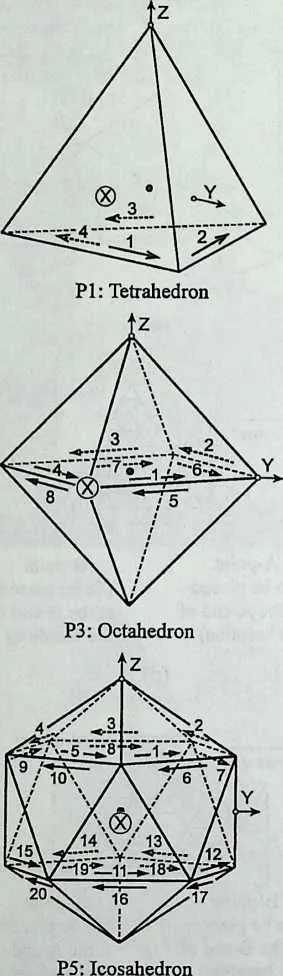
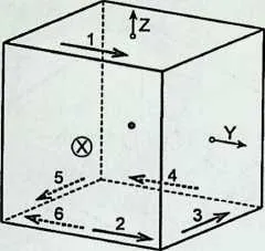
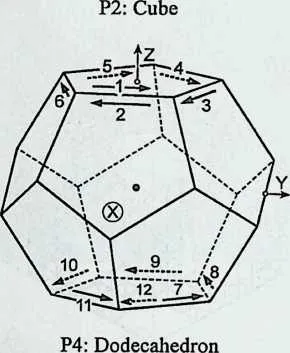
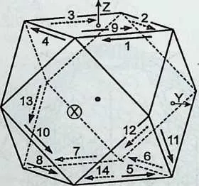
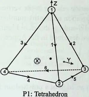
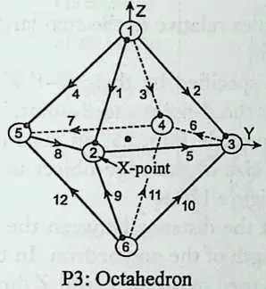
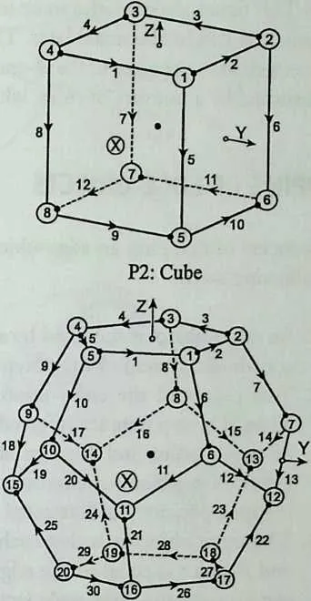
503 The baseline vectors and the face identity numbers for the top part of an icosahedron are shown in Figure 12.16a. The allocation of identity numbers and the selection of baselines for the faces of polyhedra are governed by a number of rules, which are described in the Appendix. Also, the face identity numbers together with the baselines for a group of six polyhedra are shown in Figure 12.17. This group contains all the Platonic polyhedra and one Archimedean polyhedron, namely, the cuboctahedron.
505 P4: Dodecahedron
506 P5:Icosahedron
507 P6: Truncated
508 Tetrahedron
509 P8: Truncated Cube
510 P9: Truncated
511 Octahedron
512 PIO: Small Rhombi-cuboctahedron
513 Pl 1: Great Rhombi-cuboctahedron
514 Figure 12.13 (part 1) Coordinate systems of Platonic and Archimedean polyhedra.
516 P12: Icosido-Pl3: Truncated Pl4: Truncated
517 decahedron Dodecahedron Icosahedron
518 Pl5: Left Snub Cube
519 Pl6: Right Snub Cube
520 Pl7: Small Rhomb-
521 icosidodecahedron
523 Pl8: Great Rhomb-icosidodecahedron
524 Pl9: Left Snub Dodecahedron
525 P20: Right Snub Dodecahedron
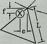
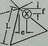
526 e is parallel to the Y
527 axis and f is parallel to the Z axis.
528 e = 0.192893711 L f= 0.144866867 L
529 Position of X-pointforP19
530 Position of X-point for P20
532 Figure 12.13 (part 2) Coordinate systems of Platonic and Archimedean polyhedra.
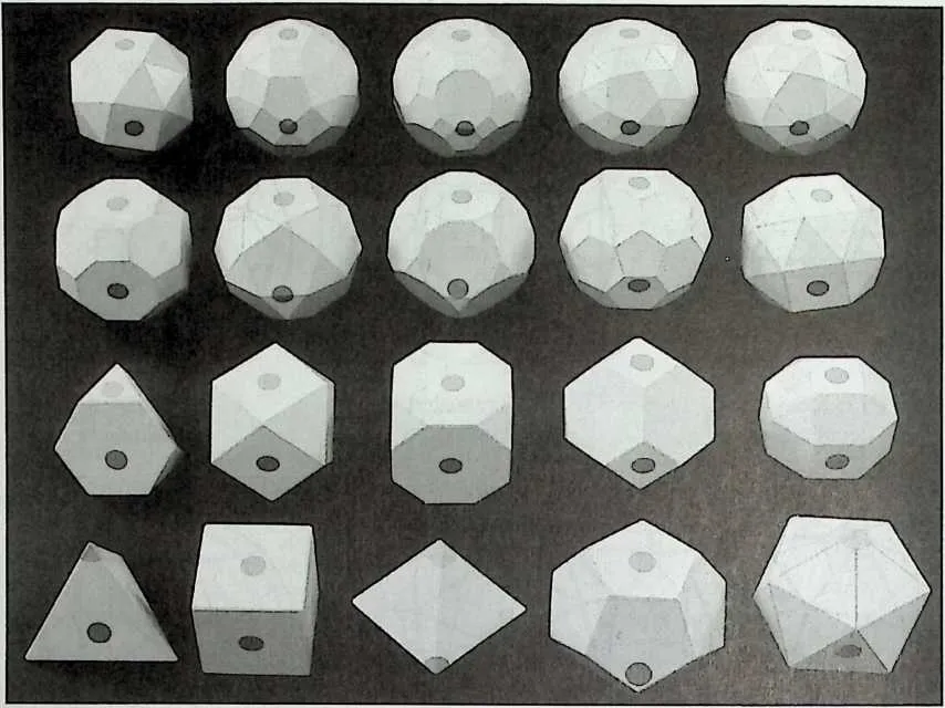
534 Figure 12.14 Models of Platonic and Archimedean polyhedra with the darker front spots indicating the X-points and the lighter top spots indicating the Z-points.
536 Figure 12.15 Examples of face mapping.
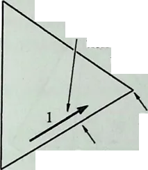
538 B-end
539 Baseline
540 A-end
541 (b)
542 Vector indicating the baseline
of face No 1 with the arrow-
head showing the direc-
tion from the A-end
to B-end

544 Z (upward)
545 WaTaWaV HtatatatA HtatataTaTO—.Atatatatatat ▼atatatatatjM »rAVAVJ«rAVAW Wava /avaVa VAVAVA_yAVAVA7/
546 Face-object
547 A-point (To be placed at the A-end of the baseline)
548 B-point (To be placed at the B-end of the baseline)
549 (d)

551 Z (upward)
552 VatatataI
553 KotaTaTO_
554 .JATATATATATATAW fcrAVATATATATA ▼AlVMWrATj
555 WaVaVaX MW
556 IAVAVASkTAVA F. VaVavavavavav/
557 Face-object
558 B-point (To be placed at the B-end of the baseline)
559 A-point (To be placed at the A-end of the baseline)
561562
(f)
563 Figure 12.16 Face-mapping process.
564 MAPPING OF FACE-OBJECTS
565 The process of mapping a face-object onto a face of a polyhedron involves the following steps:
- 1.
- A face-object is specified by a formex relative to the standard X-Y-Z coordinate system of the polyhedron.
- 2.
- Two points of the face-object are specified by their X-Y-Z coordinates. These points are referred to as the A -point and B-point. The role of the /(-point and B-point is to provide information regarding the required
568 Figure 12.17 Identity numbers and baselines for the faces of a selection of polyhedra.
570571position, orientation, and size of the face-object in its final mapped position on the face of the polyhedron, as exemplified in Figures 12.16c-f.
- 3.
- The face-object is scaled such that the distance between the A-point and 5-point is equal to the edge length of the polyhedron. In this scaling process, the same scale factor is used in the X, Y, and Z directions.
- 4.
- The mapping plane is determined. This is the plane of the face-object that is to coincide with the face of the polyhedron. If the line containing the A-point and B-point of the face-object is parallel to (or coincident with) the X axis, then the mapping plane is the plane that contains the A-point and 5-point and is parallel to (or coincident with) the X-Y plane. This simple case is applicable in most practical situations and is the only case considered here.
- 5.
- The face-object is subjected to a sequence of rigid-body movements (translations and rotations) such that the following conditions are satisfied:
- The //-point of the face-object is coincident with the ?/-end of the baseline of the face.
- The B-point of the face-object is coincident with the B-end of the baseline of the face.
- The mapping plane is coincident with the face.
574575° The direction that was initially the positive Z direction of the faceobject is pointing to the outside of the polyhedron.
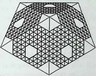
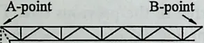
576 Two examples of the face-mapping process are shown in Figure 12.16. Figure 12.16c shows the top part of an icosahedron with a face-object mapped onto five faces. The boundaries of these faces are shown by dotted lines. The face-object is shown in Figure 12.16d with the line that passes through the-point and B-point being parallel to the X axis. The mapping is achieved by suitably scaling the face-object and then placing it on each face in a position where the /(-point coincides with the /(-end of the basefine of the face and the B-point coincides with the B-end of the baseline of the face.
577 It is important to note that the //-point and B-point of the face-object need not necessarily be actual points of the face-object. For example, in the case of the face-object in Figure 12.16d, the //-point and B-point are outside the face-object altogether. The dotted lines here are included to indicate the positions of the y4-point and B-point. These dotted lines are not supposed to be part of the face-object.
578 A second example of face mapping is shown in Figures 12.16e and/ The face-object in this example is the same as that of the previous one. The only difference is in the positions of the //-point and B-point. To be specific, the positions of the /(-point and B-point have crossed over as well as being shifted. Consequently, the face-object has been turned around for mapping.
579 IDENTITY NUMBERS AND DIRECTIONS FOR EDGES OF POLYHEDRA
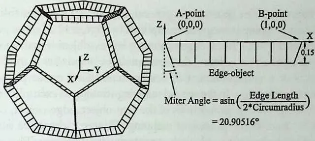
580 The upper part of Figure 12.18/z shows a polyhedric configuration that is obtained by mapping a truss configuration on the edges of an octahedron. The edge-object is shown in the lower part of Figure 12.18a with the //-point and B-point being assumed to be on the X axis. The mapping is carried out by placing a suitably scaled version of the edge-object on the edges of the octahedron. For each edge, the edge-object is positioned such that the end points of the top chord of the truss coincide with the end points of the edge and the plane of the truss passes through the center of the octahedron. The angle of the inclined sides of the truss is chosen such that, after mapping on the edges of the octahedron, the ends of the bottom chords of the trusses meet without any gaps. The term miter angle is used to refer to the angle that will allow the ends of the trusses to match after mapping. Figure 12.18b shows the result of
581 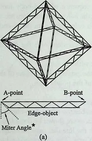
 where L is the edge length of the polyhedron and Rc is the radius of its
circumsphere.
where L is the edge length of the polyhedron and Rc is the radius of its
circumsphere.
582 * The ‘mitre angle’ is given by: asin(L/2Rc)
583 Edge-object
584 Miter Angle
585 (c)
586 Figure 12.18 Examples of edge mapping.
587 mapping a Vierendeel-girder-type configuration on the edges of a dodecahedron. Also, the result of mapping a truss-like configuration on the upper half of a cuboctahedron is shown in Figure 12.18c.
588 If the edge-object consists of a plane configuration and if this is to be mapped on the edges of a Platonic or Archimedean polyhedron, then the miter angle may be obtained from the general formula given at the right bottom corner of Figure 12.18.
589 In order to carry out the mapping of an object on an edge of a polyhedron, it is necessary to identify the edge on which the object is to be mapped and to estabfish a way of specifying the position, orientation, and size of the object at its final mapped form. The identification of the edges of a polyhedron is achieved by allocating an identity number to each edge, as exemplified in Figure 12.18d for the upper half of a cuboctahedron. Also, each end of an edge is
591 P4: Dodecahedron
592 P5:Icosahedron
593 Figure 12.19 Identity numbers, directions, and handles for edges and vertices of a selection of polyhedra.
594 P7: Cuboctahedron
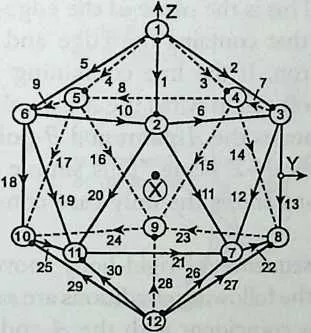
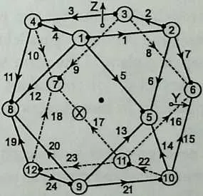
595 associated with a letter. One end is associated with the letter A and is referred to as the /4-end and the other end is associated with the letter B and is referred to as the 5-end. The /Tends and 5-ends for two of the edges of a cuboctahedron are shown in Figure 12.18d. The convention is adopted that the positions of the /Tend and 5-end of an edge are indicated by placing an arrowhead on the edge pointing from the /Tend to the 2?-end, as shown in Figure 12.18*7. Thus the /Tend and 5-end effectively establish a ‘‘direction’’ for the edge.
596 The identity numbers of the edges together with the arrowheads indicating the /Tends and 5-ends for the Platonic polyhedra and a sample of an Archimedean polyhedron (namely, a cuboctahedron) are shown in Figure 12.19. This figure also includes some information relating to the vertices of the polyhedra, as will be discussed later. The allocation of identity numbers to the edges as well as the choices of the/(-ends and 5-ends, as shown in Figure 12.19, are governed by a number of rules, which are described in the Appendix.
597 MAPPING OF EDGE-OBJECTS
598 The process of mapping an edge-object on an edge of a polyhedron involves the following steps:
- 1.
- An edge-object is specified by a formex relative to the standard X-Y-Z coordinate system of the polyhedron.
- 2.
- Two points of the edge-object are specified by their X-Y-Z coordinates. These points are referred to as the A -point and 5-point. The role of the /(-point and 5-point is to provide information regarding the required position, orientation, and size of the edge-object in its final mapped position, as illustrated in Figure 12.18.
- 3.
- The edge-object is scaled such that the distance between the 24-point and 5-point is equal to the edge length of the polyhedron. In this scaling process, the same scale factor is used in the X, Y, and Z directions.
- 4.
- The mapping plane is determined. This is the plane of the edge-object that is to coincide with the plane that contains the edge and passes through the center of the polyhedron. If the fine containing the A- point and B-point is parallel to (or coincident with) the X axis, then the mapping plane is the plane that contains the /(-point and 5-point and is parallel to (or coincident with) the X-Z plane. This simple case is applicable in most practical situations and is the only case considered here.
- 5.
- The edge-object is subjected to a sequence of rigid-body movements (translations and rotations) such that the following conditions are satisfied:
- The /(-point of the edge-object is coincident with the /(-end of the edge.
- The 5-point of the edge-object is coincident with the 5-end of the edge.
- The mapping plane is coincident with the plane that contains the edge and passes through the center of the polyhedron.
- The direction that was initially the positive Z direction of the edgeobject is pointing to the outside of the polyhedron.
600 IDENTITY NUMBERS AND HANDLES FOR VERTICES
601 OF POLYHEDRA
602 Examples of mapping of objects on the vertices of polyhedra are shown in Figure 12.20. lb begin with, as for the faces and edges, it is necessary to allocate an identity number and a frame of reference to each vertex of a polyhedron.
604 B-point -—(To be placed at the B-end of the handle)
605 Vertex-object
606 A-point (To be placed at the A-end of the handle)
607 (b)
608 Vertex-object
609 (To be placed at the B-end of the handle)
610 A-point (To be placed at the A-end of the handle)
611 (c)
612 Figure 12.20 Examples of vertex mapping.
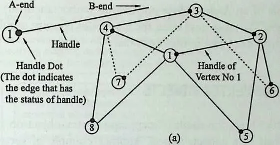
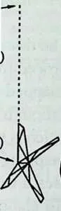
613 Identity numbers for vertices in the upper half of a cuboctahedron are shown in Figure 12.20a. The convention is adopted that a vertex identity number is shown in a circle placed at the vertex. The frame of reference for a vertex is provided by selecting one of its edges to become a base with respect to which vertex-objects may be mapped on the vertex. This edge is referred to as the handle of the vertex. Also, the vertex end of the handle is referred to as the A- end and the other end is referred to as the 5-end. The convention is adopted that the handle of a vertex is indicated by placing a dot (referred to as a handle dot) at its Af-end, as shown in Figure 12.20#.
614 The vertex identity numbers and handles for all the Platonic polyhedra and a sample of an Archimedean polyhedron (cuboctahedron) are shown in Figure 12.19. The rules governing the choices of identity numbers and handles for vertices are given in the Appendix.
615 MAPPING OF VERTEX-OBJECTS
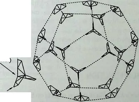
616 Figure 12.20£ shows the result of mapping a vertex-object on the vertices of the upper half of a cuboctahedron. Another example of vertex mapping is shown in Figure 12.20c, where a vertex-object is mapped on the vertices of a dodecahedron.
617 With one important difference, which will be discussed below, the process of mapping a vertex-object is identical to the procedure for mapping an edgeobject. To elaborate, if a vertex-object is to be mapped on a vertex of a polyhedron, then the procedure followed will be as though the vertex-object is an edge-object that is to be mapped on the edge which is the handle of the vertex.
618 The important difference between vertex mapping as compared with edge mapping (and face mapping) is that, in some cases, a vertex-object is to be subjected to reflection in the mapping process. To elaborate, the mapping of a face-object or an edge-object is always carried out through a sequence of rigid-body movements (translations and rotations) and simple scaling. This fact remains true for a vertex-object in most cases. However, for two Archimedean polyhedra the process of mapping a vertex-object may require an additional operation of reflection. These two polyhedra are Pll (great rhombicuboctahedron) and P18 (great rhombicosidodecahedron) and the reason for the need for reflection in these cases is discussed in the Appendix.
619 POLYMATION FUNCTION
620 The processes involved in mapping objects on the faces, edges, and vertices of polyhedra are discussed in the previous sections. In Formian, these processes are carried out through the polymation function. For example, a Formian instruction that creates a formex representing the polyhedric configuration of Figure 12.20c may be written as
621 G = pol(3, 4, '[all]', 1, [0,0; 1,01)1 E
622 where
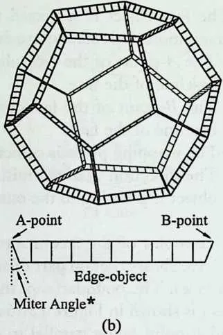
- E is a formex representing the vertex-object.
- G is a formex representing the polyhedric configuration of Figure 12.20c.
- pol is an abbreviation for the name of the function, that is, polymation.
- The first item in parentheses is the operation code specifying the type of mapping to be performed, where the integer 3 indicates mapping on vertices.
- The second item in parentheses is the polyhedron code specifying the
'Operation code' specifies the type of operation to be performed, namely, mapping on faces, mapping on edges or mapping on vertices. The operation code is an integer expression whose value is 1, 2 or 3 specifying mapping on faces, edges or vertices, respectively. In the example shown, the integer 2 specifies mapping on edges.
624625'Polyhedron code' specifies the type of polyhedron to be used as the basis for the operation. The polyhedron code is an integer expression whose value is in the range 1 to 20 specifying one of the Platonic or Archimedean polyhedra. In the example shown, the integer 7 indicates cuboctahedron.
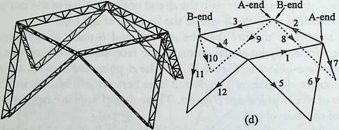
626'Radius specifier1 determines the size of the polyhedron by specifying the radius of its circumsphere. The radius specifier is a numeric expression whose value is a nonzero positive number. In the example shown, the radius is given as 10. It is possible to specify different radii for different layers of the object to be used for mapping. In this case, the radii are specified in terms of a formex expression.
627 T
629630'Entity list' gives the list of face, edge or vertex numbers on which mapping is to be performed. The entity list is a string expression whose value is a list of items separated by commas. The items in the example shown are 1–7, 11 and 12, where 1–7 is equivalent to 1, 2, 3,4, 5, 6 and 7. It is possible to use 'all' as an item implying all the faces, edges or vertices, as appropriate, listed in the ascending order. An item may also be a negative integer, like -8, or a negative parenthesised list, like -(6,12–15,9). A negative item has a cancelling effect
631'Locator1 is a formex expression whose value specifies the coordinates of the A-point and B-point of the object to be used for mapping. In the example shown, 0,0 and 1,0 are the coordinates of the A-point and B-point of the object respectively.
632 Figure 1221 Polymation function.
633 polyhedron to be used as the basis for mapping. The polyhedron code is the integer that follows the letter P in the P-name of a polyhedron. The integer 4 in the example implies a dodecahedron.
634 The third item in parentheses is the entity list specifying the vertices on which mapping is to be performed. The entity list as given in the example indicates all the vertices.
635 The fourth item in parentheses is the radius specifier, which determines the size of the polyhedron by specifying the radius of the circumsphere of the polyhedron.
636 The last item in parentheses is the locator specifying the yl-point and B- point of the vertex-object. In general, the /{-point and 5-point are to be specified by giving their X, Y, and Z coordinates. However, if the third coordinates are not given, then it will be assumed that the Z coordinates are equal to 0. In the example, the X and Y coordinates of the /4-point are given as 0,0 and those of the B-point are given as 1,0. The Z coordinates will then be assumed to be equal to 0.
637 The items within parentheses provide information about the manner in which the mapping is required to be carried out. Further details about these items are given in Figure 12.21. Information about the locations of all the faces, edges, and vertices of Platonic and Archimedean polyhedra, in terms of their identity numbers, is incorporated into Formian. This information is used by the polymation function for determining the locations of the faces, edges, or vertices specified by the entity list (third item in parentheses in Figure 12.21). Also, Formian incorporates complete information about the baselines of faces, directions of edges, and handles of vertices for the Platonic and Archimedean polyhedra. This information is used by the polymation function for the correct positioning of the objects to be mapped.
638 The argument of the polymation function in Figure 12.21 is represented by E and is separated from the function by the symbol I. Normally, this argument is a formex variable that represents the object to be used for mapping. Examples of formex formulations for the creation of formex variables representing the mapping objects are shown in Figure 12.22. Figure 12.22a shows a face-object together with its formex formulation, which is shown in a box. This formex formulation gives rise to a formex variable F that represents the face-object. The face-object has a pattern similar to the one used for the poly-
639 AvavA
AvavavA
AvavavavA
/avavaVaVavA
/AVaVaVaVaVaVA
AvaTaVaVaVaVavA
/AvavavavaVavavavaX ‘
/WAVaVVaVaVaVA'*
AvaVavaVaWaVaVaVavA
AvaVaVAVZVVaVaVaVaS’-'
. AvaVaVaVaVALJaVaVaVavA .
. AvavaVav/-w/vyataW3
640 AvavavavaWaWaWaVaVaVavA I
641 ' AvaVavaVaVAavAWavayavavJMM
/A'AVaVAVAVaVaVaVaVaVAVAVaVaVaVaVaVA
AvaVaVAVaVaVaVaVaVaVaVaVaVaVaVaVaVavA
642 F=bb(l,sqrt 13) | lux(genid(4,M,2,2,-l) | [15,5]) | genid(21,21,2,1,1,-!) | {[0,0;2,0],[2,0;l,l],[l,l;0,0]}
643 (a)
644 E=pan(2,0) | (rin(l,20,l) | [0,0;l,0]#rin(l,10,2) | lam(l,l) | [0,0;l,-2]#rin(l,18,l) | [l,-2;2z-2]#rin(l,19,l) | [l,0;l,-2]) s /
645 (b)

648649a=-0.15; b=0.25; c=-a*tan | asin | (0.5/1.40125854) 'V=iosax(0,0,0:,0,a,'12D) | {[0,0,0;b,0,0],[0,0,0;c,0,a],[c,0,a;
650 Figure 12.22 Formex formulations for a face-object, an edge-object, and a vertex-object.
652653b,0,a/2],[c,0,a;b/2,0,0j,[b/2,0,0;b,0,a/2],[b,0,0;b,0,a/2])
654 (c)
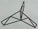
655 hedric configuration of Figure 12.3zz. A truss-like edge-object together with its formex formulation is shown in Figure 12.22k Also, a vertex-object with its formex formulation is shown in Figure 12.22r. This is the vertex-object used for the polyhedric configuration of Figure 12.20c.
656 A reader who is familiar with the concepts of formex algebra will be able to follow the formex formulations of Figure 12.22. However, a reader who is unfamiliar with formex algebra should not worry about the details of the formulations at this point. In the present discussion the main aim is to describe the basics of the processes that are involved in the creation of polyhedric configurations. The formex formulations in this context may then be seen as ‘‘boxes of instructions’’ that imply the given configurations.
657 SHAPING AND COMPOSING POLYHEDRA
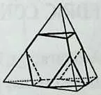
658 The polymation function may be employed to create a variety of different kinds of polyhedric configurations, some of which are outside the categories of configurations discussed so far. Two such classes of polyhedric configurations are discussed next.
659 The configurations shown in Figure 12.23 are obtained by cutting away
661 G=pex | pol(l,l,'[all]',l,[0A0;l,0,0]) | rosad(l/2,sqrt 13/6,
662 3,120) | {[0.4,0,0;0.6,0,0],[0.4,0,0;0.2,sqrt 13/5,0])
664665GoKl/faUJMJO.OAlAOJJIAOltfpol/ig-lMlO,)]', l,[0,0,0;l,0,0D | dil(3,05) | tranix(05,0.5,0.5) | poipA'11–8]’, sqrt 13/2,[0,0,0;!,0,0]) | [0,0,0;l,0,0]
667 G=pol(l,2,'[l]',l,[0,0,0;2,0,0]) | rosad(l,l) | [0,l,0;l,0,0]#rosad(0,0) |
pol(l,2,'[2]',l,[0,0,0;2,0,0]) |{[0,0,0;2,0,0],[2,0,0;1,2,0],[1,2,0;0,0,0]}
k. /
669670(b)
672 G=rosad(0,0) | pex | lam(3,0) | pol(lA'[ir/l,[0,0,0;4,0,0]) |
{[0,0,0;4,0,0],[0,0,0;l,tan 160,0],[l,tan 160,05, tan 160,0]}
674 G=pol(25,'[aU]',1/sqrt 12,[0,0,0;l,0,0]) | [0,0,0;l,0,0]#pol(l ,3,,[1,7]', 1/sqrt 12,[0,0,0;l,0,0]) | ver(2,1,0,0) | tranix(-cos 130/3,0.5, 1/sqrt 124) | pol(2,l,'[l-3]',sqrt 16/4,[0,0,0;l,0,0J) | [0,0,0;l,0,0]
676 G=pex | lam(3xos | (2*asin | (05/0.951056516))) |
pol(25,'[l-10]',l,[0,0,0;l,0,0]) | [0,0,0;1,0,0]
677 (c)
678 (c)
679 Figure 12.23 Examples of polyhedron shaping.
680 Figure 12.24 Examples of polyhedral compositions.
681 parts of three polyhedra, where the original polyhedra are shown by thin lines and the resulting configurations are shown by thick lines. All three configurations are obtained using the polymation function and the formex formulation for each case is given enclosed in a box.
682 The configuration shown by thick lines in Figure 12.23# is similar to a P6 (truncated tetrahedron), but its proportions are different from those of a P6. The configuration shown by thick lines in Figure 12.23£ is a decahedron (a polyhedron with 10 faces), which is obtained by cutting away parts of a cube, and the configuration shown in Figure 12.23c is again a decahedron, which is obtained by cutting away the top and bottom corners of an octahedron.
683 Examples of another class of polyhedric configuration are shown in Figure 12.24. Here, the polymation function has been used to create polyhedric configurations involving a combination of polyhedra or their parts. The formex formulations for these configurations are shown enclosed in boxes.
684 Figure 12.24/z shows a configuration that is obtained by placing half-cubes on four faces of a cuboctahedron. Figure 12.24Z* shows a configuration that is obtained by placing two tetrahedra on two opposite faces of an octahedron. Figure 12.24c shows a configuration that is obtained by taking the top part of an icosahedron and combining it with its own reflection.
685 PROCESSING OF MULTILAYER POLYHEDRIC CONFIGURATIONS
686 An example of a double-layer polyhedric configuration is shown in Figure 12.25#. Here, a Vierendeel-girder-type edge-object is mapped on a number of edges of a dodecahedron and a formex formulation for the operation is shown enclosed in a box. The approach employed in handling the process is the same as that described for the example of Figure 12.18A
687 Figure 12.25b shows a different approach in dealing with the problem. Here, the mapping of both the top layer and bottom layer of the edge-object is controlled by the polymation function. Thus there are two /l-points and two B-points with additional fourth coordinates for layer identification. A formex formulation for the operation is shown in a box in Figure 12.25 b. Also, the setup of the polymation function for the problem is given in Figure 12.26. The procedure followed in this approach is more elaborate than that used in relation to Figure 12.25#. The main advantage in the second approach is that the problem of mitering is sorted out automatically.
688 The approach employed in creating the polyhedric configuration of Figure 12.25b may also be applied in cases when there are more than two layers and in cases involving multilayer face or vertex mapping.
689 It should be noted that the polyhedric configurations of Figures 12.25# and b are not completely identical. The difference is in the orientations of the web elements. To be specific, the web elements in Figure 12.25# remain perpendicular to the top and bottom chords, whereas the web elements in Figure 12.25b are along radial lines emanating from the center, as indicated by the dotted lines in the figure. However, this particular feature of the configuration of Figure 12.25b should not be considered as a necessary consequence of the second
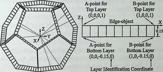
691 rc=1.40125854; a=-0.15; b=l/9; c=-a*tan | asin | (0.5/rc) E=lam(l,0.5) | {[0z0z0;cz0za],[cz0za;bz0za]}#lux([lz0za]) | rin(lz9zb) | {[0z0z0;bz0z0]z[bz0z0;bz0za]z[bz0za;2*bz0za]}
692 G=poI(2z4z'[l-13z-8z18–26z-(23–24)z30]'zrcz[0z0z0;lz0z0]) | E
693 (a)
694 rc=l .40125854; a=-0.15; b=l/9; d=-a/cos | asin | (0.5/rc)
696697E=rin(l,9zb) | [0z0z0zl;bz0z0zl]#rin(lz9zb) | [0z0zaz0;bz0zaz0]#rin(lz10,b) | [0z0z0zl;0z0,az0]
698G=poI(2z4z'[l-13z-8z18–26z-(23–24)z30],z[2z4;lzrc;0zrc-d]z [0z0z0;lz0z0]z[0z0,a;lz0za]) | E
699 (b)
700 Figure 12.25 Double-layer mapping.
701  Number of Layers Operation Code Entity List
702 Polyhedron Code
704705Position of Layer Identification Coordinate
706 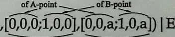 G=pol(2,4,’[1–13,-8,18–26,-(23–24),30]',
707 X-Y-Z Coordinates X-Y-Z Coordinates
708 Locator for
709 Locator for
710 Bottom Layer
711 Radius Specifier
712 [2,4;l,rc;0,rc-d]
714715Value of Layer Identification Coordinate and the
716 Corresponding Circumradius Top Layer
717 Figure 12.26 Polymation function for double-layer mapping. mapping approach. The situation, in general, may be described as follows.
718 In the first mapping strategy, as exemplified by Figure 12.25#, the geometric proportions of the face-object, edge-object, or vertex-object remain unchanged in the process of mapping. Here, the term geometric proportions is used to mean those aspects of a configuration that remain unchanged under photographic enlargement or reduction. In the second mapping strategy, as exemplified by Figure 12.2 Sb, the geometric proportions of the face-object, edge-object, or vertexobject may change in the process of mapping. However, there are no general rules regarding the manner in which the proportions may change. These changes are governed by the choices of the H-points and 5-points.
719 ACKNOWLEDGMENTS
720 The work presented in this chapter has been supported by NASA Grant NAGW-4132 and a grant from the Tomoe Corporation, Japan. Their support is gratefully acknowledged.
12.2 NOTES
- 1.
- H. Nooshin and P. L. Disney, Permian 2, Multi-Science, London, 1997.
- 2.
- J. F. Gabriel, ‘‘Dwelling in Space Structures,’’ in Studies in Space Structures, H. Nooshin, ed., Multi-Science, London, 1991.
- 3.
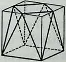
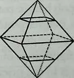
- J. F. Gabriel, ‘‘Space Frames: An Alternative to Architectural Cube,’’ International Journal of Space Structures (Special Issue on the Architecture of Space Frames), Vol. 6, No. 4, 1991.
- 4.
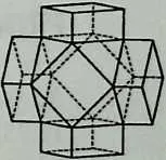
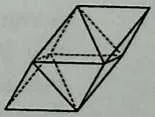
- H. Nooshin and D. Tzourmaldiotou, ‘‘An Approach for Generation of Geodesic Forms,’’ Proceedings of the Fourth International Conference on Space Structures, G. A. R. Parke and C. M. Howard, eds., Thomas Telford, London, 1993.
- 5.
- R. Motro, ‘‘Review of the Development of Geodesic Domes,’’ in Analysis, Design and Construction of Braced Domes, Z. S. Makowski, ed., Granada, London, 1984.
- 6.
- D. L. Richter, ‘‘Developments in Temcor Aluminium Domes,’’ in Analysis, Design and Construction of Braced Domes, V. S. Makowski, ed., Granada, London, 1984.
- 7.
- H. Nooshin, Formex Configuration Processing in Structural Engineering, Elsevier, London, 1984.
- 8.
- A. Pugh, Polyhedra: A Visual Approach, University of California Press, 1976.
- 9.
- H. M. Cundy and A. P. Rollett, Mathematical Models, 2nd ed., Oxford University Press, 1961.
- 10.
- A Gheorghiu and V Dragomir, Geometry of Structural Forms, Elsevier, London, 1978.
723APPENDIX
724 Ordering Rules
725 This appendix contains a collection of rules for ordering the faces, edges, and vertices of a Platonic or Archimedean polyhedron, where the term ordering is
726 used to mean putting in a sequence. The sequencing would then allow identity numbers to be assigned to the faces, edges, and vertices of a polyhedron. This is done by taking the serial position number of an entity in the sequence as its identity number. Included in the appendix are also rules that govern the choices of baselines for faces, /4-ends and E-ends for edges, and handles for vertices. The rules are as follows:
- 1.
- If all the faces of a polyhedron have the same number of sides, then the faces are ordered with respect to the ascending values of the angular spherical coordinates r and t of the centers of the faces, where the value of t is considered first and the value of s is considered only if the centers of the faces compared have the same value of t. The disposition of the r and t spherical coordinates together with the X-Y-Z global coordinate system in relation to a polyhedron (cuboctahedron) is shown in Figure Al2.1.
729730If the faces of a polyhedron have different numbers of sides, then all the faces that have the same number of sides are considered together for ordering, starting with the faces that have the least number of sides and proceeding in the order of increasing number of sides.
- 2.
- For each face of a polyhedron, one of its sides is designated as the baseline. The baseline of a face is chosen in the following manner:
- a.
- If only one of the sides of the face is parallel to the r=90° plane (i.e., the X-Y plane), then this side is chosen as the baseline of the face. The ?=90° plane is referred to as the equatorial plane or the E-plane (Figure A12.1).
- b.
- If only two of the sides of the face are parallel to the E-plane, then, of these two sides, the one that is nearer to the E-plane is chosen as the baseline, and if the sides are equidistant from the E-plane, then the ‘‘southern’’ side is chosen as the baseline.
- c.
- If the face is parallel to the E-plane and one of its sides intersects the r=0° semiplane, then this side is chosen as the baseline of the face. The r=0° semiplane is referred to as the Greenwich plane or the G-
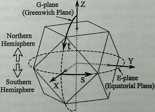
734 Figure A12.1 Cartesian and spherical coordinate systems for a polyhedron.
736737plane. This is the part of the X-Z plane for which X > 0 (Figure A12.1).
- d.
- If the face is parallel to the E-plane and the G-plane passes through a corner of the face, then, of the two sides that are connected to this comer, the one whose midpoint has the smaller r coordinate is chosen as the baseline of the face.
- e.
- If the face does not have a side that is parallel to the E-plane, then the face is imagined to be subjected to a rotation in the ‘‘right-handed screw direction’’ and, as the angle of rotation increases, the first side that assumes a position satisfying either condition (a) or (b) is chosen as the baseline of the face. To describe the term right-handed screw direction, imagine a right-handed screw whose head is at the center of the polyhedron and is pointing toward the center of a face. The direction of rotation that causes the screw to move toward the face is referred to as the right-handed screw direction or the RS-direction.
- 3.
- Each end of the baseline of a face of a polyhedron has an associated letter. To elaborate, one end is associated with the letter A and is referred to as the /Tend and the other end is associated with the letter B and is referred to as the 5-end. The allocation of the letters A and B to the ends is made such that movement from A to B is in the .RS-direction.
- 4.
- The edges of a polyhedron are ordered with respect to the ascending values of the angular spherical coordinates r and t of their midpoints, where the value of t is considered first and the value of r is considered only if the midpoints of the edges compared have the same value of t.
- 5.
- Each end of an edge of a polyhedron has an associated letter. To elaborate, one end is associated with the letter A and is referred to as the A- end and the other end is associated with the letter B and is referred to as the 5-end. The allocation of the letters A and B to the ends is made in the following manner:
- a.
- If the edge is parallel to the E-plane, then the /1-end and 5-end of the edge are chosen such that movement from A to B is in the positive r direction (Figure A12.1).
- b.
- If the edge is not parallel to the E-plane, then the /1-end and 5-end of the edge are chosen such that
- if the midpoint of the edge is in the E-plane or if its midpoint is in the northern hemisphere, then movement from A to B is southward and
- if the midpoint of the edge is in the southern hemisphere, then movement from A to B is northward.
- 6.
- The vertices of a polyhedron are ordered with respect to the ascending values of their angular spherical coordinates r and t, where the value of t is considered first and the value of r is considered only if the vertices compared have the same value of t.
- 7.
- For each vertex one of the edges that is connected to it is designated as the handle. The handle of the first vertex of a polyhedron (i.e., vertex no. 1) is the edge that connects it to vertex no. 2. The handle of any other vertex is obtained by mapping the configuration of the first vertex onto the configuration of that vertex and selecting the edge that corresponds to the handle of the first vertex. The configuration of a vertex of a polyhedron can, in most cases, be mapped onto the configuration of any other vertex of the same polyhedron by simple rigid motion (by translation and rotation). However, in some cases, the mapping of the configuration of a vertex onto that of another vertex cannot be achieved unless an additional reflectional operation is performed. To elaborate, with two exceptions, for every Platonic or Archimedean polyhedron, all the vertices of the polyhedron are directly congruent. That is, the configuration of each vertex of the polyhedron may be mapped onto that of every other vertex of the polyhedron by simple rigid motion of the configuration. The exceptions are Pl 1 (great rhom-bicuboctahedron) and Pl8 (great rhombicosidodecahedron). For each of these two polyhedra, some vertices are directly congruent to the first vertex of the polyhedron and the other vertices are oppositely congruent to the first vertex. The term oppositely congruent is used to refer to two configurations that cannot be mapped onto one another without reflection (in addition to rigid motion). The need for reflection in vertex mapping for Pl 1 and Pl8 arises as a consequence of the shapes of their vertex figures, as shown in Table Al 2.1 (a vertex figure is a poly-
742 TABLE A12.1 Vertex Figures of Platonic and Archimedean Polyhedra
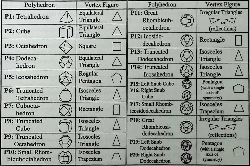
745746gon obtained by connecting the midpoints of the edges that meet at a vertex). From Table Al2.1 it may be seen that every Platonic or Archimedean polyhedron, other than Pl 1 and Pl8, has only one vertex figure. On the other hand, in the case of Pl 1 or Pl 8, there are two vertex figures that cannot be mapped onto one another without reflection.
747The vertex-mapping procedure described above will allow the handles to be ‘‘uniquely’’ determined for all the vertices in all the cases except for P12 (icosidodecahedron), P7 (cuboctahedron), and the Platonic polyhedra. For each of these seven polyhedra, the mapping of the configuration of the first vertex onto that of another vertex can be done in more than one way. This is a consequence of the shapes of the vertex figures of these seven polyhedra. To elaborate, it may be seen from Table Al2.1 that the vertex figure of each of these polyhedra can map onto itself in more than one way. In the case of these polyhedra, the handles of vertices are chosen using the following rules:
- a.
- For a ‘‘ring’’ of vertices, that is, for a circularly disposed set of vertices that lie in a plane parallel to the E-plane, the handles are chosen such that they constitute a cyclically symmetric configuration.
- b.
- The disposition of the handles for a southern ring of vertices is obtained by ‘‘turning over’’ the corresponding northern ring (and rotating it, if necessary).
- c.
- If there is a vertex whose handle is not uniquely determined by the above rules, then, among different possible handles, the one that has the smallest vertex number at the other end is chosen.
- 8.
- Each end of the handle of a vertex of a polyhedron has an associated letter. To elaborate, the end that is at the vertex is associated with the letter A and is referred to as the/l-end and the other end is associated with the letter 5 and is referred to as the S-end.
750 13
751 □ 385