2 Polyhedra, from Pythagoras to Alexander Graham Bell
2Jos Tomlow
2.1 INTRODUCTION
3Writing about the history of polyhedra up to the year 1900 means either lining up repetitive quotations from some 400 editions of Euclid’s Elements or—which the author prefers—making a voyage of exploration through historic objects and images of polyhedral shapes and considering the specialists involved. Indeed, the very materialization of polyhedral form as a two-dimensional image or a three-dimensional object turns out to be one of the keys to the significance of polyhedra in history.
2.2 NATURAL CRYSTALS
5The history of mathematics did not start with Pythagoras, who built upon the theoretical and practical knowledge of geometry that the Egyptians and the
6 Beyond the Cube: The Architecture of Space Frames and Polyhedra, edited by J. Francois Gabriel ISBN 0–471–12261–0 © 1997 John Wiley & Sons, Inc.
7 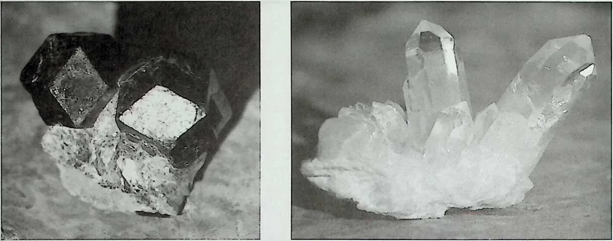 Figure 1.2 Quartz, rock crystal, with prismatic shape and pyramidal ends. (Source:
Private collection. Photo: Jos Tomlow, Stuttgart.)
Figure 1.2 Quartz, rock crystal, with prismatic shape and pyramidal ends. (Source:
Private collection. Photo: Jos Tomlow, Stuttgart.)
8 Figure 1.1 Natural crystals (Almadin) with the shape of a rhombic dodecahedron. (Source: Private collection. Photo: Jos Tomlow, Stuttgart.)
9 Mesopotamians had acquired. Even older are Chinese achievements in mathematics. If one wants to reconstruct the earliest human understanding of polyhedral phenomena, one has to think rather of natural polyhedra that occur in certain crystals. So, for a start, we may consider these naturally occurring manifestations that could have urged people to look further. Certain natural crystals show semi-regular or regular polyhedral forms like the rhombic dodecahedron, the tetrahedron, and even the cube.1 The transparent quartz crystal shows a polygonal prism with a pyramidal top. This may have led people to ponder on the geometric properties until someone may have conceived that six square planes fit together in a logical way into a cube.
2.3 THE EARLIEST POLYHEDRAL OBJECTS
11The next step is the man-made polyhedral object. One such ancient object is the East African foot ring, whose polyhedral ends may be even older in origin than the semi-regular polyhedral pyramids of Egypt or related forms in Mesopotamia. The material is hammered and welded silver. Women wore such lightweight rings loosely around the ankle. The open ring is hollow with two knob-like endings, shaped like cubes with snubbed vertices. This shape, called a cuboctahedron, is a semi-regular polyhedron with six squares and eight triangles. The craftsman took care to smooth some edges of the polyhedra in order to avoid hurting the foot, whereas all other surfaces are adorned with cut lines or stars. Typical °f this kind of jewelry worn by Berber women is its cultural origin and age are difficult to trace.2
12 Proof that the combination of an open ring with a cuboctahedron is truly
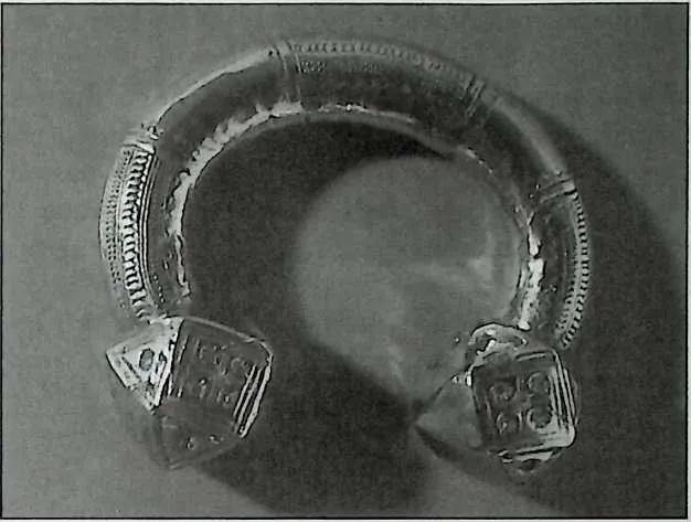
14 Figure 1.3 Old East African silver foot ring with ends shaped like a semi-regular polyhedron (cuboctahedron). (Source: Private collection. Photo: Gabriela Heim, Stuttgart.)
15 old can be found in the so-called polyhedral earrings and basket earrings produced in early medieval Europe. One pair of earrings, now in the German-isches Nationalmuseum Niirnberg, was probably found in a grave in Romagna, Italy. The material is silver wire with a tiny solid silver polyhedral knob attached to it.3 Another type of earring, an example of which is in the Landesmuseum in Stuttgart, was found near Basel in an Alamannic woman’s grave (end fifth century). One end of the so-called basket earring, made of either gold or silver, has an open cuboctahedron or similar form, in which a precious stone (e.g., garnet) is held. Although later on these polyhedral forms were copied by regional artists, their origin is thought to be Mediterranean, imported by trade or war.4
2.4 THE ANCIENT GREEKS ON POLYGONS
17In my hypothetical chronology, the ancient science of polygons and polyhedra began only after craftsmen had made simple polyhedral objects like the early cuboctahedra mentioned previously.
18 Pythagoras (ca. 570–510 B.C.) is attributed with developing a basic geometric theorem, the graphic demonstration of the algebraic formula a2 + b2 = c2. The square and the right-angle triangle play a major role in his proof.5–7To underline the importance of his work, we may recall here the story of how Pythagoras sacrificed a hundred fat oxen to the gods in gratitude for his having discovered the 90° angle.8
19 In Euclid’s Elements we find a discussion of the Pythagorean theorem. An illustration survived, dating from a time when European prints did not yet exist and can be found in an Arabic transcription of Nasr ad-Din at-Tusi (who died in 1247). If we consider the quality of the drawing, we see some interesting, progressive features: Letters permit cross reference to the text and the figure is drawn in red, whereas the lettering uses dark ink. Negative features also exist: The drawing is roughly executed with some lines shown double; the squares do not show true right angles; and the illustration is awkwardly squeezed between the accompanying text. The non-right angles are especially puzzling, as they concern the very essence of the geometric construction described. One may think that the illustration has no meaning on its own and can only be understood in relation to the mathematics in the text. We may call this a diagrammatic use of the drawn image.9
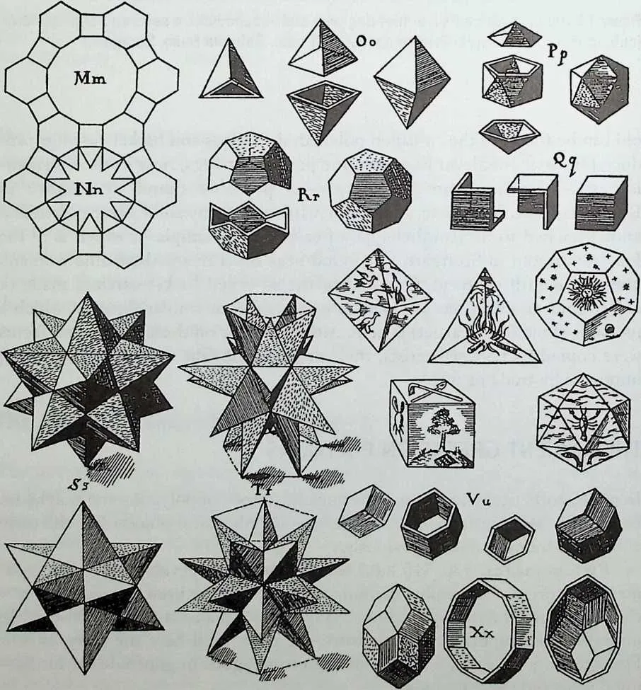
21 Figure 1.4 The five ‘‘Platonic’’ regular polyhedra and their symbolism—together with concave or stellated polyhedra—as depicted by Johannes Kepler in Harmonices Mundi (1619). (Source: J. Kepler, Die Weltharmonik, R. Oldenbourgh Verlag, Munich, 1990.)
2.5 THE ANCIENT GREEKS ON POLYHEDRA
23The Greeks started to theorize about the relationship between polygons and polyhedra and, in this way, entered into a hermetic realm of knowledge. The observation that only five regular and convex polyhedra can exist and the notion that these bodies were a symbol for all and everything were formulated as a doctrine by Timaeus of Lokri: Fire is represented by the tetrahedron, air by octahedra, 'water by icosahedra, earth by cubes and, since a fifth arrangement is possible, God has zised the dodecahedron to serve as a contozir of the zmiverse—cited from Timaeus by Plato (427–348/347 B.C.).5
24 Euclid (ca. 323–285 B.C.) described the basic geometric principles of these five polyhedra in his Elements.10,11 As we shall see, it was a long time before the visual image of polyhedra matched the mathematical rigor of Euclid. It is only from the 18th century onward that book illustrations can be regarded—more or less—as geometrically correct projections.10,12
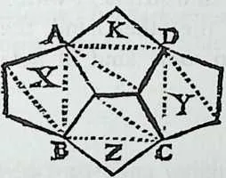
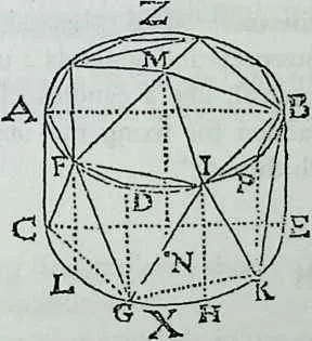
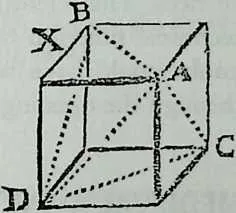
26 Figure 1.5 Polyhedra illustrations, showing poor standard of representation in 18th-century mathematical handbooks. (Source: B. Lamy, Les Elemens de Geometrie ou de la Mesure de I'etendue; qui comprennent les elemens d'Euclide;…, Paris, 1731.)
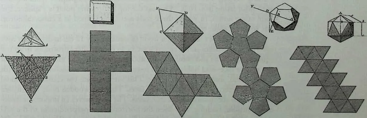
28 Figure 1.6 Polyhedra illustrations in a leading architectural handbook of the early 19th century. (Source: J. Rondelet, Traite theorique etpratique de I'artde batir, Paris, 1812–1817.)
29 Furthermore, note that it is in 320 A.D. that Pappus published the 13 semi-regular polyhedra described by the great physicist Archimedes (ca. 287–212 B.C.).6-7
2.6 ANCIENT POLYHEDRAL MODELS
31Let us return to the interesting question of polyhedra as three-dimensional objects. Referring to their autonomous beauty, Plato himself speaks in Phile-bos of the making of such objects ‘‘with a plane iron’’ and with the help of ‘‘guideline and triangle.’’13
32 In a recent contribution Malkevitch states that polyhedral objects were being made in late Roman times. He mentions icosahedra of steatite and faience with Greek letters incised on their faces.
33 Quite significant is a bronze dodecahedron found in Carmarthen, Wales (Society of Antiquaries of London). It is a hollow dodecahedron with 12 circular openings in the faces. The circular openings are of six different sizes and paired together on opposite faces. Solid spherical knobs are added on the 20 vertices. The scientific interpretation suggests a use as an instrument with a technical function or a utensil, like a candlestick. On the other hand, the knobs could have been added for fixing the object to some land of pole through the openings with thread.14
2.7 MEDIEVAL APPROACH
35Mature ingenuity is shown in the semi-regular polyhedra in the Barbarossa Chandelier in the Aachen Cathedral (ca. 1270). The Barbarossa Chandelier is one of the few remaining of this type in Germany, others being in Hildesheim and Gross-Comburg. These chandeliers symbolize the city of Jerusalem. Individual miniature towers are attached on a metal ring representing the city wall. The Barbarossa Chandelier is suspended from a chain with bifurcating iron rods. Whereas the top bifurcating point is a sphere, the four other nodes, in which three rods meet, are shaped as a cuboctahedron (six squares, eight triangles).
36 The nodes are made of solid wood (approximately 12 cm in diameter) covered by silver sheets and a sphere’s sector in copper sheet protrudes from the square faces. The rod coming from above enters the node element in one of the square faces and holds the two lower rods in a shared inclined plane with a horizontal, intermediate iron bar. This intermediate bar crosses the nodal object between two opposite square faces. Thus the wooden node was drilled crosswise to accommodate the iron parts. The node serves an important structural purpose, keeping, as it does, the horizontal bar perpendicular to the primary rod. As both secondary rods are fixed to the horizontal part with eyelet hinges, the structural solution for the chandelier and the even heavier chain,
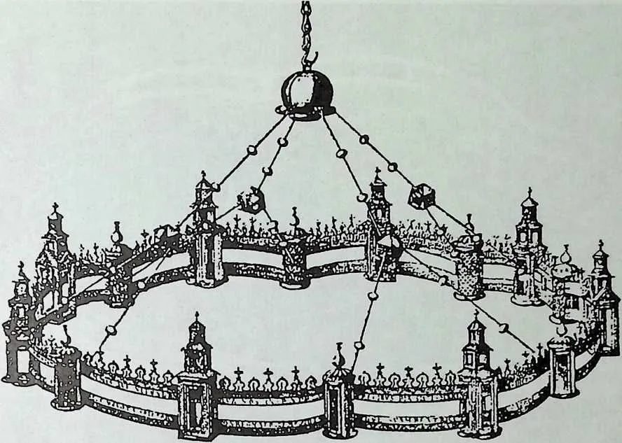
38 Figure 1.7 The Barbarossa Chandelier in the Aachen Cathedral (1170). (Source: Die Kunst-denkmaler dec Stadt Aachen, I. Das Munster zu Aachen, Dusseldorf, 1916.)
39 which together weigh 640 kg (incomplete), shows a maximum degree of freedom within a symmetrical equilibrium.15
40 Polygonal geometry is a major principle in the design, not only as applied to the node element but also in relation to the whole chandelier and even its position in the centralized space of the Aachen Cathedral, called the Octagon. The chandelier’s ring is divided into eight segments and carries eight three-story towers, alternating with smaller towers. Forty-eight lamps are regularly spaced around the wall. The bifurcation occurs in two stages: The chain carries four rods, each of which holds two more suspension rods. This geometric scheme is related to the symbolism of the holy city of Jerusalem, which shows similar features as an ideal city in terms of planning. The upper bifurcation point, a sphere, symbolizes the sun, as can be seen from texts on these chandeliers, and one may assume that the other smaller spheres and the semi-regular polyhedra could be interpreted as planets and moons in their ordered position in space.15,16
41 The inventive aspect of this application of polyhedra is that geometry is used correctly here as the basis for a spatial design. Although the angle of bifurcation of the lower rods was a free choice and is not related to the axes of the cuboctahedron, one may see in this application a very rare historic predecessor to contemporary space frame nodes developed from polyhedra.
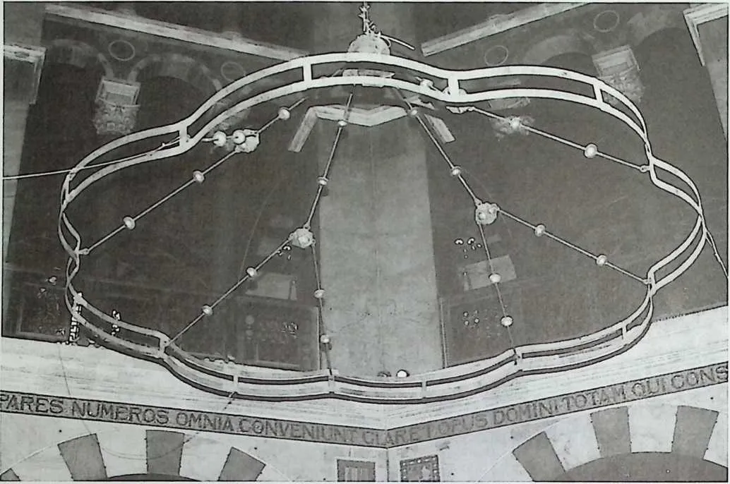
43 Figure 1.8 The structural parts of the Barbarossa Chandelier in the Aachen Cathedral (1170). (Source: Aachener Dom, Domkapitel. Photo: Herta Lepie, Aachen.)
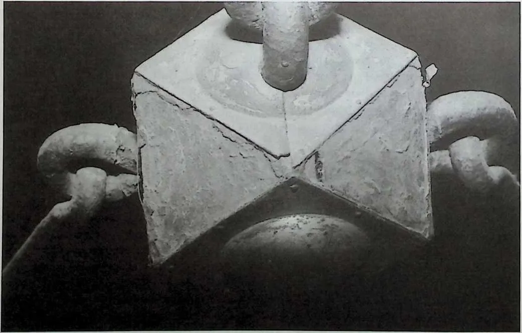
45 Figure 1.9 Semiregular shaped knot (snub cube) of the suspension of the Barbarossa Chandelier in the Aachen Cathedral (1170). (Source: Aachener Dom, Domkapitel. Photo: Herta Lepie, Aachen.)
2.8 CONTRIBUTIONS FROM THE ARABIC WORLD
47Other medieval examples of polyhedral objects are rare and there seems to have been little theoretical development during this period. This may be because Greek mathematical sources were only fragmentarily known in Europe and there was only limited communication with the Arabic world and its fruitful scientific use of Greek sources.9,17
48 Although Arabic knowledge of polygons and their use in design, for instance, in tile mosaics, was brilliant and common, no evidence could be obtained that the Arabs took the logical next step to polyhedra-based applications in three-dimensional space. However, Critchlow refers to Arabic cosmological speculations—similar to Kepler’s—based on ancient polyhedra symbolism.18
49 Of decisive importance for the understanding of three-dimensional space will be the understanding of the way in which the eye receives a certain image. On the basis of Euclid’s book on optics, Arabic authors such as al-Kindi (who died in 873) and Abu Ali al-Hasan (965–1039), known as Alhazen, contributed to the scientific understanding of basic notions like the cone of vision, the working of the pupil of the eye as a lens, and the necessity of light for visibility of any object. These Arabic books were translated for use and interpretation throughout Europe. Subsequently, Arabic knowledge on optics added to the understanding of the physical part of perspective projection in Italy, outside the tradition of its authors. Richter defends the hypothesis that a model by Alhazen showing the working of the eye was based on the torus shape consisting of polygons, which will be discussed in more detail in the following section.’’
2.9 PAOLO UCCELLO (ca. 1397–1475) AND THE ‘‘MAZZOCCHIO’’
51As Gothic gave way to the Renaissance, a Florentine painter named Uccello became interested in the main problem of early Renaissance painting: perspective. Vasari describes Uccello as an artist who should have given less time to geometry and more to painting.19 Uccello’s fascination with perspective and geometry led him to concentrate on details. Overall, his paintings show a complex composition with several different perspective vanishing points.20
52 Drawings from his hand show objects, often of circular shape, reduced to quasi-polyhedral forms. His favorite is the torus shape, not as a pure abstract form but depicted in some paintings as the cylindrical hat worn by the men of his time, the so-called ‘‘mazzocchio.’’ Preparatory drawings of such faceted rings measure up to 20 cm and are extremely precise perspec-tival projections in ink. The rings, sometimes enriched by pyramidal forms, are divided into 16 or 32 sectors and each ring’s cross section consists of a regular hexagon or octagon. Because all points of the ring are shown in most of these drawings, the ring appears transparent, much like today’s CAD line
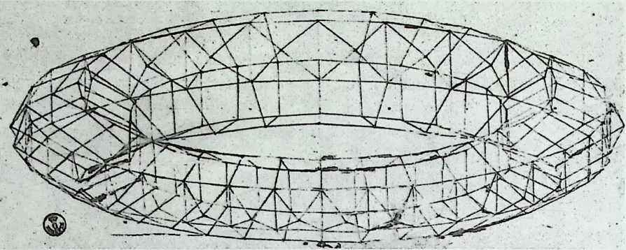
54 Figure 1.10 Perspective ink drawing of a faceted ring, seen from below, attributed to Paolo Uccello (1397–1475). (Source: F. Borsi and S. Borsi, Paolo Uccello, Florenz zwischen Gotik und Renaissance, Belser Verlag, Stuttgart, Zurich, 1993.)
55 drawings. The reason for the consistent use of this drawing method may be to show up any mistake in the perspective projection of the ring through a disturbance in the continuity of the lines. Afterwards these drawings could be copied with all hidden lines eliminated. The drawings are in one-point perspective and they have an axis of symmetry common to two of the sector borders. In his painting Bernardino della Ciardi Pushed out of His Saddle (part 2 of The Battle of Sail Romano), four men with such hats are depicted from various points of view. In order to emphasize the geometric structure, the hats’ facets are colored like chessboards.20
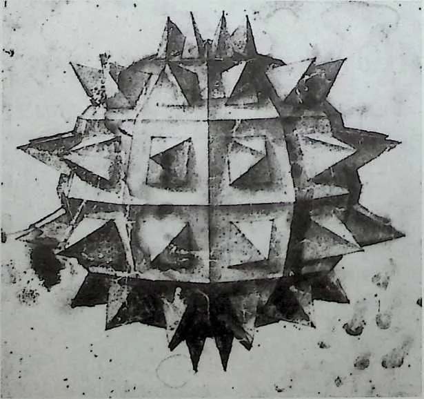
57 Figure 1.11 Drawing of a 72-faceted irregular polyhedron with pyramid points attributed to Paolo Uccello (ca. 1440). (Source: F. Borsi and S. Borsi, Paolo Uccello, Florenzzwischen Gotik und Renaissance, Belser Verlag, Stuttgart, Zurich, 1993.)
58 The epitome of these studies is a drawing of a vase with 32 sectors and some 64 nodal points in its section. Another very interesting drawing—similar to some of the other drawings not positively identified as Uccello’s but executed according to his drawing method—is a ‘‘sphere with diamond pyramids.’’13,20,21 The sphere turns out to be a 72-faceted irregular polyhedron. Another depiction of a polyhedron—a stellated dodecahedron surrounded by a polyhedral ring—is attributed to Uccello. It is a colorful floor mosaic in the basilica of San Marco in Venice dating from 1429–1430.22
2.10 PDERO DELLA FRANCESCA (ca. 1420–1492) AND HIS PERSPECTIVE LESSONS
60Unlike Uccello—who often placed the boldly drawn volumes of his figures in dark and somewhat ill-defined settings in his paintings—Piero della Francesca, one of the major Renaissance painters, achieved an impression of perfect harmony by using lighter colors and placing his figures in clearly defined architectural settings masterfully rendered in central perspective.23
61 In his old age when almost blind, he produced a work on perspective De Prospectiva Pingendi, dictating the text to a pupil, who also executed the drawings. Being a major source of publications by Albrecht Durer and Luca Pacioli and of La Pratica della Perspettiva (1569) by Daniele Barbaro, this work was highly influential. It was through it and the others that many artists and architects learned about perspective and geometry.13,24
62 Piero della Francesca’s didactic approach is characterized by great care in the choice, composition, and manner of execution of the illustrations. In the Codex Palatin manuscript, in order to make the procedures as clear as possible, the construction fines are drawn in red and the finished perspectives of the objects in black. The geometric construction of the mazzocchio torus form (here called ‘‘torculo’’) is explained as well as that of a polyhedral cupola similar to Uccello’s 72-faceted polyhedron. However, the text is very dry and tedious, consisting of page-long listings of the points to be connected as the construction proceeds.25
2.11 LUCA PACIOLI (ca. 1445–1517) AND THE MODEL APPROACH
64The theology professor Luca Pacioli from Borgo San Sepolcro (hence who was also known as Fra Luca di Borgo) was involved in a research project for the Duke of Urbino, Guido Ubaldo, and Bishop Valletari, seeking to define correctly the mathematical shapes of polyhedra, which were thought to have high symbolic significance. His scientific publications included the first Italian translation of Euclid’s Elements.13,24
65 A new departure in the search for representation is the devising of different kinds of models of polyhedra. Pacioli’s method of working essentially develops new forms by truncation (cuboctahedron) or addition (stellated poly-hedra). His presentation of results is unique for his time. One can distinguish no fewer than four levels of presentation in his book De Divina Proportione (1497), which was highly influenced by Piero della Francesca. First, there is the text, a mixture of dry descriptions of mathematical relationships and witty accounts of architectural praxis. In this text a treatise on the golden section is followed by a discussion of polyhedra and their variants. Second, the text contains figures, which are simple line drawings of the schematic Euclidean type, without proper perspective or perpendicular projection when they show three-dimensional forms. Third, there are correct perspective drawings of the more complex stellated polyhedra, drawn on Pacioli’s request by Leonardo da Vinci, one of his many artist friends.21 These drawings were based on the fourth level of Pacioli’s presentation, the three-dimensional models of polyhedra. Even a fifth level of presentation is allowed for by leaving ample white space around the printed parts on the pages, to enable the reader to add his or her own sketches or notes.8
66 In his book Pacioli refers to the usefulness of perspective drawings and he especially recommends that the reader should visit the models in a sort of exhibition room or laboratory.
67 He describes the models—which were lattice structures—as being suspended and in his perspective drawings Leonardo took care to show how they were suspended with thin threads. The fact that the models were suspended may have practical reasons. As we know from experience, lattice models are rather vulnerable to deformation. By suspending them, one ensures that only their own weight is loading the structure. Even when somebody touches one, it will simply swing until balance is recovered again.
68 Other information provided by Pacioli in Chapter LXX of De Divina Pro-portione is that the Latin names of the polyhedra were written on paper labels attached to the suspension threads of the models with two pegs (of amber, which is extremely fight). He humbly excuses himself for the poor material he had to use for his models, owing to a lack of funds, and he remarks that the noble theme of polyhedra deserves to be proclaimed in precious metals decorated with precious stones.8
69 The monk Pacioli’s interest in polyhedra is further documented in a double portrait painting by Jacopo de’ Barbari (1495), showing him with a young nobleman in the role of a pupil.13,24,26 A solid wooden dodecahedron is shown on a desk with other objects relevant to geometry and drawing. Of particular interest is the model of a semi-regular polyhedron—a rhombicuboctahedron, as Kepler named this shape, made of 18 squares and 8 triangles. This polyhedron of glass polygons, probably blown in one piece, is half filled with water. A thread crossing the glass bowl in its center is fixed to its bottom and suspends it in an unstable equilibrium from the ceiling. It should be remarked, however, that, in an otherwise perfect painting, the polyhedron shape is flawed with a small perspective mistake: The water level is not parallel with the top and bottom triangles.
70 This water-filled glass polyhedron can be interpreted as a measuring device, making use of physical laws. Because the suspension is vertical and the water level horizontal, any horizontal section of the polyhedron can be generated by varying the amount of water and the result can be compared with drawings. This polyhedron and its geometric construction—without referring to the model—is explained in De Divina Proportione, Chapter LIU. Another example of Pacioli’s concern for the physical aspects of his models is that he mentions the possibility of enlarging the form by adding triangular or square pyramids, leading to stellated shapes that will always stand on the tops of three pyramids ‘‘as one can verify by observation on the materialized shape.’’
71 The 72-faceted polyhedral sphere, already mentioned in the discussion of Uccello’s work, is presented in Chapter LIV Pacioli points out that domes like that of the Pantheon in Rome with its faceted coffers may be regarded as being derived from a similar geometric approach.
72 Pacioli’s aim in his concise presentation of stereometry was to advocate the training of good craftsmen and he indicates this by warning anecdotes. In Chapter LVII he recounts that he, together with a painter, once convinced a client to build a pillar capital in a polyhedral form for its aesthetic impact. The master builder—thinking it would be an easy job—followed the proposal, but in twenty days of work many marble blocks were spoiled and compensation had to be paid. This awkward situation was only resolved when Pacioli offered to teach the workers about polyhedra. A modest type of polyhedra-based decoration by Pacioli is diamond-faceted masonry, probably developed from a dodecahedron.24
73 In a rather mean way—typical of the feeling of superiority of the academic toward the common worker—Pacioli proposes in Chapter LVH to expose the ignorance of stonemasons by asking them to make a regular shaped block with 12 regular polygons, but using no pentagons.
74 In Chapter XVIII of his book De Architectlira (1509), Pacioli again encourages architects to build pillar bases and capitals according to polyhedral forms. He mentions Roman literary references to the famous sculptor Phidias from Cercio, who executed a part of a work in icosahedron shape (the symbol of water). This icosahedron attracted the speculative attention of philosophers, more than any other part of his outstanding work.8
75 Yet only few architects of his time followed Pacioli’s optimistic vision of polyhedra. Vasari reports about Michelangelo (1475—1564) that he ‘‘had the goldsmith Piloto make a ball of seventy-two facets’’ as a decorative finial for the cupola of San Lorenzo.19 An illustration of the ball consisting of irregular triangle planes is shown in Mainstone’s book.27
2.12 LEONARDO DAVINCI (1452–1519) AND THE LATTICE STRUCTURE
77Leonardo da Vinci’s illustrations for Pacioli’s De Divina Proportione were probably the first to show polyhedra as lattice structures.21,28 Drawing the edges of a polyhedron with more than one line allows the artist to show which edges are in front and which are behind, which is a great help in visualizing structures in space.
78 Leonardo’s skill as a draftsman shines especially in his drawings of machines and complex building designs and there is clearly a connection between his illustrations for Pacioli of latticed polyhedra and his linear stereometric images of architectural structures.29 Compare his drawings from the Codex Atlanticus: f. 190 r-a, f.3 v-b, and £.335 v-e.
2.13 ALBRECHT DURER (1471–1528) AND THE CLEARING OF POLYHEDRAL IMAGES
80Diirer’s interest in polyhedra is well known from his copperplate engraving Melancholia of 1514. In Melancholia an angel contemplates an oversized truncated stone block in a puzzling setting referring to building praxis, eternal time, and religion.
81 Being influenced by humanist philosophy and Renaissance universalism, Diirer was fond of any geometric problem relating to art. Around 1506 he visited Italy for the second time and he himself tells of a master in Bologna who taught him the ‘‘secret perspective.’’ This master is thought to have belonged to the circle around Pacioli. In Venice Diirer bought a Latin copy of Euclid’s Elements in order to understand the theoretical background of his newly acquired knowledge.13,24, 30,31
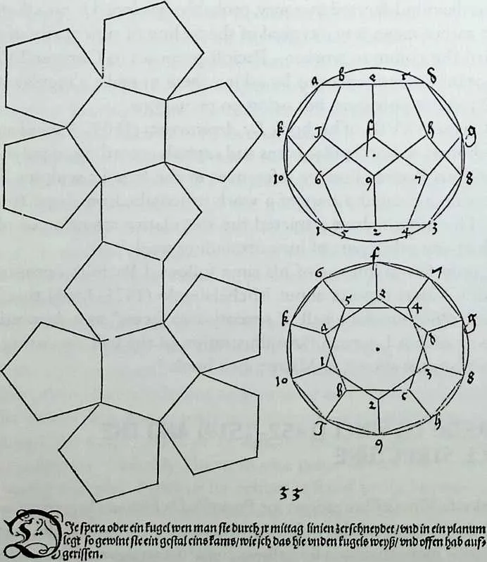
83 Figure 1.12 Albrecht Diirer: projective image of a dodecahedron and a cutout plan for a paper model, as depicted in Underweysung der Messung (1525), fourth book, Fig. 33. (Source: A. Diirer, Unterweisung der Messung, Verlag Dr. Alfons Uhl, Nordlingen,1983.)
84 In the fourth book of his Underweysung derMessung (1525), polyhedra are illustrated in a new way. Here, Durer, probably the most able woodblock cutter of all time, developed a layout of beautifully worked out lettering with ample space for the illustrations. As in other figures, polyhedra are shown by line drawing of plan and section, representing the body, as it were, transparent. Letters facilitate the understanding of the drawings. Other figures show chains of polygon plans, which can be cut out to make paper models.32
85 Diirer’s clear-looking images of polyhedra nevertheless often contain mistakes, showing that he was not quite aware of the mathematical rigor of geometry. For example, he draws the circumscribing circle of the polyhedral body as if the two-dimensional projection in plan or section would touch it in all its vertices. Being an artist teacher, his major aim may have been to give a clear, methodical description rather than to show exact geometry. Similar criticism may be made of his description of the conical section, the ellipse, to which he gives the name ‘‘eyerlini’’ (egg line) because of the asymmetrical result in his drawn construction. Later Kepler will point out that Diirer’s ‘‘egg line’’ should be interpreted as a bisymmetrical form when speaking about the ellipse.24, 33, 34
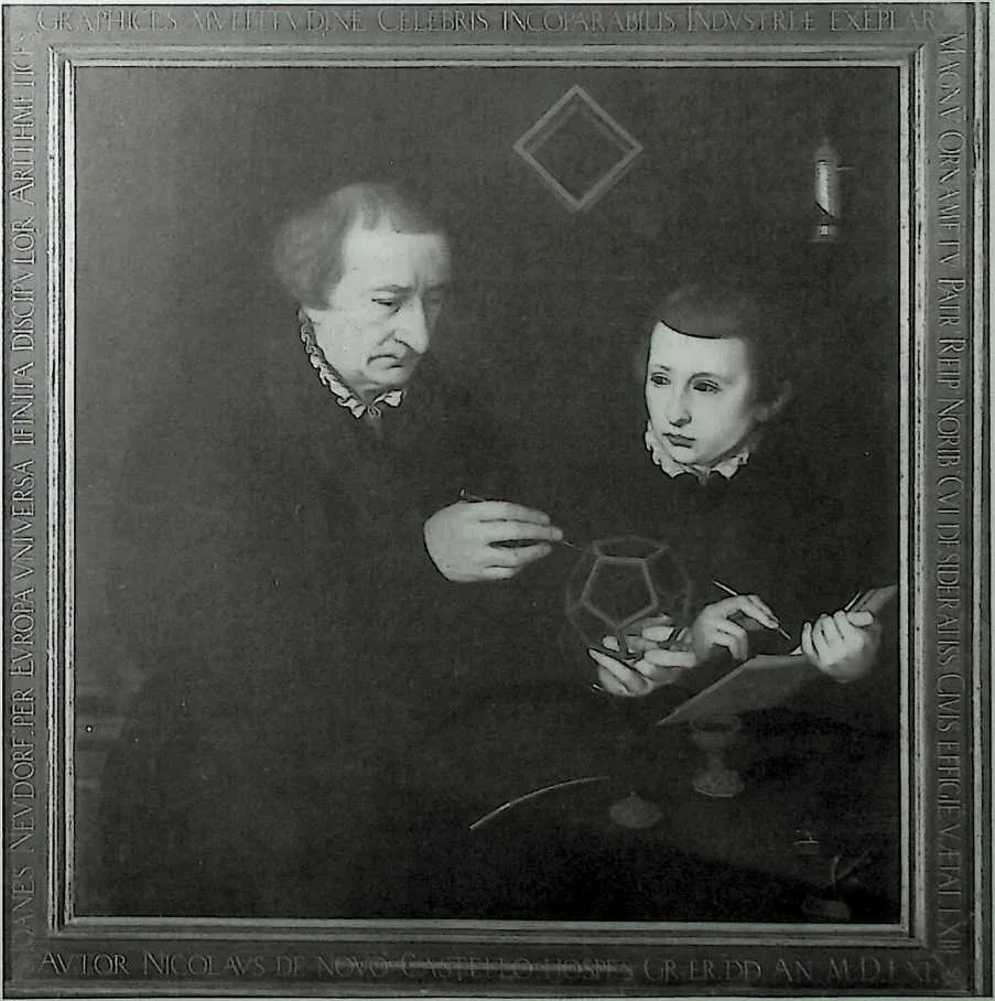
87 Figure 1.13 Nicolas
88 Neufchatel: Portrait of the Calligrapher and Mathematician Johann I Neudorfer and His Son (1561), both studying a lattice model of a dodecahedron. (Source: German-isches Nationalmuseum, Niirnberg.)
89 Yet Durer’s method of drawing polyhedra and conical sections was far more accurate than the illustrations in early manuscripts or editions of Euclid’s Elements, which often seem to be mere diagrammatic adjuncts to the mathematical text.
2.14 JOHANN NEUDORFER (1497–1563) AND THE DDDACTBC MODEL
91The founder of German calligraphy and a teacher of calligraphy as well as calculation was Johann Neudorfer (1497–1563) from Nurnberg. He executed the text for Durer’s print series Apostles. A painting (Germanisches Nationalmuseum Nurnberg) by Nicolas Neufchatel (1561) shows Neudorfer as a mathematician, measuring with compasses a dodecahedral lattice model of approximately 20 cm diameter, while Neudorfer’s son writes down the results. A cube model is seen hanging on the wall.
92 The dodecahedron in the painting shows a profile in L-shape for the bars?1 This may, on the one hand, save some weight in comparison with a simple trapezoidal profile. On the other hand, it makes it easier to close the faces with pentagon-shaped boards for demonstration purposes.
2.15 WENZEL JAMNITZER (ca. 1508–1585) AND RENAISSANCE AESTHETICS
94Durer’s hometown of Nurnberg offered the best quality in book production and art printing. Nobody was more fond of generating new polyhedral configurations than Wenzel Jamnitzer, a gold-and silversmith and instrument maker, who was also from Nurnberg.
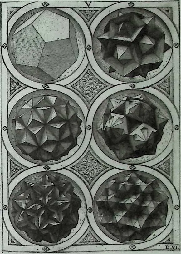
95 His perfectly produced book Perspectiva Corporum Regularium (1557) shows a large quantity of variations, generated from the five regular polyhedra. Beautifully adorned images of the Platonic symbols (fire, air, water, earth, universe) with short texts introduce four pages with six polyhedral variants for each polyhedron. Each of them is represented inside a hollow half-sphere.13 The second part of the book shows polyhedral ‘‘fantasies’’ in architectonic arrangements: for example, a monumental grave, diamond-like faceted cones, and a latticed dodecahedron on a richly worked base.
96 In Jamnitzer we recognize an artist with a systematic approach to geometry but ignorant of scientific language. Jost Amman, a copperplate engraver, executed Jamnitzer’s designs with precision.35 Jamnitzer’s method of inventing and drawing complex polyhedra is known, although he did not describe it himself. Using simplified models of polyhedra, he drew a correct image based on the empirical perspective method described by Diirer. On the basis of these drawings, he could generate variations by connecting different nodes or surfaces.
97 Portraits show Jamnitzer as an elderly looking, rather heavyset man with
98 Figure 1.14 Wentzel Jamnitzer: allegory on ‘‘Water,’’ Plato's symbol of the icosahedron, from his Perspective Corporum Regularium (1568). (Source: Germanisches Nationalmuseum, Niirnberg.)
99 Figure 1.15 Wentzel Jamnitzer: dodecahedron variants (1568). (Source: Germanisches Nationalmuseum, Niirn-berg.)
100 Figure 1.16 Jost Amman: engraving print of Wentzel Jamnitzer working on his installation to analyze perspective (ca. 1568). (Source: Germanisches Nationalmuseum, Niirn-berg.)
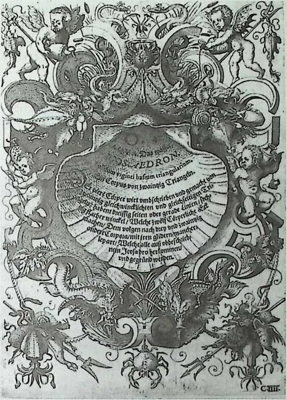
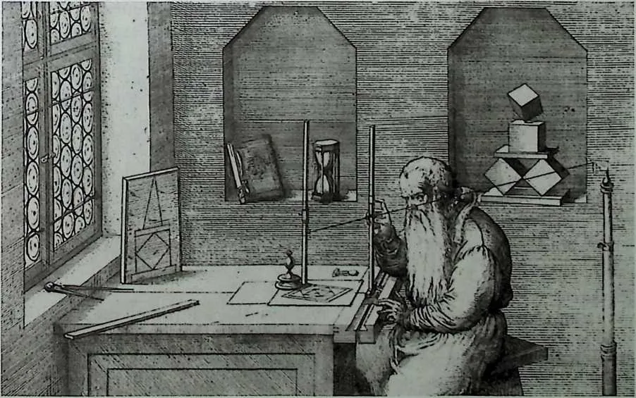
102 a long beard. It is amazing that a person with such a physiognomy could—like some brilliant pianists with short thick fingers—produce the most delicate work of such natural beauty. Of his silverwork it was said that he could make trees with miniature leaves that were of such fine workmanship that they would move when one blew on them.
103 Jamnitzer’s instruments were also inventive and precise. The portrait by Jost Amman in a copperplate print (ca. 1568) shows Jamnitzer with his perspective apparatus. From a given viewpoint—the top of a pole on the right—a thread is stretched to the object to be drawn and is held by a vertical stick with a foot plate on the other side. The thread is kept under tension by a free-hanging weight inside the pole. (Another possible interpretation is that the weight hangs in front of the pole but is not shown in the print.) A second vertical stick, with a small console that can move vertically, is attached on a rail. The console’s end, fixed by a vertical stick and horizontal rail, gives the coordinates of one of the points on the projection surface of the drawing. By changing the direction of the thread toward other marked points of the object, all necessary points of the drawing can be determined and measured. A special aid was a plate with the drawing pinned on it, which is fixed with a horizontal hinge parallel to the rail on the table. If one turns the drawing into a vertical position, the console could make a small hole to mark the corresponding point on the paper. To permit turning the paper vertically, the thread and its lower fixture would have to be turned away temporarily.36
104 The polyhedral construction in the niche shows a model that Jamnitzer might have used to draw his polyhedra variants. The model, of rather modest appearance, is of some mathematical interest as showing the cube in three different positions of balance—stable on a face and unstable on an edge and a vertex.
105 As an instrument maker, Jamnitzer would have been accustomed to improving an existing apparatus and his perspective instrument should be regarded as a product of his cooperation with other perspective researchers in the Niimberg circle, such as Hans Lencker, Lorenz Stoer, and Hans Hayden. This development of perspective instruments was known and illustrated by Paulus Pfinzing in Ein schoner kurtzer Extract der Geometric und Perspectiva (1598, privately printed with handdrawings) and later published with woodcut illustrations as Optica (1616).13,36
106 Both the goldsmith Jamnitzer with his work in gold and silver and the engraver Jost Amman were famous artists who worked for the imperial family. One wonders why such an odd book project on abstract polyhedral shapes was established. The engravings by Jost Amman mostly depict historic events and people against a background of architecture or landscape with decorative embellishments.
107 Apart from the preparatory drawings for the book illustrations, Jamnitzer’s remaining working drawings only once (in the Berlin Sketchbook, page 21) show a sketchy representation of some polyhedra.36 The isolated position of his polyhedra studies in relation to his usual themes leads one to interpret Jamnitzer’s purpose as the creation of a training method for drawing three-
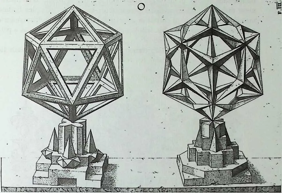
109 Figure 1.17 Wentzel Jamnitzer: polyhedral fantasy (1568). (Source: Germanisches Nationalmuseum, Niirnberg.)
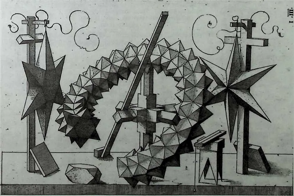
111 Figure 1.18 Wentzel Jamnitzer: monumental grave as a polyhedral fantasy (1568). (Source: Germanisches Nationalmuseum, Niirnberg.)
112 dimensional objects. In his design work, both as a goldsmith and as an instrument maker, Jamnitzer needed a precise representation of complex bodies, including any volume of curved or angular appearance and multisymmetric relationships. Apart from this, scholars characterized the book type as a pattern catalog for use by artists.13,37,38
113 Jamnitzer’s symbolic interpretation is the best example of the aesthetic approach to polyhedra typical of the 16th and 17th centuries.
114 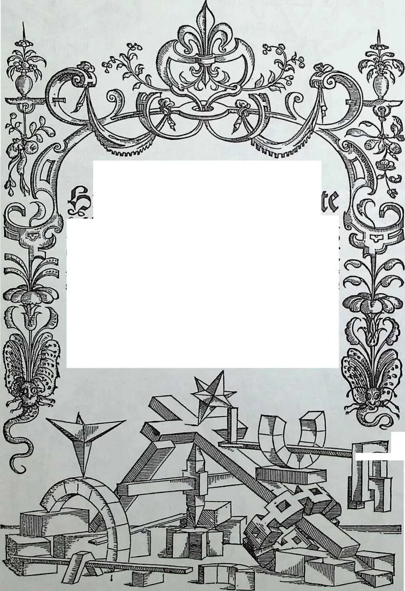 &efc$2te&en/ mitepempclnavffnct fcnban
tag gegeben tvirb/ei n newer befonber turner/ bodj gcrecfjter onnb
feln leicfcter weg/roie allerlep bing/ea ffren (£oxpoxa/©ebe ro/ober
wa$ mdglidj juerbemfenvnbingrunbju(egeni(i/venucftober
enuerruef t/ferner in bit Pcrfpcetpf gebxacfjt werben mag/ on eini«
ge sergeblice linie/rip vff puneten/xcbergleicften weg biffitio noefc
nit betant gewcfen/ ©urefj fianfen_£encferQ3urger
ju$?iirmberg/allenfieb(jabern guter tflnflen
Ju e(nen vnb ge fallen publieirt.
115 Figure 1.19 Hans Lencker: front page of his Perspec-tiva (1621), depicting technical applications of polyhedral forms like sundial, balance, wheel axis, and chain. (Source: Germanisches Nationalmuseum, Niirnberg.)
116 'WWW \\\_\\\
117 [Srwj]
118 PERSPECTIVA
119 ttK5m.2ey.C50ay.freibeit/ auff feebsfar.
©ebxutft ju Shlrmberg/ burdj Sictricfe ©crlafc.
120 M. D. LXXI.
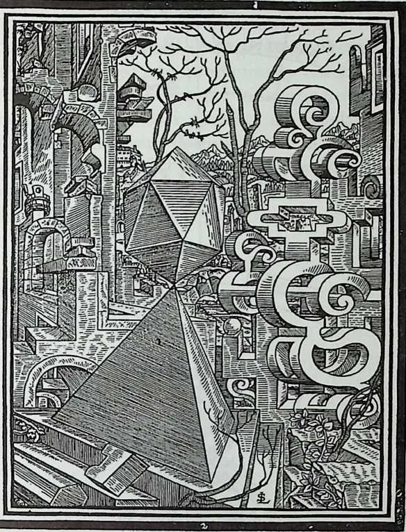
122 Figure 1.20 Lorenz Stoer: polyhedral fantasy from his Geometria et Perspectiva (1567).
123 (Source: Germanisches Nationalmuseum, Nurnberg.)
2.16 JOHANNES KEPLER (1571–1630) AND POLYHEDRAL NOMENCLATURE VERSUS COSMOLOGY
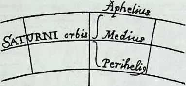
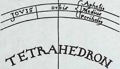
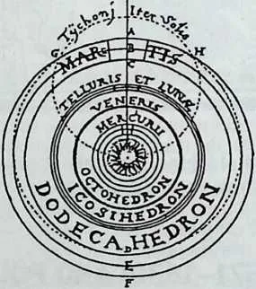
125One of the sadder chapters in the history of science is the retrograde emphasis on polyhedra in Kepler’s cosmology. As a physicist of Newtonian stature, he made a major contribution to astronomy by showing that the orbits of the planets were ellipses having the sun as one focus. However, his pursuit of the idea that the distances of the planets from the sun were proportionate to the dimensions of the five regular polyhedra nested inside one another was, in retrospect at least, a stultifying mistake. Even when empirical observations did not seem to fit this idea, he defended it with great logical ingenuity, seeing no inconsistency between doing this and indulging in furious polemics against those astrologists who saw metaphysical meaning in certain number combinations.39
126 However, as a positive result of his otherwise fruitless battle, Kepler contributed to the best known astronomical tabellarium of the day, that of Tycho Brahe (1546–1601), and in his book Hormonices Mundi (1619) he discussed new concave polyhedral solutions and developed a systematic Latin nomenclature, which is still in use today.39–41

128 BUS'
129 Figure 1.21 Johannes Kepler: representation in Harmonices Mundi (1619) of Kepler's speculative theory that the planets have the same distances as regular polyhedra, which fit exactly to each other. (Source: J. Kepler, Die Weltharmonik, R. Oldenbourgh Verlag, Munich, 1990.)
130 LORENZ ZICK (1594–1666) AND POLYHEDRAL SCULPTURE AND TOYS
131 In the early 17th century, the mathematical story of polyhedra and the precise depiction of
their shapes reached maturity. Craftsmen (fine wood turners), silversmiths, and ivory workers
found an interest in the possibilities they offered. The increasing complexity of geometry in
Renaissance and early baroque art and a general fascination with machinery contributed to this
interest.42'44 In some European courts turning craft had become part of the modern
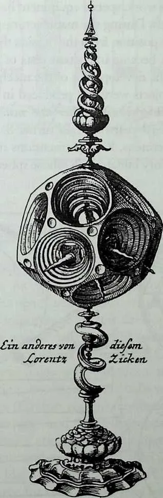
teaching
system and some noblemen—like August of Saxony (reign 1553–1586)—were taught in the
preparation of ivory objects on turning machines.
132 In Historische Nachricht von den Niirnbergischen Mathematicis und Kiinstlem (1730), Doppelmayr published some sculptures by Lorenz Zick. The central part of one sculpture is a body with some concentric parts inside, which can all turn separately. Twelve circular openings are regularly located on the sphere’s surface. Hence one could describe this form as dodecahedral. Doppelmayr refers to the making ‘‘of all kind of polygonal bodies, which are much alike the dodecahedron and which have inside them 8, 10, 12, 16 identical bodies…and which later often were copied.’’45
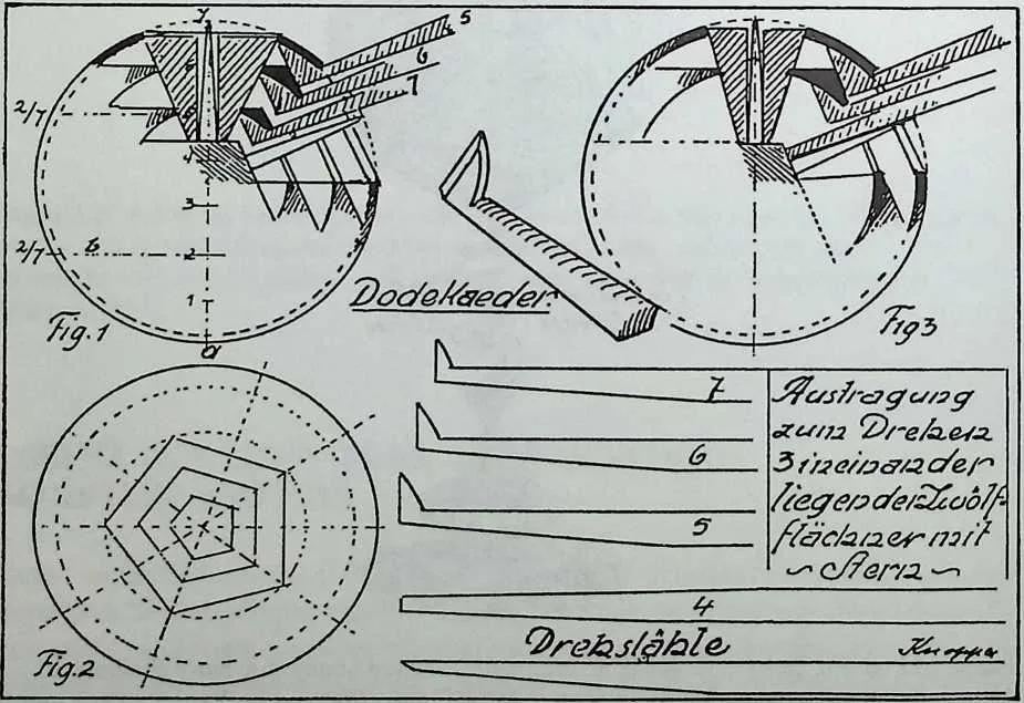
134 Figure 1.22 Lorenz Zick (1594–1666): dodecahedron-based concentric ivory showpiece with stellated nucleus as published by J. G. Doppelmayr, Historische Nachricht von den Niirnbergischen Mathematicis und Kiinstlern,…, Niirnberg, 1730, Tab. 5 (Source: Wurttem-bergische Landesbibliothek, Stuttgart. Photo: Joachim Siener.)
135 In spite of Doppelmayr’s statement, which suggests that these polyhedral ivories were invented in Niirnberg, such ivory polyhedra were already being made in Dresden around 1581 by the court turner Georg Wecker, who came from Munich. Other important artists were Giovanni Ambrogio Maggiore from Milan and Egidius Lobenigk, probably from Cologne. Beautiful specimens were produced in Dresden until 1620, many of which were recently restored and can be seen in the famous Grime Gewolbe museum in Dresden. A certain contribution to the unique quality of the Dresden samples may be attributed to Niirnberg artists such as Christof Koller, who was charged in 1559 with the installation of the first turning workshop in the Dresden court, and Hans Lencker, who from 1576 onward gave lessons in perspective related to the problem of turning ivory.44
136 To complete such fine work, special equipment had to be developed, including spherical curved chisels. During the manufacturing process, the spheres had to be fixed in a concentric position from the outside through the openings. Such applications of polyhedra became important tests of mastery in fine carpentry and thus contributed to the development of the mechanics of precision.43
137 Similar polyhedral objects were still produced in the 20th century and the book Drechslerkunst—Meistertechniken alter zmd neuer Zeit by Hugo Knoppe (1929) is dedicated to the 70-year-old artist turner Saueracker from Niirnberg, who made many fine specimens. Knoppe mentions that the polyhedral objects were derived from used ivory billiard balls whose spherical shape was damaged.43
139 Figure 1.23 Hugo Knoppe: working drawing and special chisel equipment for concentric dodecahedra (1926). (Source: H. Knoppe, Meistertechniken derDrechslerkunst,\/er\ag Th. Schafer, Hannover, 1986.)
140 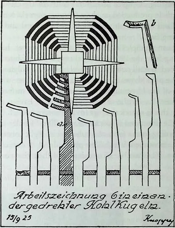 Figure 1.24 Hugo Knoppe: working drawing and special chisel equipment for concentric
spheres, similar to the Chinese examples (1926). (Source: H. Knoppe, Meistertechniken der
Drechslerkunst, Verlag Th. Schafer, Hannover, 1986.)
Figure 1.24 Hugo Knoppe: working drawing and special chisel equipment for concentric
spheres, similar to the Chinese examples (1926). (Source: H. Knoppe, Meistertechniken der
Drechslerkunst, Verlag Th. Schafer, Hannover, 1986.)
2.17 THE CHINESE ‘‘DEVIL’S WORK BALLS’’
142The ivory ‘‘devil’s work ball,’’ as the Chinese call it, is the most famous of all polyhedra-based objects. As we have seen, knowledge of polyhedra was acquired only slowly in Europe. Euclid’s Elements and the development of perspective were of decisive importance for this development. However, in nonEuropean cultures with a proper mathematical science—for instance, among the Arabs, the Mayas, and in cultures of India and China—perspective analysis of comparable rigor was unknown. Therefore, it seems important to ask how the tradition of carving these concentric balls was established in China.
143 In the south of China (Canton region), concentric ivory balls have been carved since the 14th century and direct European influence is unlikely.46 First, no European examples are known from that age, and, second, there seems to have been little cultural contact other than indirect trade at that time, apart from rare examples like Marco Polo’s visit to China in the late 13th century. The most likely source for the Chinese may have been their own earlier handicraft techniques for the carving and turning of precious stone (jade), wood, and ivory. Ivory has been carved since very early times, as it is a very fine-structured material and yet soft enough to be carved.
144 Another hypothesis is that the influence of China on the European examples resulted from colonial trade. Some literature suggests such influence and interesting examples of cultural contacts are cited after 1500 for comparable artistic production, such as Chinese porcelain imitated in Portugal and Holland or the mutual influence of Portugal and West Africa in the ivory-carving field.47
145 The European examples of Zick and others, however, have some major features differing from the 19th-century examples from China. The European examples referred to until now are positively based on polyhedra. The exterior surface of the parts shows the shape of a dodecahedron, with a hole in the middle of each of the 12 pentagons, whereas the inside surface is spherical.
146 Chinese examples consist of true spheres, each having an exterior and interior surface that is spherical, apart from decorative relief. Often they have 14 holes, like the illustrated modern example. The 14 holes are conceptually organized according to the faces of a cube and its eight corners, and on each of the cube’s six faces there is a shallow pyramid. All 14 corner points touch a common sphere. The number of openings and their size correspond to the
147 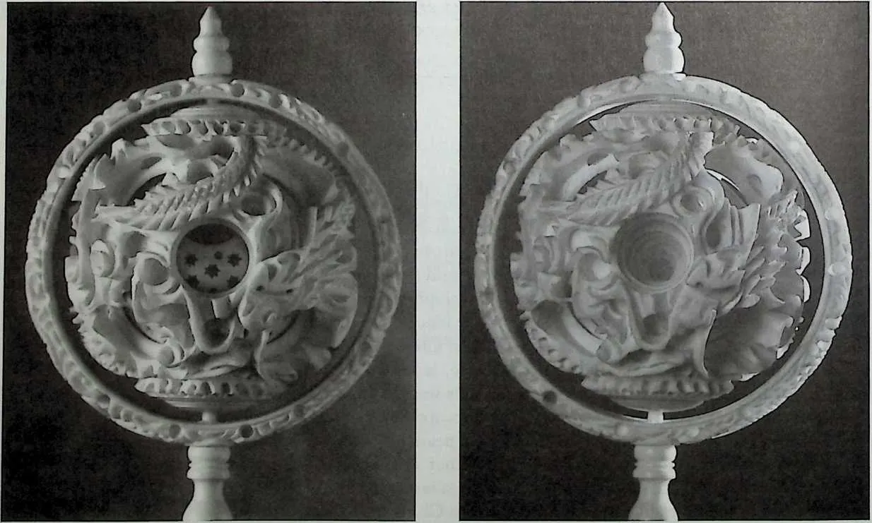 Figure 1.26 Ivory ‘‘devil's work ball’’ with all holes in common axes (Hong
Kong, contemporary). (Source: Institut fur leichte Flachentragwerke (IL), Stuttgart
University. Photo: Gabriela Heim, Stuttgart.) specially shaped chisels, which have to
carve a large enough spherical sector to loosen all material between two concentric
spheres.43
Figure 1.26 Ivory ‘‘devil's work ball’’ with all holes in common axes (Hong
Kong, contemporary). (Source: Institut fur leichte Flachentragwerke (IL), Stuttgart
University. Photo: Gabriela Heim, Stuttgart.) specially shaped chisels, which have to
carve a large enough spherical sector to loosen all material between two concentric
spheres.43
148 Figure 1.25 Sphere-in-a-sphere object with eight independent turning concentric parts—a ‘‘devil's work ball,’’ as the Chinese call it—made out of one piece of ivory. The holes are divided like the 14 vertices of a semi-regular polyhedron (Hong Kong, contemporary). (Source: Institutfur leichte Flachentragwerke (IL), Stuttgart University. Photo: Gabriela Heim, Stuttgart.)
149 Some speculation on the function of such objects may also be appropriate. They are showpieces in the first place: a demonstration of handicraft virtuosity.42,46 However, one can also regard them as puzzles. Tiny fingers or thin sticks may turn the spheres separately through the openings. Every puzzle or play has a purpose, and in this case the first goal may be to find a position for all spheres with one opening on a common axis. One can reach this goal rather easily. The final goal would be to turn all spheres into such a position that all their openings are organized in the same position as the outer sphere’s holes. In this way the initial impression of a massive sphere will change into an image of a ball that seems transparent through its core. In the case of the contemporary Chinese example, the final goal is rather difficult to reach, because its semi-regular geometric organization with 14 holes shows two different distances between the holes.
150 The Chinese system is finer because interior and exterior surfaces are all really concentric, whereas the European system shows a polyhedral outer form for each ball, which must be able to turn freely inside the next larger ball with an inner spherical surface. Thus, in the European example, some material waste cannot be avoided. Consequently, the number of parts that can turn around differs: Modern examples of the Canton region reach up to 45 spheres. A sphere that consisted of 25 concentric pieces was exhibited at the Panama-Pacific World’s Fair in 1919.48
151 On the other hand, some European examples are spherical like the Chinese balls and we can find no topological differences between these and the Chinese specimens.43
2.18 BROOK TAYLOR (1685–1731) ON PERSPECTIVE PROJECTION OF POLYHEDRA
153One of the few English contributors to the development of perspective geometry is Brook Taylor, a Cambridge Doctor of Law, who was also interested in polyhedra.
154 His Linear Perspective (1715) and Nero Principles of Linear Perspective (1719) take a more abstract approach than most books, which derive an object image by parallel projection from plan and front view. Taylor’s approach integrates images as perspective projections on a plane.49
155 In these rather short books Taylor prefers to take polyhedra as his examples for demonstrating perspective projection, probably because the distorted plans of a point-symmetrical polyhedron can be understood more easily than similar plans derived from a nonsymmmetrical object, such as an architrave piece resting in an inclined position on a stone block.
156 Although his geometrical work is considered difficult and his method painstaking, Taylor became quite famous. An illustration of polyhedra in an architectural setting in Thomas Malton’s A Compleat Treatise on Perspective (1779) reminds us of Taylor’s interest.49
2.19 MAX BRUCKNER (1860–1934) AND HIS PAPER MODEL COLLECTION
158In the preface of his book Vielecke und Vielflache—Theorie und Geschichte (1900), Max Bruckner explains that the interest of mathematicians in poly-hedra was diminishing because many known problems were solved by then, although a compendium such as his, bringing together a historic survey and an encyclopedic classification of polyhedral examples, still seemed worthwhile to him.5,14
159 A very interesting parallel to Pacioli is Bruckner’s care for visual presentation. By means of many conventional drawings and photographs of 146 paper models, which were made by Bruckner over the course of many years, a clear overview of the possible range of polyhedral forms is presented. The reader is kindly invited to study the actual models at Bruckner’s work place.5
2.20 ALEXANDER GRAHAM BELL (1847–1922) AND INVENTIVE USE OF TETRAHEDRA
161Better known as the inventor of the telephone, Alexander Graham Bell was creative in quite a universal sense. An active participant in the expanding industry of the late 19th century, he had an unrestricted vision of the commercial potential of technical improvements of the production process. He apparently did not aim at solving some specific problem but followed the reverse procedure: He looked at a technical or mathematical principle and sought a useful application for it. The accretion of such simple elements as latticed tetrahedra led him to invent a major structural system: the space frame.
162 Around 1900 he applied this system to enormous kites: compositions of tetrahedra of approximately 20 cm on the side. The frames were partly covered with fabric. By means of his tests he articulated many properties of tetrahedral form, not only in structural, but also in technical terms.50
163 He recognized that the latticed tetrahedron, by virtue of its triangles, is stiff against deformation. Actually, it requires the minimal number of bars needed to generate a rigid frame. Because of this the structure’s weight is optimal, resulting in a lightness that is decisive for any flying object. Part of Bell’s research into kites is that their form should be variable in order to reach optimal flying behavior empirically. For this reason he prefabricated the basic elements. Like cubes, tetrahedra can be added in a closed packing, but Bell also understood the possibility of minimizing structural weight through the omission of tetrahedra at the center of the structure.
164 Building on the experience gained with his tetrahedral kites, Bell found other uses for space frames, including a complete architectural structure built in Canada in 1907: a watch tower 28 m high with a weight of only 5 tons. The edge length of the modular elements is approximately 160 cm. They were prefabricated as complete tetrahedral elements (six rods and four nodes) and were transported and stored on site as a compact pile of 10 elements. For this pur-
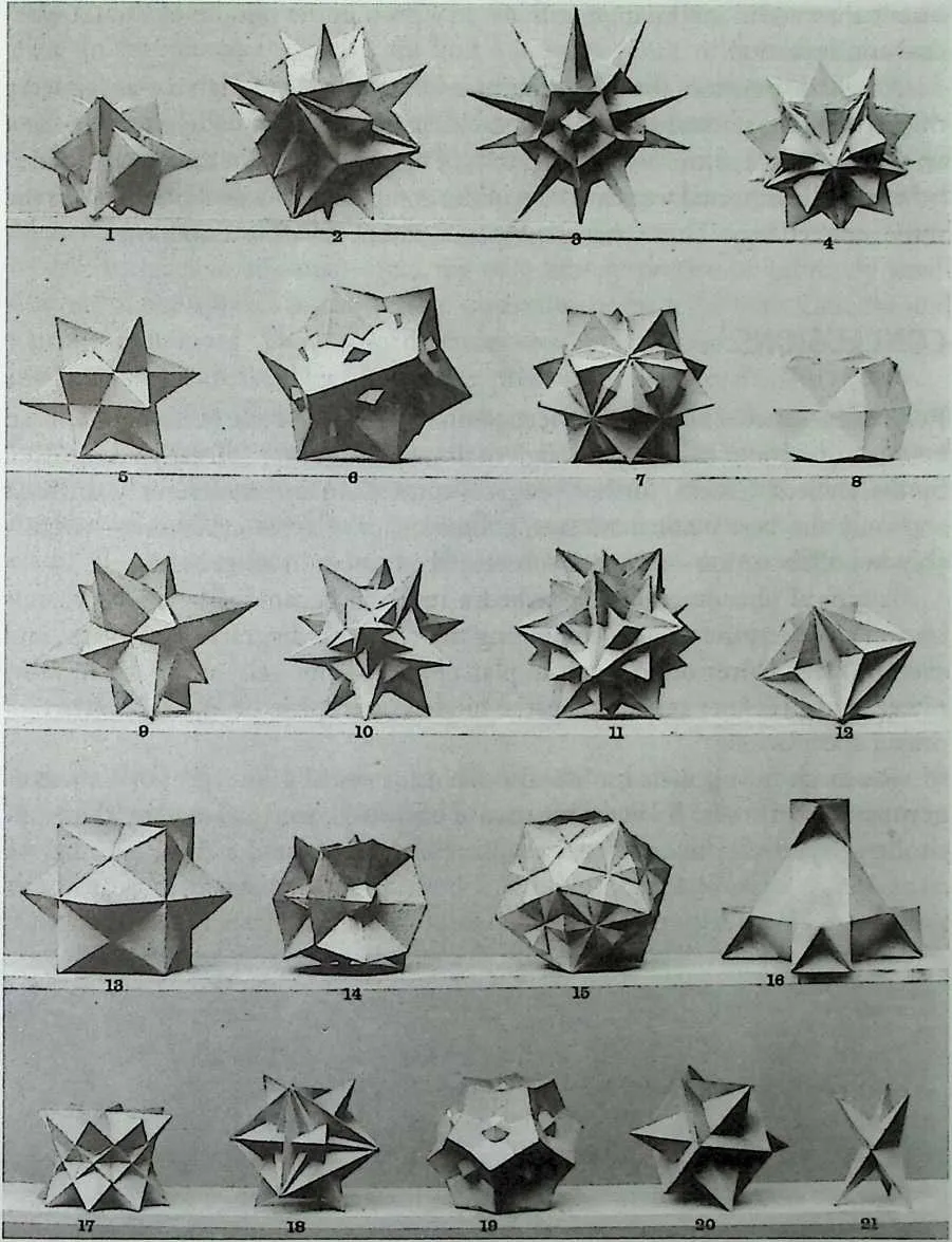
166 Figure 1.27 Paper models of polyhedra variants by Max Bruckner (1900). (Source: M. Bruckner, Vielecke und Vielflache—Theorie und Geschichte, Leipzig, 1900.)
167 pose details had to be such that two or three nodes met in one point. Presumably, this problem was geometrically solved by reserving modular zones in the node area and specifying the exact node form for each position in the system. Even the conventional stairway was integrated into the tetrahedral logic by shaping it as a triangular prismatic frame in one of the legs.50
168 The tower was erected in only 10 days by unskilled laborers. In order to manage it with the least effort, two tower legs and the platform were assembled on the ground, using the third leg—by assembling it in sections—as a jack for the whole structure. Dining the building process, in which the legs—owing to their almost horizontal starting position—behaved as beams, Bell installed an additional triangular frame as a prop in the middle of the tetrahedral configuration.
169 For static purposes the three continuous border rods of each tower leg were thicker than the normal rods.50 It is notable that, at the point where the legs met on the hexagonal platform, Bell used rods of normal section in the borders, surely because he expected weaker forces in the compact platform frame than in the three inclined legs. Thus a remarkably transparent tower was obtained.
2.21 CONCLUSIONS
171Polyhedra—spatial bodies of perfect geometric shape—have fascinated human beings throughout history. Although their major laws were already recognized by the ancient Greeks, further progress turned out to be extremely difficult and only the best mathematicians, geometers, and artist-craftsmen—preferably in collaboration—achieved substantial advances in knowledge.
172 A typical phenomenon of polyhedra research became the ‘‘mixed visualization’’ of scientific results, combining the text with diagrams, drawings, and even models. Durer offered cutout plans for paper models, and Pacioli, Jam-nitzer, and Bruckner relied on spatial models as empiric proof and control of drawn speculations.
173 Research into polyhedra has also been historically interpreted as a dangerous field of study. Its hermetic nature expressed, for instance, by the multitude of symmetry axes in each regular polyhedron or the finite number of
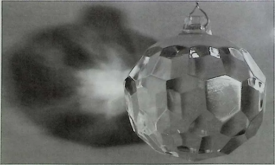
175 Figure 1.28 Polyhedral chandelier piece, ground from a glass sphere (Belgium, 19th century). (Source: Institut fur leichte Flachentragwerke (IL), Stuttgart University. Photo: Gabriela Heim, Stuttgart.)
176 only five regular polyhedra, made the field a source of metaphysical speculation. In Jamnitzer, the artist, we find a positive result of this kind of metaphysics, rendered harmless through joyful humor and presented with considerable artistry. In Kepler’s fate we find a sadder outcome.
177 However, in most cases, history demonstrates the creative potential of consistent polyhedra research. A special result is their role in the development of turning wood and ivory. The mathematical understanding of ‘‘infinity’’ had its counterpart in the manufacturing of infinitely precise or infinitely small objects. Ivory sphere-in-the-sphere objects were made in both Chinese and European cultures. The beauty of these—void of any substantial usefulness—made them an ideal subject for testing precision in handicraft.
178 Leonardo da Vinci invented lattice structures based on polyhedral forms. Their brief history ends around 1900 with the tetrahedron-based space frame of Alexander Graham Bell, which shows a concise understanding and an original use of polyhedra. Bell’s approach may be seen as the legacy of all those persons who, in the past, have been drawn affectionately toward polyhedra.
2.22 METHODOLOGY
180A remark on the methodology and the specific goal of this chapter may be appropriate. In February 1993, J. Francois Gabriel wrote to the Stuttgart Institut fiir leichte Flachentragwerke (IL), asking if somebody could work on the history of the science of polyhedra and their applications in architecture. The author accepted such a vast undertaking, encouraged by his experience with similar studies on the history of geometry (ruled surface structures by Suchov, Gaudf, and Candela and late-Gothic vault geometry). A basic research approach was discussed and it was agreed that the study would focus on the time before 1900, as there is little scientific research and documentation available from this time period. In order to find connections between the use of polyhedra in science and architecture, the author was forced to construct a hypothetical historic path, as only in a few cases are polyhedra instantly recognizable in old architecture. The main stress was given to the technical aspects of the visualization of polyhedra and of the making of polyhedral models, often related to the arts. Because of this technical viewpoint, however, decorative aspects from the international art-nouveau style (Berlage and Gaudi) were not relevant, as was the case with Haeckel’s interpretation of biological specimens (radiolaria) as polyhedral shapes.51
181 My research methodology had to focus on isolated historic examples that—favored by luck—could be traced during continuous investigations in museums or literature. Thus the result is quite fragmentary. In some cases, like the early use of the cuboctahedron shape or the Chinese concentric ivories, the craftsmen may not even have known they were working with a polyhedron. To the author these examples still seem valuable because a polyhedron is not only qualified as some geometric shape or material object, as such, but also by the structure of its axes with its specific technical implications.
182 Because of this research approach, giving priority to the visual aspects of the polyhedron, the science of polyhedral geometry was not dealt with systematically. Although the author tried to establish a chronology of mathematical inventions, this goal could only be reached very superficially.
183 The illustrations were chosen with care but they serve different goals. Some were chosen because they show a plentitude of beauty and can be regarded as symbols of the equal emphasis on art and science. Others illustrate complex geometrical relationships, necessary because they are still ill documented. Finally, some illustrations are informative about the cultural setting of an artist or architect. The first results of my studies on polyhedra history were presented at the seminar Application of Structural Morphology to Architecture in Stuttgart.52
2.23 ACKNOWLEDGMENTS
185Many people were helpful in finding polyhedral examples and the material gathered substantially exceeds that presented here. I want to thank all the people and institutions that provided information, especially the editor Jean-Frangois Gabriel, who took the initiative for this historical survey. Next to him my referees Rowland J. Mainstone and Pieter Huybers took greatest care in strengthening the meaning and beauty of this chapter on such a demanding subject matter, for which I am grateful. Furthermore, I would like to thank Rainer Graefe, Jurgen Hennicke, Frieder Klenk, Werner Muller, Martin Trautz, and Ture Wester for supplying valuable information.
186 The city of Niirnberg—which historically has played a prominent role in polyhedral research and related art—opened its archives; special thanks goes to Dr. Slenczka, the library director, and Dr. Locher, the painting gallery director of the Germanisches Nationalmuseum. Similarly important was a visit to the Griine Gewdlbe museum of the Staatliche Kunstsammlungen, Dresden, where Christine Wendt kindly showed me recent restoration work by the Erbach ivory museum. Other material was found in the Landesmuse-um Baden-Wurttemberg and the Wurttembergische Landesbibliothek, both in Stuttgart. Much literature was checked in the library of the mathematical faculty (Air. Denninger) of Stuttgart University. Thanks also goes to Dr. Lepie, the director of the department of goldsmith art (Aachen Cathedral), who provided detailed information about her forthcoming restoration of the Barbarossa Chandelier in Aachen.
187 I would like to thank the following collaborators who were instrumental during the preparatory studies at the Institut fur leichte Flachentragwerke of Stuttgart University, which is directed by Prof. Werner Sobek: Elisabeth Trautz-Fiilop (archives), Gabriela Heim (photographs and reproduction), and Brigitte Trappe. The original English manuscript text was edited by Frieda Piersma-Spanjersberg.
2.24 NOTES
- 1.
- J. M. Montesinos, Classical Tessellations and Three Manifolds, Heidelberg, 1987.
- 2.
- A. Fischer, Afrika im Schmuck, Cologne, 1991.
- 3.
- W. Menghin, Gotische und langobardische Funde aus Italien, Germanisches Nationalmuseum, Niirnberg, 1993.
- 4.
- R. Christlein, Die Alamannen: Archdologie eines lebendigen Volkes, Aalen, Stuttgart, 1991.
- 5.
- M. Bruckner, Vielecke und Vielflache—Theorie und Geschichte, Leipzig, 1900.
- 6.
- D. J. Struik, Geschiedenis van de iviskunde, Amsterdam, 1980.
- 7.
- H. Gericke, Mathematik in antike und Orient—Mathematik im Abendland, Wiesbaden, 1993.
- 8.
- Fra L. Pacioli, Divina Proportione, Die Lehre vom Goldenen Schmitt, nach der venezianischen Ausgabe vomjahre 1509, C. Winterberg, ed., Vienna, 1889.
- 9.
- A. Sabra, ‘‘The Exact Sciences,’’ in The Genius of Arab Civilization—Source of Renaissance, Oxford, 1978.
- 10.
- B. Lamy, Les Elemens de Geometric ou de la Mesure de Petendtie; qui comprennent les elemens d'Euclide;…, Paris, 1731.
- 11.
- M. Folkerts, E. Knobloch, and K. Reich, Mass, Zahl, und Gewicht, Mathematik als Schlussel zu Weltuerstandnis und Weltbeherrschung, Herzog August Bibliothek, Wolfenbiittel, 1989.
- 12.
- J. Rondelet, Traite theorique etpratique de Part de batir, Paris, 1812–1817.
- 13.
- F. Richter, Die Asthetik geometrischer Kiirper in der Renaissance, Stuttgart, 1995.
- 14.
- J. Malkevitch, ‘‘Milestones in the History of Polyhedra,’’ in Shaping Space—A Polyhedral Approach, M. Senechai and G. Fleck, eds., Boston, Basel, 1988, pp. 80–92.
- 15.
- H. Lepie, ‘‘Radleuchter mit 16 Tiirmen im Karlsdom,’’ in Kirch enzeitung fur das Bistum Aachen, Jan. 1992, pp. 24–29.
- 16.
- Die Kunstdenkmaler der Stadt Aachen, I. Das Munster zu Aachen, Dusseldorf, 1916, pp.138–140.
- 17.
- S. Hunke, Allahs Sonne uber dem Abendland: unser arabisches Erbe, Stuttgart, 1960.
- 18.
- K. Critchlow, Islamic Patterns, an Analytical and Cosmological Approach, London, 1976.
- 19.
- B. Burroughs, ed., Vasari's Lives of the Artists, New York, 1946.
- 20.
- F. Borsi and S. Borsi, Paolo Uccello, Florenz zwischen Gotik und Renaissance, Belser Verlag, Stuttgart, Zurich, 1993.
- 21.
- K. H. Veltman, Studies on Leonardo da Vinci, I, Linear Perspective and the Visual Dimensions of Science and Art, Munich, 1986.
- 22.
- J. Bohm and E. Quaisser, Schonheit und Harmonie geometrischer Former, Berlin, 1991.
- 23.
- A. Angelini, Piero della Francesca, Florence, 1985.
- 24.
- L. Olschki, Geschichte der neusprachlichen Literatur, ersterBand, Heidelberg, 1918.
- 25.
- Petrus Pictor Burgensis, De prospectiva pingendi, [Ozz the Perspective of Painting by Piero della Francesca from the codex of the royal library in Parma, translated into German by C. Winterberg], Strasbourg, 1899.
- 26.
- H. A. Millon, in The Renaissance from Brunelleschi to Michelangelo—The Representation of Architecture, V Magnago Lampugnani, ed., Milan, 1994.
- 27.
- R. Mainstone, Develop?nents in Structural Form, Cambridge, MA, 1975.
- 28.
- M. Cianchi, Die Maschinen Leonardo da Vincis, Florence, 1984.
- 29.
- C. Pedretti, Leonardo Architect, London, 1986.
- 30.
- Albrecht Dilrer 1471–1971, Germanisches Nationalmuseum, Niirnberg, Munich, 1971.
- 31.
- Albrecht Dilrer aux Pays-Bas, son voyage (1520–1521), son influence, Palais des Beaux-Arts, Brussels, 1977.
- 32.
- A. Diirer, Unterweisung der Messung, Niirnberg, 1525; Verlag Dr. Alfonse Uhl, Nordlingen, 1983.
- 33.
- P. Jesberg, Vom Bauen zivischen Gesetz and Freiheit, Braunschweig, Wiesbaden,
1911987.
- 34.
- J. Sellenriek, Zirkel und Lineal, Munich, 1987.
- 35.
- W. Jamnitzer, Perspectiva corporum regularium, A. Flocon (Preface), Niirnberg, 1568, Madrid, 1993.
- 36.
- P. May, ‘‘Die Kunstfertigkeit der Perspektive zu Niirnberg,’’ in Wenzel Jamnitzer und die Niirnberger Goldschmiedekunst 1500–1700, Germanisches Nationalmuseum, Niirnberg, 1985, pp. 161–165.
- 37.
- W. Miiller, Kunstwerk, Kunstgeschichte und Computer, Munich, 1987.
- 38.
- O. PatzeXt,Faszination des Scheins, 500Jahre Geschichte der Perspektive, Berlin, 1991.
- 39.
- J. Kepler, Die Weltharmonik, translated into German and introduced by M. Caspar, Munich, 1990.
- 40.
- D. J. Struick, ed., The Principal Works of Simon Stevin, Volume II, Mathematics, Amsterdam, 1958.
- 41.
- P. Huybers, ‘‘De geometric van uniforme polyeders,’’ Technische Hogeschool Delft, Stevin Rapport 10–76–1, March 1976.
- 42.
- E. v. Phillippovich, Elfenbein, Munich, 1982.
- 43.
- H. Knoppe, Meistertechniken de?’ Drechslerkunst, Original title: Drechslerkunst—Meistertechniken alter iind netier Zeit, Leipzig, 1926, Hannover, 1986.
- 44.
- Wiedergeroonnen—Elfenbein Kunststucke aus Dresden—Eine Sammlung des Griinen Gewdlbes, Deutsches Elfenbein Museum, Erbach, 1995.
- 45.
- J. G. Doppelmayr, Historische Nachricht von den Niiiiibergischen Mathe?naticis und Kunstlern,…, Niirnberg, 1730.
- 46.
- L. A. de Boger and H. Batterson-Boger, The Dictiona?y of Antiques and the Decorative Aits, New York, 1967.
- 47.
- E. Bassani and W. B. Fagg, Africa and the Renaissance—Ait in Ivory, New York,
193 1988.
- 48.
- Schiitze Chinas aus Museen der DDR, Roemer-und Pelizaeus-Museum, Hildesheim, 1990.
- 49.
- K. Andersen, Brook Taylor's Work on Linear Perspective, New York, 1992.
- 50.
- K. Wachsmann, Wendepunkt im Bauen, Wiesbaden, 1959.
- 51.
- K. Bach a.o., ‘‘Radiolarien,’’ Mitteilungen des Institut filr leichte Fliichentragwerke, Vol. 33, Stuttgart, 1990.
- 52.
- J. Tomlow, ‘‘A Bouquet of Polyhedra—Some Remarks on the Image and Significance of Polyhedra in History,’’ in: Proceedings 2. Int. Seminar: Application of Structural Morphology to Architecture, Stuttgart, October 8/9, 1994.
196 Polyhedrality in the Architecture
197 of Brace Goff
198 Rollie Ristine
2.25 INTRODUCTION
200Bruce Goff (190A-1982),1 architect, painter, educator, and composer,2 created in over six decades of architectural practice, primarily in the Midwest, an impressive array of buildings and designs exhibiting an extraordinary profusion of geometric forms—polyhedral, spherical, cylindrical, conical, toroidal, helicoidal.3 Much of his work also contains less easily defined configurations.4 This chapter examines only that family of forms in Goff’s work directly related to polyhedra.
201 We will first define polyhedra and discuss their geometric and nongeometric attributes, including historical, psychological, and symbolic aspects. We will speculate on why Goff used polyhedra in his work and mention some of his architectural influences. Comments are included from Herb Greene on 20th-century thinking about geometry as related to Goff’s use of geometry. We will touch on formalism and the difficulties of description of polyhedra. A taxonomic framework is proposed involving four stages of polyhedrality in Goff’s work. Finally, salient polyhedral aspects of selected buildings are illustrated and discussed with observations from several who have lived in or worked on those buildings.
202 Definition of Polyhedra
203 A polyhedron is a solid bounded by plane faces. A ‘‘regular’’ polyhedron is arranged according to a system of symmetries. The boxlike spaces comprising the bulk of the world’s architecture, from tract house to international style office building, are a special class of polyhedra—rectangular parallelepipeds, or rectangular prisms; that is, spaces bounded by pairs of parallel rectangles at right angles to one another. They occur in Goff’s work as well, but are mentioned in this chapter mainly as a takeoff point.
204 Regular Polyhedra
205 Regular polyhedra include the five well-known Platonic solids—the cube, tetrahedron, octahedron, icosahedron, and dodecahedron—with their simple, powerful, and all-encompassing symmetries, and the thirteen less familiar Archimedean solids, that is, truncated versions of the Platonics, and others such as the cuboctahedron and icosidodecahedron.5 Geodesic domes are an outgrowth of these family members.
206 Further Classes of Polyhedra
207 Other branches of the polyhedra family include extrusions (prisms), pyramids, dipyramids, truncations (e.g., a frustum, or pyramid with its top cut off), skewed and elongated volumes, and so on. Still other variations are evident in specialized fields such as crystallography, which identifies by shape, among many other factors, the several thousand of earth’s naturally occurring minerals, for example, quartz and feldspar.6 ‘‘The mineral world expresses pure volumetric geometry with the greatest clarity, but it is important to remember that these solids do not exist in nature. In their perfect form they exist only on a metaphysical plane, as pure, creative ideation, and can be represented, for the mind to grasp, only through geometry.’’7 Pure, complete, and intact polyhedra belong, in various conceptual garb, to the world of mathematics. Geometric space, a rigorously well defined set of symbols and abstractions, is different from architectural space, which is not usually so well defined or so abstract—and yet the two are intimately related.
208 Why Polyhedra?
209 Being an architect and not a geometer, why did Goff employ polyhedra—since a major portion of his oeuvre might be called ‘‘beyond the polyhedron’’? Probably the most compelling reason, in terms of childhood development, is that ‘‘Goff’s father was a jeweler and gave the boy crystals to play with. Pyrites, crystalline rocks, and semi-precious stones are to be found all over the American southwest.’’8
210 Mental Tools
211 There may be a universal appeal in polyhedra that Goff felt in common with many other architects. The abstractions, definitions, and symbols of the world of solid geometry are among the essential mental tools required for the invention, discovery, and modeling of space in the real world. One of the major means of delimiting and enclosing space and creating volumes is by the use of planes (another is through the use of curved surfaces). Polyhedra provide a rich source for the interrelation of planes and Goff has drawn on that stock. As Goff said, ‘‘Some people open doors and others walk through them.’’
212 Imperfect Polyhedra
213 In architecture, spaces are enclosed or defined by fragments, repetitions, distortions, proliferations, and other variations of geometric solids (like the polyhedra examined in this chapter) realized in ‘‘concrete’’ form. Just as in biological forms ‘‘…the geometry’’ says mathematician H.S.M. Coxeter, ‘‘…developed to perfection by our soap-films in the twinkling of an eye, is only roughly developed in an organic structure, even one so delicate as elderpith; the conditions are no longer simple, for friction, viscosity and solidification have vastly complicated the case.’’9 In every example of Goffs architecture, where simple, pure, idealized geometric form is involved—there are functional, spatial, and circulational, that is to say, organic, elements that modify, develop, anchor, and objectify that ideal. In spite of his respect for Wright’s ‘‘organicity,’’ Goff suggested taking the ‘‘nature of materials’’ with a grain of salt. Rigorous intellectual and philosophical purity in architectural realization can be self-defeating. Architectural solutions require unparallel (epiped?) coordination of large arrays and tangled hierarchies of conditions, levels, elements, and evaluations—so it is not surprising that one does not often find complete and pure expression of Platonic and Archimedean polyhedra in architecture.
214 Historical Position of Polyhedra
215 A brief glance at architectural history will find Goff, along with a number of other 19th-and 20th-century architects, for example, Antonio Gaudi, R. Buckminster Fuller, and Frank Lloyd Wright, to mention just several, creating at the growing tip of an evolution of ever more complex spatial ‘‘conceptioning’’ (to use a Fullerism).
216 Architecture as metaphor could probably be applied as far back as the big bang, but we will not go quite that far. Animal architecture is free, curved, rough, organic10—examples of more or less perfectly straight lines and flat planes are rare as, say, a spider hanging from a strand of its own silk in a still cave or the planes in a honeycomb. Straight line and plane are more apt to be approximated in natural inorganic forms—the surface of a pool of perfectly still water, a fine icicle, a patch of glare ice, but especially in minerals, for example, an iron pyrite cube.
217 Geometry is a human endeavor that brings the straight line and plane to building, whence in architecture the rectangular parallelepiped rears its ubiquitous head—the cube, the box. To protect the box, the traditional pitched roof appears—enclosing a triangular prism of space.11 The tent appears as a variation of pyramid, frustum, prism, or cone. An early basic geometric solid was the Egyptian pyramid—a mass, not spatial. The pyramid’s developmental precursor was the frustum, or mastaba. Both are polyhedra in the general sense, but they are not regular polyhedra. Nonpolyhedral forms were exemplified in structures from the domes (hemispheres) of the igloo to Greco-Roman stonework, in the cones of the Plains Indians’ tepees, variations on intersections of half-cylinders in vaulting throughout the ages, full cylinders in masonry towers, warped surfaces and solids generated by rotation about axes in African paraboloids, the Islamic dome on top of a cube, and so on.12
218 Goff’s Work in the Context of the history of Architectural Geometry
219 Goff’s architectural forms take their place in the historical evolution of an ever more subtle, complex, and sophisticated knowledge and use of geometry. This is not to say that architectural work in the past did not have its mind-boggling intricacies, for example, Gothic masonry, Japanese joinery, Islamic ornament13 as well as the subtleties of proportional systems such as the ancient Greek orders.
220 I mention architectural influences on Goff in spite of Ben Allan Park’s daunting challenge: ‘‘It is useless to consider Goff’s influences. He has a much wider appreciation of the work of his contemporaries than might be supposed.’’14
221 Claude Bragdon’s early-20th-century books on the generation of geometric forms were well known to Goff. When Projective Ornament by Bragdon was published in 1915, Goff would have been 13 years old—22 when Bragdon’s The Frozen Fountain was published in 1924.
222 Furness, the Vienna Secessionists, Finsterlin, Mendelsohn, and other late-19th-and early-20th-century spatial innovators and geometers were among Goff’s interests and exemplified the subject matter of his modern architectural history courses, which he taught at the University of Oklahoma.
223 Goff was not only a dedicated ‘‘student’’ of Wright’s work (although never an apprentice) but also a friend. Other influences, to mention just a few, were Sullivan, art nouveau, Islamic, Balinese, Japanese—in short, the expanse of world architecture.
225226In Goff’s own words:
227I prefer Paestum to the Parthenon …it’s more vigorous. I admire almost all Hindu temples …Madras …Fatehpur-Sikri…the Japanese works, of course …the Ise Shrines. I love the detachment of the Katsura Palace, the Imperial Coronation Hall in Kyoto and the palaces there …the Golden Pagoda. In China, the Temple of Heaven in Peking …the whole Peking complex. …I have so many favorites…the Gothic at Cologne and Rheims. I like Scandinavian wood architecture …pre-Columbian …the Monadnock building and others in Chicago …Sullivan’s banks. I admire lots of buildings that are not supposed to be architecture: the hut houses of Samoa, African huts. …Wright, the Heber master …and the greatest of them all, Gaudf. A completely dedicated man.15
228 Goff’s complex use of geometry with its triangulated precursors to geodesics, its paraboloidal reinterpretations of organic lines of structure and growth predates but is unsurpassed in inspiration by 20th-century developments.
229 To try to show how specific Goffian forms were derived from such historical osmosis is perhaps part of the ‘‘uselessness’’ that Park is implying. Goff’s output should be regarded as an original and consistent unity, informed by and part of global architecture—in spite of the apparent differences between his varied projects. Here we are spotlighting only that fraction of Goff’s output that utilized a spectrum of polyhedral prototypes.
230 Geometry—Theoretical Versus Applied
231 The practical application of geometric forms in architecture may lag considerably behind the development of new mathematical concepts, but architectural composition has its own distinct systems of organization—albeit often related to spatial configurations: from circulation networks, functional hierarchies, environmental interfaces, and microclimate control to configurations affected by the strength of materials, safety, security, and ease of use.
232 Practical Necessity of a Conceptual Framework
233 In order to build, such function complexes must be integrated into spatial configurations. This is where the intimate working sense of sohd geometric forms comes into play—as the conceptual grid for the organizational/functional entities. Years of experience permit a designer to coordinate, to marry the substance, skeleton, and skin with appropriate forms through novelty and inspiration—to create.
234 Crystallization of an Idea
235 From these systems of architectural organization several functional vectors might provide the germ of an idea, which would act as a catalyst to produce a polyhedral concept, just as—when in a chemical bath—at a certain temperature and pressure an initial prod produces a rapidly spreading crystallization, unique for those specific conditions.
236 Goff and Computers?
237 Goff’s polyhedral designs, accomplished just before the advent of computers, would have been facilitated and perhaps made more complex had he used computers. The ‘‘human biocomputer’’16 was already there—the brain; however, we will speculate that Goff would have used the computer to further the unity of the arts with architecture. A computer could be used, for example, to replicate metaphorically the shapes derived from Trois Morceaux en Forme de Poire—the music of the ‘‘spheres’’ as embodied in a pear by Erik Satie (another Goff favorite), who was in turn alluding to painting. We are reminded of Philip Johnson’s designing by carving up a pear, the resultant shapes of which were to have been digitized in Frank Gehry’s (French developed) Catia computer program for a joint venture.17
238 Computer usage, logic, and mathematics have much in common with music. Goff had a wide-ranging interest in music, especially that of the 20th century. One of his favorites was Claude Debussy whose L’Apres Midi dhm Faun was illustrated by Goff in a painting for Joe Price’s Studio. (The painting is reproduced in Architectural Design Profiles 16.) Goff felt a strong kinship between music and architecture and invited his students to regular listening sessions from his extensive record collection. To teach design, Goff used musical principles such as theme, variation, development, rhythm, and counterpoint, specifying their direct analogs to visual and spatial elements in architecture.
239 In any case, students and designers who utilize the computer today will be better situated to assimilate, certainly to manipulate, complex polyhedral and other geometries. Among the problems that might be expected in using polyhedral forms, for which computers will prove useful, are: conceiving, visualizing, grouping, drawing orthographically and in perspective, linear and volumetric measuring, dealing with nonparallel planes, marking, and aligning. In construction the computer facilitates stereolithography—layout, fitting, joining, and cutting. Walking tours through computer-animation perspectives are becoming more accessible.18 However, as the electronically aided visual representation of more and more complex forms becomes easier—so their verbal description becomes more difficult but perhaps more important—essential to the linkage of the visual/emotional world with the moral/historical perspective.
240 Herb Greene on 20th-Century Thinking About Geometry and Goff’s Use of Geometry
241 Berkeley architect, painter, author, educator, and Goff student Herb Greene, discusses the mystique of geometry in architectural thinking among the European rationalists early in this century contrasted with the position that geometry occupied in Goff’s work:
243244In the Nineteen Twenties when the functional, mechanical and technological revolution in architecture was replacing historical eclecticism, the rationalists began to use geometry with conscious intent to create architectural forms denoting function, machine technology and an image cleansed of historical associations. The geometry selected by the rationalists, however, drew heavily on a narrow range of Euclidean forms. The rationalists unconsciously inherited the classical belief that value can reside in explicit forms. The faith expressed by le Corbusier in the flat plane, cube and cylinder characterized much of the spirit of the times. The Euclidean forms were conceived as embodying ultimate simplifications of nature. Exceptions and overlaps were sometimes to be found in the works of the leading rationalists, but the rectangular flat plane tended to become a symbol eliciting a response to function, technology and a feeling for contemporary dynamics. The point is that architects, then as now, tend to regard historical forms, cubes for instance, as possessing in themselves the subjective values that only mankind can project into forms. That familiar forms in the environment are of vital importance to human psychological experience is not questioned; what is questioned is the belief that certain forms, such as Euclidean forms, possess immutable value and are to be imposed on the architectural design situation. Mies van der Rohe was probably the apotheosis of the modem acceptance of this belief.
245Bruce Goff has been cautious of using geometry, or any other ‘‘tool’’ of architecture, to express a predetermined type of perfection to be applied wholesale to a variety of architectural programs. Architecture, rather than assuming a geometry sanctified by familiarity and unconscious psychological associations, should evolve its geometry by responding more intimately to conditions in the immediate design situation. For Goff, the final design form must show evidence of being derived from a multifarious world. There are the particular conditions of the site, climate and context, the life experiences of the client or user, the building program, the limitations of materials and construction techniques, and there are the notions of order and art influenced by the life experiences of the architect. Goff does not pay lip service to these ideas. It is his belief that a wholehearted attention to these factors is required, and that it can only produce a unique solution to every design situation. He maintains that the architect is both obligated and free to use whatever form that is suggested by a determinedly open-minded examination of the problem….
246…the variety of new geometric forms appearing in the architecture of recent years should be mentioned. The best of these have been derived from structural and technological sources: shells, space frames, air forms and others. Goff, in addition to using structural determinants, has, since the early forties, been deriving his unique shapes from cultural, social, esthetic, perceptual and psychological determinants. There is a difference in intention as well as in results.19
247 Preconscious Meaning in Polyhedra?
248 To overlay Greene’s ‘‘structural…perceptual and psychological determinants’’ with a reconsideration of formal determinants, we ask whether the nodes of precision in three-dimensional geometry and the symmetry in regular polyhedra resonate in our mind with some as yet undiscovered inherent preconscious intensity? Is there a structure within our inherited neural network that corresponds to such three-dimensional geometries? Perhaps something of this ilk will be discovered among the multidimensional ‘‘point sets’’ that comprise the brain’s universe of synapses.
249 Psychological Effects and Symbolic Aspects of Polyhedra
250 According to the philosopher Suzanne K. Langer, ‘‘Symbolic expression is something miles removed from provident planning or good arrangement. It does not suggest things to do, but embodies the feeling, the rhythm, the passion or sobriety, frivolity or fear with which any things at all are done. That is the image of life which is created in buildings; it is the visible semblance of an ‘ethnic domain,’ the symbol of humanity to be found in the strength and interplay of forms.’’20 The affective properties of polyhedra impart a palpable spatial feeling. This is due both to their multiple three-dimensional symmetries and to their contrast to conventional ‘‘extruded’’ architectural space, to which most of us have been acclimated. Goff pointed out that the acute angle, for example, could represent anger, whereas the obtuse angle has a more relaxed feeling and the circle is more intuitive. As visual symbols polyhedra grab and hold attention. Polyhedra are jointed, three-dimensional, straight-line abstractions of the structure of tree branches—the limbs within which the capabilities of human hand and eye coordination evolved and are thus inextricably attuned. They convey a feeling of strength, and, indeed, the triangulated geometry of many polyhedra gives them an inherent structural rigidity. They convey a presence—a sculptural sense of unified containment beyond the overly familiar square and rectangular world of grids. Because of this they must be handled carefully and with knowledge and discipline. The Goff work discussed in this chapter provides examples of such use.
251 Monumentality as an Effect of Polyhedral Usage
252 Monumentality is another ancient phenomenon on the border between illusion and symbolism. Detailing, massing, scale, and texture can be made to work together to create a larger-than-life entity. Polyhedral usage appears to contribute to this effect in Goff’s structures. The term ‘‘monumental’’ is related to the word mountain. There is something symbolic of the mountain in the angular and crystalline forms of polyhedra.
253 Golden Mean Ratio
254 The golden mean ratio, occurring so frequently in nature, is inherent in certain Platonic polyhedra. Le Corbusier, for example, found the ratio and its extension into the Fibonacci series so vital that he wrote two volumes on the subject.21 As far as I know, however, Goff did not exploit this mathematical phenomenon in his designs and the topic will not be pursued here. De Long and others have discussed Goff’s use of magic square proportional systems and the like.
255 Parallelepiped Architectural Spaces
256 The ubiquity of parallelepiped architectural spaces in Western culture makes them invisible, transparent—one is almost oblivious to such spaces. Mies van der Rohe’s ‘‘Less Is More’’ with its rectangular box embodiment would seem to arise from a hostage-like or perhaps, Machiavellian, acquiescence to this convention; however, atop our 21st-century perch we may lose sight of the excesses of cluttered Victoriana from which these minimalist Miesian urges arose. Goff’s approach to spatial experience, on the other hand, is emotional and it is expressed—in other words, brought to one’s attention; meant to be seen, felt, delighted in; made available to the senses. Does this arise out of necessity from the lonely midwestern plains—an emotional crescendo, up from pragmatic subsistence—in contrast to the anhedonic, rationalist cubic formula—a decrescendo from Victoriana. Though affective and emotional, we experience a powerful intellect at work in Goff’s architecture—always striving for an exuberant expression of space.
257 Opposition to ‘‘Formalism’’
258 Marcel Proust’s character, M. De Norpois, complains, ‘‘All those Chinese puzzles of form, all these deliquescent mandarin subtleties seem to me to be quite futile.’’ However, to reject the significance of form, its study, and its conscious application (e.g., formalism?) is to ignore one of the primary elements of the creative process in architecture (or any other art)—the conceptual spatial matrix.
259 Acquaintance with Polyhedra
260 Practical gain aside, world expositions and the increasing use of space structures are familiarizing many with the rudiments of polyhedra in architecture; still, few are practiced in the verbal and visual languages of form necessary for the description of such spaces.
261 Description Difficult
262 Goffs geometric ingenuity makes description difficult. According to former Goff assistant, Larry Wayne Grantham, Goff said, ‘‘There are two reasons for an element of architectural design—the reason one gave the client and the real reason.’’ Still, becoming aware of the language of solid geometry and knowing that some of these forms yield to description and analysis might give some legitimacy to Goffs work for those who are not practiced in the perception of architecture, or for those seeking ‘‘rationale.’’ If one already appreciates his work, another layer of meaning might be added. Grantham says further, ‘‘In my experience with Mr. Goff, when he was from 72 to 76 years of age, I have no recollections of his describing his work using technical descriptions of the forms…. I will concede, though, that Goff knew his work would be analyzed thoroughly. I do not understand that some individuals need such descriptions. The danger, as I believe Goff would have commented, is that people might use such analysis as a means to create formulas for copying. Goff often spoke of things growing from the problems to be solved outward to define the space. Such forms are always unique to each design opportunity.’’
263 Describing Complex Forms
264 Descriptive attempts, however, indicate why visual means are preferable to verbal. With twinnings, abuttings, intersections, interpenetrations, truncations, and so on, the formal descriptions of polyhedra in architecture tend to be overwhelmed by the complexity of spaces—the nomenclature can quickly become unwieldy or superfluous. Goff’s architecture, however, seems to teach itself, nonverbally. The rewards are raised consciousness—greater satisfaction in architectural use—in the appreciation of the play of light and shadow, in an awareness of space. Goff had confidence in the inevitable power and rightness of his work.
265 Four Stages of Polyhedrality
266 Goff’s use of polyhedra can be conveniently, if somewhat arbitrarily, placed in four stages from less to more polyhedrality, as follows: (1) virtual polyhedra, (2) nonregular polyhedra, (3) single-cell regular polyhedra, and (4) multicell regular polyhedra.22
267 These ‘‘stages’’ are not intended to carry an implicit value judgment of the worth or beauty of such forms, for example, that a close-packing arrangement of Stage 4 is somehow better than, say, a simple horizontally extruded prismatic space. Each should be considered according to its purposes and situation.
268 Stage 1: Virtual Polyhedra
269 (Pseudopolyhedra would be too negative a term.) This category sees surface effects ‘‘striving’’ toward polyhedra and depth, but stymied by limits of economics or function. It includes diagonal motifs, beveling, truncation, champfers, ornament, and related nonrectilinear elements occurring within the confines of rectangular boxes. Two-dimensional iterations (i.e., repetitions, rhythms) would be included. Triangular patterns are also used frequently.
270 Some Goff designs have an illusory quality—what might be called ‘‘virtuality’’ (a concept taken to its extreme today by the spread of computer virtual reality)—the semblance of the third dimension upon a two-dimensional surface. If it were not economically feasible to develop a full polyhedral theme for a client, Goff might provide, because his thinking was spatial, a more limited, two-dimensional representation of polyhedra—or, more generally, of ‘‘depth cues’’23 through the manipulation of ornament, fenestration or, say, the beveling or inclining of surfaces such as railings, walls, soffits, mullions, or struts. An impression of depth is thus enhanced in forms and surfaces where it might not otherwise be economically obtainable. There is a hint of art deco here with its geometric surface pattern orientation; however, this stage is more concerned with allusions to depth. The effect is apparent in many Goff designs, for example, the Page Warehouse, Tulsa, Oklahoma, 1927, and the Floral Hills Memorials, Project, 1959. Still, the love of rhythm and pattern for its own sake is obvious in Goff’s work.
271 ‘‘Virtuality’’ is also evident in Frank Lloyd Wright’s use of ornament, especially his leaded glass—with its overlappings, repetitions, and angles—often giving a strong sense of a third dimension not unlike the effect of an isometric drawing. The illusion is made more complex when looking, through such a depth pattern, at the three-dimensional world outside the window.
272 Among examples illustrating this stage are the Hyde and Snyder Houses and the Floral Hills Mortuary complex. In the Blackwell Building, Project, Dallas, Texas, 1961, two three-story-high 45° triangles side to side at a prominent corner act together to imply a tetrahedron.
273 Stage 2: Nonregular Polyhedra
274 (Proto-polyhedrality; proto-Platonic, or proto-Archimedean geometry) This category includes nonvertical extrusions, vertical extrusions of nonrectilinear shapes, polygonal prisms, pyramids, and various sloping surfaces. Extrusion of triangular forms is prevalent.
275 Limitations of Extrusion. Goff discussed with his students the tired limitations of creating space via vertical (gravity generated) extrusion from the floor plan. This concept is expressed in Goff’s work through (1) extrusions along axes other than vertical (e.g., prisms) and (2) nonextruded spaces such as pyramids and frusta.
276 Prisms. Prisms are a recurring theme in Goff’s work, prisms, that is, with nonrectilinear bases—extrusions—but often nonvertical extrusions—very likely terminated by other than simple planes, but if planar, usually at angles other than perpendicular to the direction of extrusion, for example, the horizontal prisms of the Price Studio 2.
278279Prisms as Proto-Polyhedra. To give a polyhedral ‘‘boost’’ to a form, that is, to enhance its three-dimensional character, one could apply similar operations to different dimensional axes—that is, to front and side elevations as well as plan. An extrusion could be terminated (the ends closed) with a shape similar to its base or cross section. Take a rhombic prism, for example. Rather than trimming or closing the ends with flat planes, those ends might be shaped by dihedral angles, acute or obtuse, creating concavities or convexities—or virtual tetrahedra. In the Snyder House, Project, Dewey, Oklahoma, 1958 (Figure 2.1), V-shaped terminations at the ends of the very prominent ‘‘bay windows’’ are virtual tetrahedra, defined by two pairs of opposite edges (Figure 2.2). Variations on this idea appear frequently in Goff’s work.
280Examples of Stage 2 are the Nicol, Bass, and Gutman Houses and the Price Studio (as built).
281Stage 3: Single-Cell Regular Polyhedra
282(Or single-volume polyhedral space) This stage is made up of Platonic and Archimedean solids and their duals and facially subdivided variations (geodesic domes) in single units or separated multiple groupings in which the single polyhedra are still obvious units. This stage might occur in the building as a whole—the Crystal Chapel is a prime example—or in regions or details of a building, for example, the Rudd House projects. Another characteristic might be ‘‘soft packing’’ or ‘‘unpacking’’ (as opposed to ‘‘close packing and hard packing’’). This is simply the repetition of polyhedra without abutting; see the Rudd House discussion.
283Geodesic domes fall into Stage 3. Buckminster Fuller (discussed in Chapter 4) lectured at the University of Oklahoma once or twice when Goff held the architecture department chair in the late 1940s and early 1950s.24 Although Goff’s polyhedra were usually subordinated to a personal architectural gestalt, curiously enough, in the several of Goff’s designs involving patented geodesics the domes’ triangulated configurations remained dominant and essentially unaltered, for example, the Fitzgerald Realty Office Building, Project, Tyler, Texas, 1965; the Le Boeuf House, Project, La Grange, Texas, 1967; and the Harry Goff House, Project, Tulsa, Oklahoma, 1962. Each used, according to De Long, ‘‘…a patented wood version of a geodesic structure …developed by the Pease Company and manufactured by Geodesic Domes Inc., Davidson, Miss. Two diameters were offered: 26 feet and 39 feet. In 1960 these cost $1,300 and $2,600 respectively.’’25 These domes were, polyhedrally speaking, based on the triacontahedron.
284Stage 4: Multicell Regular Polyhedra
285(Cell iteration) Stage 4 comprises clusters of Platonic and Archimedean solids or their duals in space-filling, perhaps close-packing arrangements—the polyhedra abutting, side to side, front to back, and/or up and down—regularly or irregularly. Among the prominent actors seen on Stage 4 are structural space lattices (three-dimensional matrices that owe their inherent
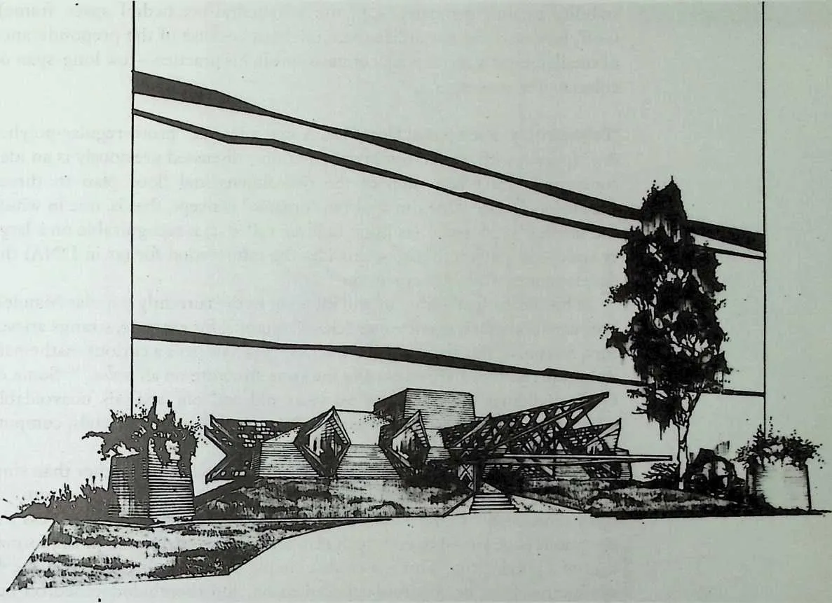
287 Figure 2.1 Russell B. Snyder House, Project, El Dorado, Kansas, 1958. Rendered perspective. (Courtesy of the Ryerson and Burnham Libraries of the Art Institute of Chicago.)
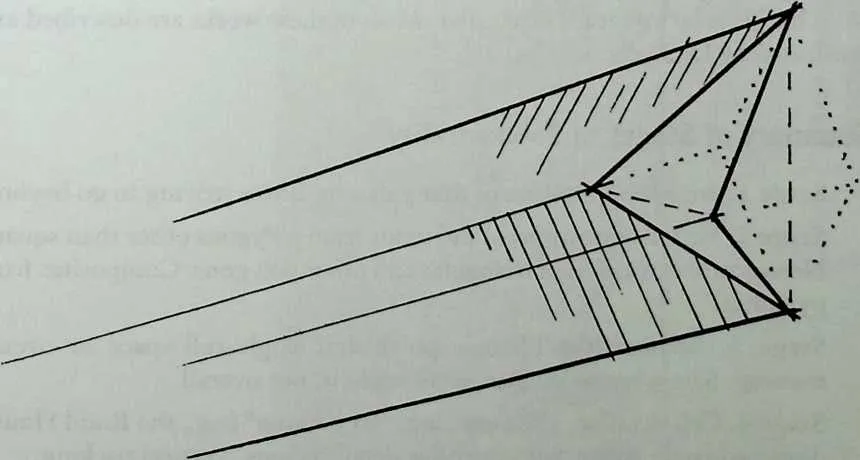
290291Figure 2.2 Snyder House. Virtual tetrahedron.
292 stability to unit geometry, e.g., the tetrahedral/octahedral space frame). Goff, however, did not utilize them, perhaps because of the preponderance of smaller, mostly residential, commissions in his practice—few long-span or column-free spaces.
293 ‘‘Polyhedrizing’’ a Tessellated Floor Plan. A step after the ‘‘proto-regular-polyhe-dra’’ (prisms with certain basal configurations) discussed previously is an idea concerning the relationship of the two-dimensional floor plan to three-dimensional space. One can apply an ‘‘organic’’ concept, that is, one in which the smaller ‘‘seed-germ’’ (as Louis Sullivan called it) is recognizable on a larger scale—or, put another way, provides the information for (as in DNA) the development of a larger organism.
294 This idea is symbolized by and inherent in the currently popular Mandelbrot equation graphics and other ‘‘chaos’’ spinoffs, for example, strange attractors, Sierpinski figures, and other fractals. ‘‘Fractals have a curious mathematical property: they have essentially the same structure on all scales.’’16 Some of Goff’s buildings are now over 50 years old and our analysis unavoidably attempts to superimpose various latter-day concepts such as fractals, computer graphics, deconstruction, and postmodernism.
295 A floor plan composed of polygonal units (tessellations), rather than simply serving as the base for a vertically extruded space, could be taken into the third dimension—into a volume—by using a similar polygon to express the elevations (side views) of each such plan unit, thus contributing to the formation of a polyhedron. This is a crude example that works literally with the 4-symmetry of the octahedron, cuboctahedron, and rhombidodecahedron but would not be sufficient for development of the 5-symmetry icosahedron and dodecahedron. In this way a tessellated plan could serve as the base for a Stage 4 space-filhng polyhedral matrix of which the Wilson and Pollack/Warriner Houses are examples.27
296 Table 2.1 fists stages and polyhedral configurations for representative buildings and projects.
297 This list is by no means exhaustive. Most of these works are described and illustrated by De Long.
298 Summary of Stages of Polyhedrality
300301Stage 1. Surface application of triangulation. Boxes striving to go beyond. Stage 2. Vertical extrusions or pyramids from polygons other than square. Nonvertical extrusions of triangular and other polygons. Composites from pyramids.
302Stage 3. Archimedean/Platonic polyhedral single-cell space or overall massing. Same, but in smaller detail regions, not overall.
303Stage 4. Cell iteration, close-packing, ‘‘far packing’’ (e.g., the Rudd House, discussed later). Same, but in smaller detail regions. Vertical packing.
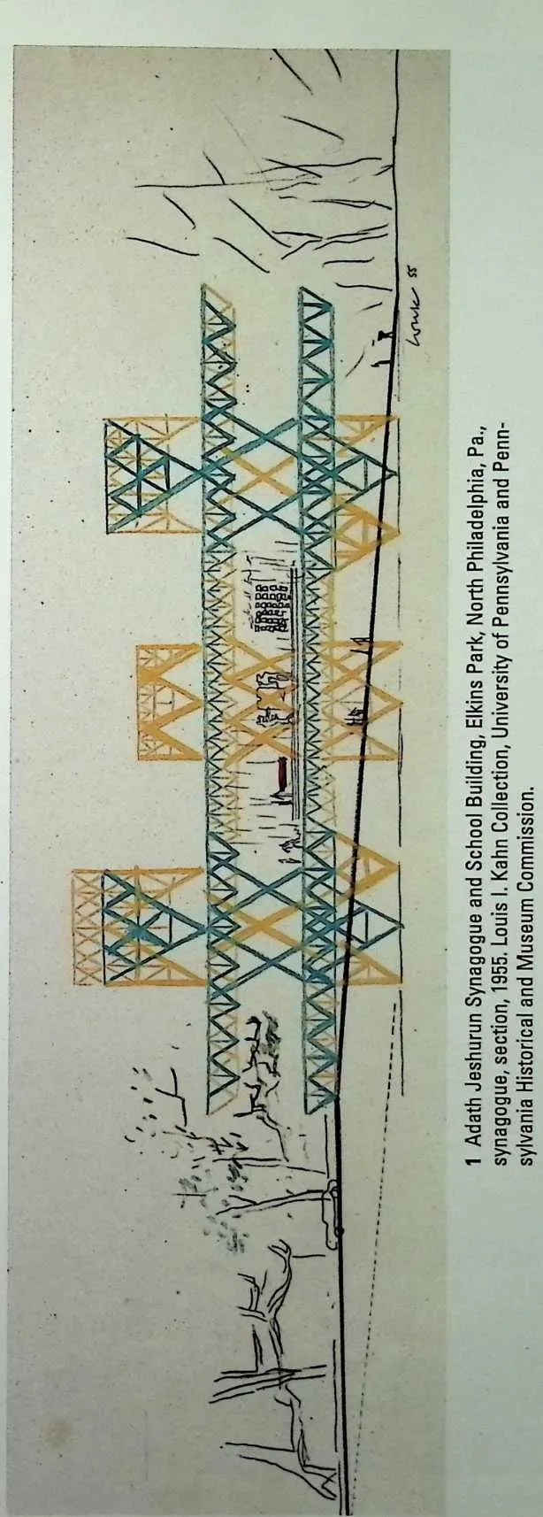
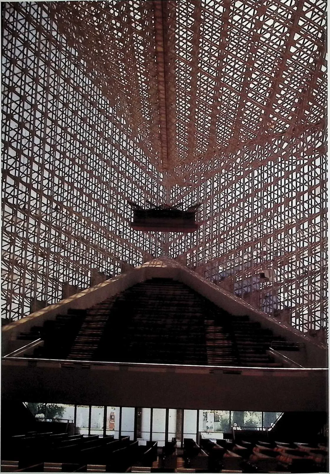
306 2 Interior of balcony, looking east (Photo: J. Francois Gabriel. Reproduced with permission.)
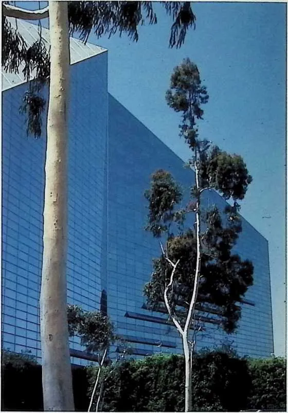
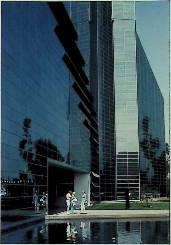
308 3 Exterior framed by eucalyptus trees. (Photo: J. Francois Gabriel. Reproduced with permission.)
309 4 Exterior of northeast entry ventilation louvres and large pulpit doors in closed position. (Photo: J. Frangois Gabriel. Reproduced with permission.)
310 5 Detail of space truss. (Photo: J. Francois Gabriel. Reproduced with permission.)
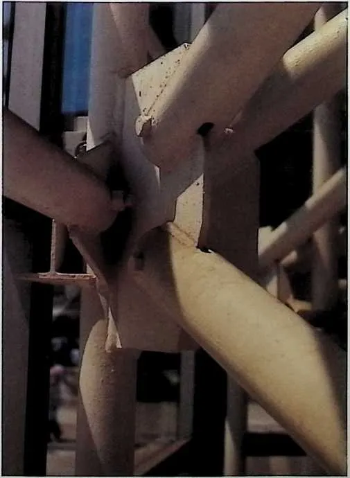

313 6 Four cells of the 16 structures of the family (434) obtained by locating a vertex at every available position within the fundamental region (shown in exploded view). The structures are arranged on the vertices of a four-dimensional cube and indexed accordingly.
314 7 Portions of 16 periodic spacefilling structures corresponding to Color Art 6.
315 8 Cells of 16 structures of family (434) obtained by removing red and green faces from the structures of Color Art 6.
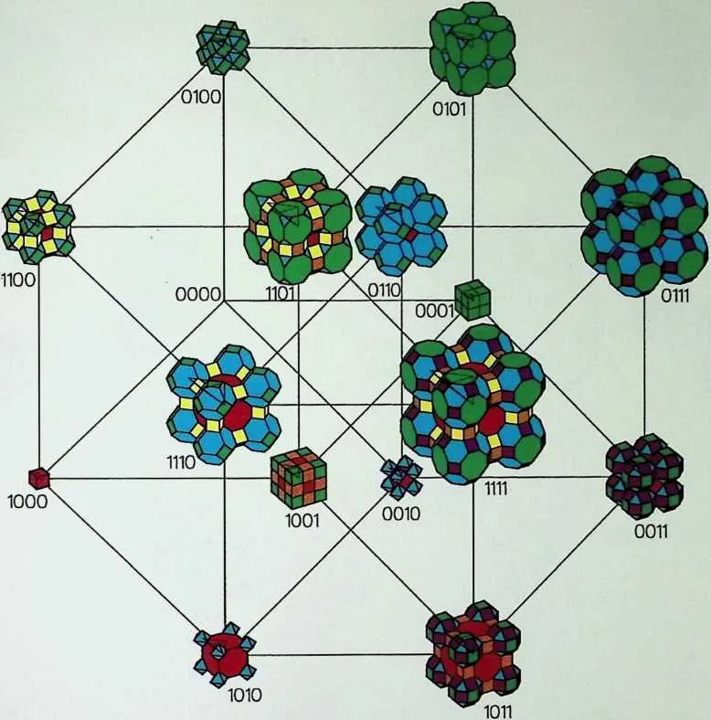
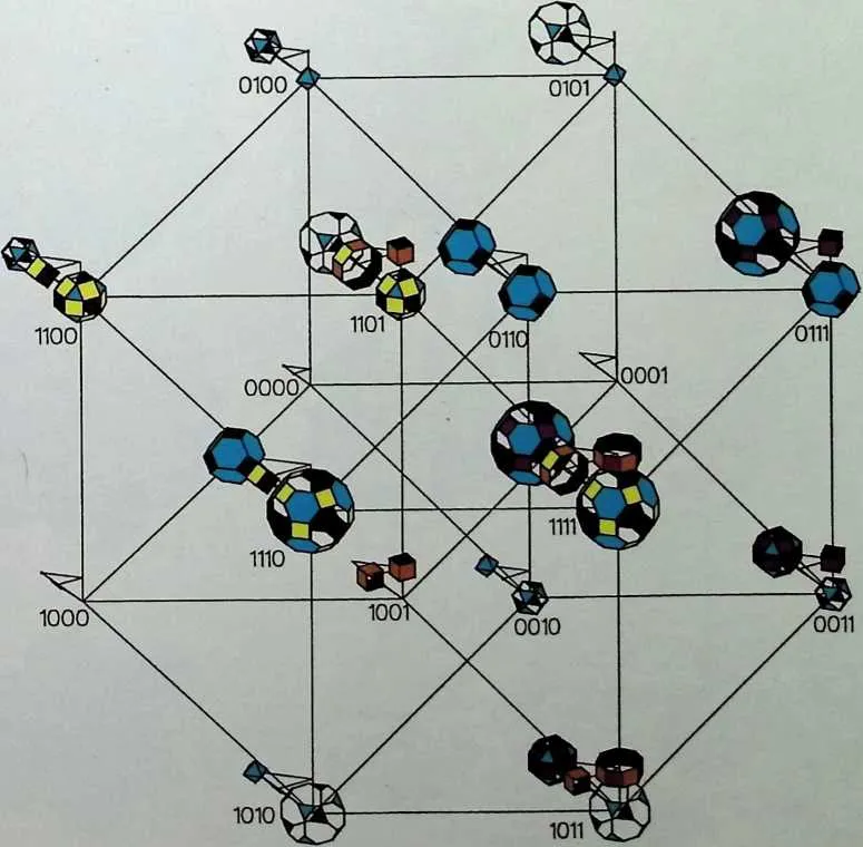
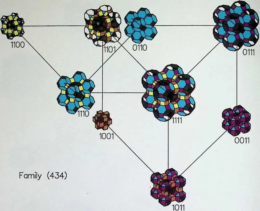

- 9.
- Portions of nine labyrinths of family (434) having red and green faces removed, corresponding to part of Color Art 8.
- 10.
- A two-dimensional lattice of continuous transformations between four different labyrinths of family (434) shown in Color Art 9.
320 1011
- 11.
- Cells of nine labyrinths of family (433) having red and green faces removed (shown in exploded view).
- 12.
- Atwo-dimensional lattice of continuous transformations between four different labyrinths of family (433) shown in Color Art 11.
322 13 Cells of nine labyrinths of family (533) having red and green faces removed (shown in exploded view).
323 1011
324 14 A two-dimensional lattice of continuous transformations between four different labyrinths of family (533) shown in Color Art 13.
326 Summary of Stages of Polyhedrality □ 49
327 TABLE 2.1 Polyhedrality in Goffs Work
|
333Building |
334Stage |
335Polyhedra |
|
336Hyde/Lane House |
3371 |
338Champfers, bevels |
|
339Floral Hills Complex |
3401 |
341Virtual dual transformations |
|
342Ledbetter Cottage |
3431 |
344Virtual pyramid of tension rods intersecting a square prism |
|
345Blackwell Building |
3461 |
347Virtual tetrahedron |
|
348Searing House |
3491,2 |
350Hexagonal prism |
|
351Briar Cottage A |
3521,2 |
353Truncated triangular prism |
|
354Black Bear Motor Lodge |
3551,2 |
356Triangular prism, tetrahedron, stellated tetrahedron |
|
357Phi Beta Delta Fraternity House |
3581,2 |
359Trapezoidal prism, virtual tetrahedron |
|
360Pi Lambda Phi Fraternity House |
3611,2 |
362Triangular prism, half-cuboctahedron |
|
363Phi Sigma Epsilon Fraternity House |
3641,2 |
365Triangularly arrayed rectangular parallelepipeds |
|
366Snyder House |
3671,3 |
368Virtual tetrahedra, window bays |
|
369Unseth House 1, Project |
3702,4 |
371(Quasi) tetrahedra/octahedra space frame |
|
372Unseth House 2 |
3732 |
374Triangular prism |
|
375Nicol House |
3762 |
377Octagonal prisms and pyramid |
|
378Bartman ‘‘Triaero’’ Cottage |
3792 |
380Hexagonal diprism enclosed by a truncated octahedron |
|
381McCullough House |
3822 |
383Dodecagonal prism |
|
384Hopewell Baptist Church |
3852 |
386Multisloped dodecagonal pyramid |
|
387Bass House |
3882 |
389Partially stellated dodecahedra (or intersecting pentagramal pyramids) |
|
390Gutman House |
3912 |
392Truncated triangular dipyramid |
|
393Miller House (porch) |
3942,3 |
395(Undefined—facets somewhat like a cut gem) |
|
396Freeman House (porch) |
3972,3 |
398Pyramid and inverted frustum |
|
399Price Studio 1 |
4003 |
401Interpenetrating square and rhombic difrusta |
|
402Price Studio 2 |
4032 |
404Horizontally extruded trapezoidal prisms |
|
405Jones House |
4062 |
407Interpenetrating octagonal prisms and pyramids |
|
408Crystal Chapel, Norman |
4093 |
410Quasistellated rhombic hexahedron, elongated tetrahedra |
|
411Crystal Chapel, Artesia |
4123 |
413Intersecting or multislope pyramids |
|
414Gerald, Boeuf, and H. Goff Houses |
4153 |
416Geodesic domes of triacontahedron base |
|
417MacBryde House |
4183 |
419Flattened cuboctahedron or elongated tetrahedron |
|
420Adams House |
4213 |
422Triangular diprism or ‘‘octahedroid’’ |
|
423Rudd House |
4243 |
425Truncated icosahedra, truncated tetrahedra |
|
426Wilson House |
4274 |
428Rhombic cuboctahedra |
|
429Pollock/Warriner House |
4304 |
431Rhombic dodecahedra |
|
432First National Bank |
4331,2,4 |
434Octagonal pyramid, horizontal prism |
444445Limitations of the Four Stages
446The four suggested ‘‘stages’’ are rough-cut categories that overlap and intertwine even though one or the other stage may predominate. Unlike the biologist’s taxonomy, they do not indicate a chronological progression or evolution. I am not attempting a rigorous comparative anatomy but rather taking snapshots of different areas of unique designs. Nor are they categories that Goff claimed, taught, or even mentioned. He did, however, discuss the concept of ‘‘variation’’ in the sense of theme and variations as in musical composition—emphasizing the possibilities of a gradation or range of possibilities for any given design principle. For example, the effects of light involve transparency, translucency, and opacity; the relationship of a building to its site could be blending or contrasting or a mix.
447SELECTED GOFF WORKS
448The following are more detailed descriptions of salient polyhedral aspects of selected Goff buildings:
449The Lawrence Hyde/Scott Lane Mouse, Kansas City,
450Missouri, 1965
451The Hyde/Lane House (Figure 2.3) is an example of Stage 1—in which diagonal details modify and overcome primarily rectilinear volumes. The plan of the Hyde House consists of rectangular rooms that have been extruded vertically within a Greek cross perimeter, but with many 45° and other angled details striving toward the polyhedral. Such angled details consist of comer fenestration, storage, garage placement, beam terminals, end-wall terminals, door, window, and railing design, a cathedral ceiling over the living room, roof facia, and an apron at the bottom of the exterior siding. These disparate elements are focused and epitomized in a central, open, fireplace, with pyra-
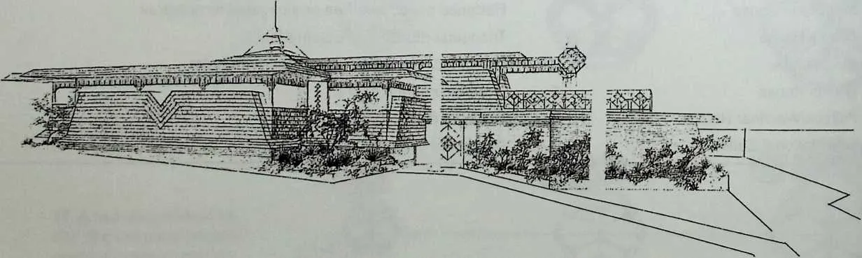
453 Figure2.3 Lawrence Hyde/Scott Lane House, Kansas City, Missouri, 1965. Rendered perspective.
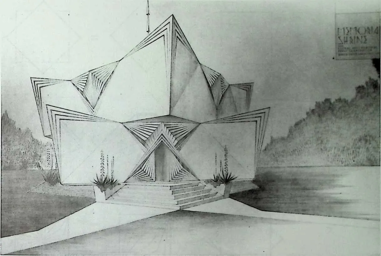
455 Figure 2.4 Floral Hills Temple of Rest, Project, Las Vegas, Nevada, 1960. Perspective rendering. (Courtesy of the Ryerson and Burnham Libraries of the Art Institute of Chicago.)
456 midal hood and large triangular mirror backdrop—approximating a virtual octahedron. De Long discusses the ‘‘earth, air, fire and water’’ symbolism in this convergence.28
457 The Floral Hills Temple of Rest, Project, Las Vegas, Nevada, 1960
458 This mortuary complex is another example of Stage 1 (Figure 2.4). Goff had taken the square and ‘‘made it his own,’’ as he might have said. Variations on the theme of one square overlapping another at 45° resulted in octagonal motifs varied by bends, folds, uplifts, thicknesses, contrasts, diagonal placement, and the like. Comers were stretched into tetrahedra and emphasized by bracketing lines at intervals of several degrees either more or less than 90° (Figure 2.5).
459 Mr. and Mrs. James Nicol House, Kansas City, Missouri, 1965
460 The Nicol House, as built (Figure 2.6), is the third and simplest of three designs.29 The first two schemes involved curvilinear forms—cylinders, cones,
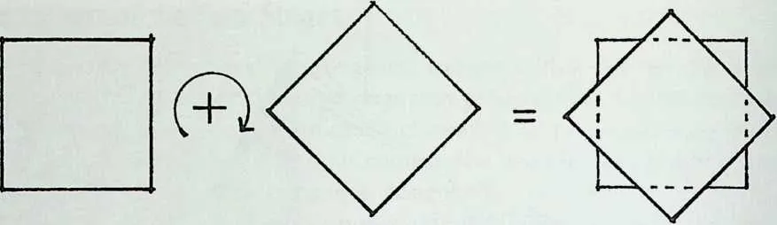
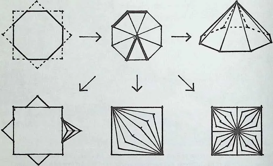
464465Figure 2.5 The Floral Hills Temple of Rest. Variations on the theme of one square overlapping another at 45°.
466beehive-like forms, warped planes, a helix, and so forth, probably beyond budget constraints.
467The third and finally built design for the Nicol House is a prototypical step ‘‘beyond the cube,’’ relying on vertical extrusion from forms other than the square and rectangle (Stage 2), principally variations on the octagon.
468Plan Octagons
469The floor plan’s most obvious pattern is based on an outer ring of eight octagons, each about 12 feet wide, with sides of approximately 5 feet, linked (or separated) by eight squares of the same edge length. Each of these outer octagons is thus centered on one of the eight vertices of a larger imaginary octagon (Fig. 2.1a). This outer ring of eight encircles four interior octagons, which in turn surround a fifth, central, focal octagon ‘‘conversation pit’’ (Figure 2.1b). These comprise the largest expression, although almost completely intangible, of a square-octagonal tessellation, creating the somewhat cruciform central living area or atrium (Fig. 2.1c). Other
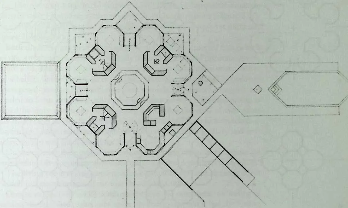
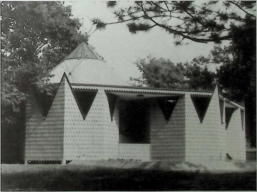
472 Figure 2.6 Mr. and Mrs. James Nicol House, Kansas City, Missouri, 1965. (a) Plan; (b) exterior photo. (Courtesy of the Ryerson and Burnham Libraries of the Art Institute of Chicago.)
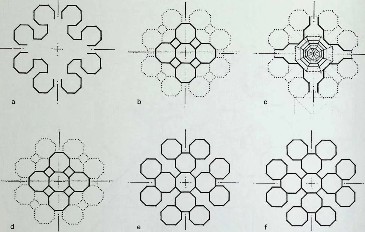
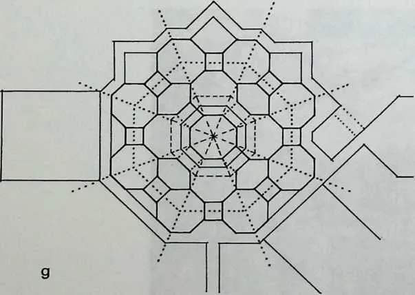
475 Figure2.7 Nicol House. Octagons: (a)ring of octagons; central square/octagon tessellation; (c) central living commons; (d) Examples of other square/octagon tessellation regions; (e) all 13 octagonal units; (f) all 12 square service/circulation units; (g)the complete grid; (h) a mandala of primary and secondary spaces; (i) perimeter, both floral-like and crystalline. clusters of two and three octagons occur as fragments of a square-octagonal tessellation (Figure 2.7d). The outer ring of 8 plus the atrium ring of 5 bring the octagon total to 13 (Figure 2.7e). These 13 functional domains alternate with 12 squares acting as service/circulation regions (Figure 2.7/). The entire grid system is at once simple and complex, unique yet universal (Figure 2.7g).
476 Both the outer group of eight octagons and the inner group of four (which abut one another) are extruded vertically to imply eight-sided prismatic spaces (Figure 2.8). They are implied—because walls occur at only five or six, rather than all eight, sides of each outer octagon, creating spaces defined by portions of octagonal prisms. Similarly, the four secondary (interior) octagons are extruded to form octagonal prisms. Each of these interior octagonal prisms is defined by only two walls—on opposite sides—plus the ends of two other walls that act as edges. Space ‘‘flows’’ in and out among these hierarchies—blossoming in a mandala with both central and peripheral, primary and secondary, family and private settings (Figure 2.7Zz).
477 On the exterior these prisms formed from the ring of eight outer octagons are clearly defined in a perimeter that is both floral-like and crystalline (Figure 2.1 i).
478 The living room ceiling consists of an eight-sided pyramid, the base edges of which intersect vertices of the four secondary octagons.
479 Obtuse angles (180°±45°) dominate the plan and contribute to a feeling of openness. Bruce Nicol, who grew up in the house, says that it had the feeling of ‘‘space without walls.’’
480 Windows on the four exterior walls of each octagonal prism, and in two cases on interior walls, consist of inverted 45° isosceles triangles. Their downward pointing 45° angle is the same as the angle subtended by the side of an
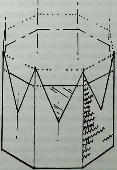
482 Figure 2.8 Nicol House. Octagons extruded into octagonal prism units.
483 octagon. Why the triangular windows? The use of conventional rectangular double-hung or casement windows would have ignored the octagonal schemata, squelched the visual dynamics, and destroyed the unity (Figure 2.8). Between each pair of triangular windows is a triangular region consisting of two walls meeting in a dihedral angle. This fold is both more and less than a ‘‘corner’’ because it is at a 135° angle and is emphasized by being at the central spine, or altitude, of a triangular motif. The ceiling and floor lines of these prismatic rooms participate in this angular dance.
484 The plurality of rhythmically spaced downward-pointing triangular windows complements the unity of the upward-pointing, octagonal-pyramid, central roof (and its similar pyramidal skylight). The herringbone shingle pattern is a textural reflection of this theme.
485 According to David De Long:
487488…The recessed, octagonal shaped area at the center focused upon an elaborate construction of Goff’s design: a wire sculpture linking the skylight above with a circular pool below. Again Goff had created a central feature in which a pool and skylight were linked, here enhanced by the addition of a third element—fire—and by the subtle motion and sound of the water as it moved down the wires, reinforcing unities. Its dramatic amplification of changing light added to its focal strength, transforming the room into an almost ceremonial space as strongly evocative of family position as any Roman domus. And like the atrium of a Roman house, or any number of similarly traditional models, the space was not conceived as a container of conventional furniture, but rather as a place of grander assembly, with more intimate, less formal areas provided elsewhere.30
489 In the original color scheme, on which Goff worked closely with Airs. Nicol, electric colors in the perimeter rooms contrasted strongly with the green central carpet. Bruce Nicol, who describes the colors as ‘‘very ‘60s,’’ has become a specialist in architectural interior color design.
490 The Nicol House is still essentially in the realm of the (vertical) extrusion, although ingeniously transcended on a relatively low budget. Variations on the octagonal theme affect doors, windows, tables, counters, and cabinets. However, their subtle visual and functional interrelations can only be understood and deeply felt through experience of the building.
491 Kathy Nicol reflects on living in the house:
492 …is a home a composition of pieces, design motifs, or a whole…
494495‘‘O chestnut tree, great rooted blossomer, Are you the leaf, the blossom or the bole? O body swayed to music, o brightening glance, How can we know the dancer from the dance?’’
496 —W.B. Yeats, ‘‘Among Schoolchildren’’
497 It is a question which needs to be raised about many of Goff’s constructions but few traditional buildings.
498 …invariably one of us would drag (Goff) off to see something in the house; the way in which a moon door framed a red bud limb or the reflection from the lily pool on a bedroom ceiling. BG always was pleased that someone had noticed and always claimed credit for having anticipated just such a phenomenon…BG stayed in the house for a month in 1969 when the entire family went away. It was the first, and I think only time he ever lived in one of his designs. He was singularly uncommunicative about the experience except to say that it was interesting…
499 The building itself inculcates a sense of possibility. It is not set squarely on the lot with a front door facing the street. Each room is visually open to nature on all sides and above. One need not look out a window or up through the skylight to know what the weather is. These serve more as frames than windows or skylights. The view from no two windows is the same. There is a sense of integration with the outside. The house changes dramatically during the day and during the year. In the winter when snow covers the skylights there is a sense of enclosure—not the sense of being protected from the elements but being enclosed by them. Snow never looks as soft and comforting on the ground as it does when one sees it from below on a skylight with the reflected light of a fireplace. In spring, the many trees which surround the house change from day to day. As they begin to blossom and then leaf, one is aware of the gradual change. Branches are close to windows and skylights so once again there is no need to look ‘‘out’’ a window; the ‘‘out’’ is brought into close proximity to the ‘‘in’’ and becomes a part of the interior decoration. The relationship is not only visual…one knows when the first rain falls and the sound of leaves falling and the wind blowing them about on the roof makes one realize why someone living in a cube might crave a recording of a waterfall or birds chirping. The two large moon doors also contribute to the noise factor; open—one hears not only birds, but squirrels, frogs and even the splashes as bats swoop at the pools drinking and eating bugs.
500 The sense when inhabiting the space is not of forms connected to other forms but of flow. There are no dead ends in the building…. Those corners which would shelter a corner chair are lined with built-in shelving at about three feet from the floor. The shelving keeps one back about 18 inches but more importantly, as the shelves are highly wood grained, a soft color, about fingertip level from a relaxed arm and continuous—the sense is to move about the space rather than to stop. The more prevalent corner—are they convex and concave?—is that which protrudes. These move the eye and even the body away from a dead end. They force movement along the line of one surface around the comer to the next which invariably leads into the central living area. The beds are on platforms which are continuous. If one sits in the living room and looks into the bedroom the color and texture continues from where one is sitting over the top of the conversation pit, across the floor and up the bed platform. There is flow rather than stasis. (…occasionally first time visitors say they get turned around in the house. I don’t understand but know that this would never happen in a cube.)
501 BG used Pella doors throughout the house so even the actual shapes seem to change with the closing and opening of these temporary divisions. The structure of the doors is a simplified microcosm of the building. The rolling feel of the shape and the sense of expansion or enclosing.
502 My parents have done no redecoration or modifications to the house, other than maintenance and removing my brother’s suspended bed, since the house was built. This is pretty weird when one considers that the house is almost thirty years old. However, the impetus to change and redecorate is subverted by the structure itself. The interplay with nature provides constant seasonal change. Additionally, as spaces are not confining but rather interrelated, visually expandable areas, one’s perception of the structure changes.
503 Having spent much of my formative years in the house, I must heartily agree with Winston Churchill’s belief: ‘‘We make our buildings then our buildings make us.’’
504 …The shingles on our house are grey stain and the interior carpet is green bordering on chartreuse. The ‘‘wire’’ fountain was long ago replaced by BG with a string and mirror sculpture. The lily pool is a square while the swimming pool is the elongated hexagon which is the shape of the shingles. Tvo tables are circular while two low tables are the negative space of the moon doors where the glass was inserted. These were impromptu designs which Goff devised when he saw the quality of the grain in the Japanese Ash which is used throughout the house. He felt the wood too beautiful not to use. This inspired the salvaging of most of the negative spaces…These forms and anti-forms provide a pleasant repetition and visual reversal throughout the house. …Both staircases are standard metal spiral staircases. The treads of these have been wrapped in carpeting but would more closely approach a triangular shape than an octagon. The stools which Goff designed are metal reinforcing bars with balls on one end and circular cushions on the other—the configuration repeats the crossed reinforcing bar design above each large skylight, over the chimneys and those on either post of the front gate.
505 Goff trimmed many areas with square mirrors in various sizes and textures. In the central skylight area there are downward pointing pyramids of these in the spaces where shingles come together. Along the front of the carport there are little rows of these mirrors set on edge. Although Goff used the octagon as a unifying shape, it does not in practice feel dominant. The drawer pulls are triangles and many cabinets and shelves are rectangles, cubes, or triangles. The doors have compressed squares and pyramids as metal trim. In living in the house and viewing the interior one is impressed by the interplay of many geometric forms rather than the dominance of one. The polyhedrality is to my mind far more complex than the repetition of octagons.
506 As to the personal side of living in an unusual structure, it has been a fascinating experience. It is hard for me to pull apart the influences and dissect what comes from being reared by people who hired BG, spending great quantities of time with him over a four or five year period when I was especially open to new ideas, and the influence of growing up in one of his creations. I always enjoyed living in the house growing up and often rated people by their reaction to it. I have been living here again recently and have a more developed respect for the design elements and the functionality. I am however still surprised by the fact that Kansas City or maybe the world in general has not yet caught up with Goff. It still rather startles me when people comment on the house. I have been dealing with realtors and potential buyers in the past few months and am flabbergasted that many people believe it demands some strength of character to not five in a box. When we first moved into the house I was about 14 and thought it very cool and wanted all my friends to comment. Gradually however, I began to feel that those who felt compelled to comment on the house were simply displaying a very narrow mind-set. Time has moderated my stance somewhat. It was a fabulous house for teenagers in the sixties; a great place for slumber parties; a great place to awaken one to the value of environment and the importance of living with beauty and many other very valuable lessons. . . .
507 P.S. I just finished this after nightfall and forgot to include how the house is never really dark. There is always some moonlight or even reflected city lights—it’s never like a windowless apartment bathroom. …Also during full moons when the moon is over my bedroom skylight I understand ‘‘lunacy.’’31
508 William H. Bass House, Project, Tulsa, Oklahoma, 1956
509 Before discussing polyhedra in the Bass House (Figure 2.9), we will let others summarize its formal and functional aspects:
510 According to Architectural Design:
512513The car port is screened from the road by a low wall of translucent glass along two sides of a lily pool. A covered walk leads through the car port across the forecourt of white raked sand, with reflecting pools, to the main entrance at the right. Tall louvered aluminium ‘‘light trees’’ illuminate this area at night. The entrance door is of pale green marble, as are all closet walls and sliding doors for same. From the entrance hall we may go into the kitchen, at the left, or into the ‘‘powder room,’’ coat closets and stairs up to the balcony. Sliding translucent glass doors in gunmetal frames open into the marble-floored recreation room with fountain. This space opens out on to the screened porch and sliding translucent glass walls open to the carpeted parents’ living-room and the daughter’s living-room.
514 Figure 2.9 William H. Bass House, Project, Tulsa, Oklahoma, 1956. (a) Plan; (b) rendered aerial perspective; (c) roof plan. (Courtesy of the Ryerson and Burnham Libraries of the Art Institute of Chicago.)
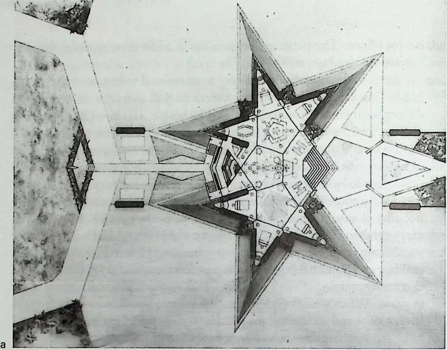
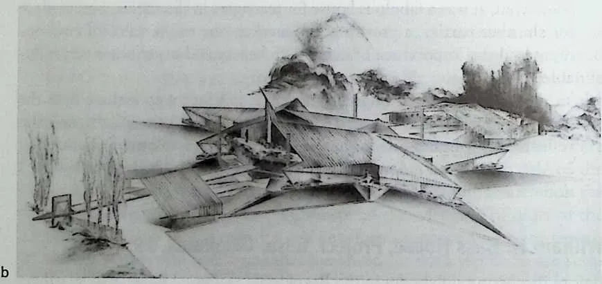
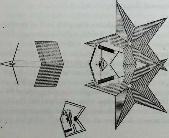
516 Bedrooms open off these living rooms, each with marble closet walls, dressing areas and baths. The dining-room opens off the parents’ livingroom and has direct service from the kitchen. A service entrance opens into this space, with servants’ stairs leading down to their rooms in the semibasement. A swimming pool adjoins the porch and dressing rooms and showers are connected by a wisteria-covered arbor.
517 The entire house is built on a star-shaped grass-covered berm, with gravel strip surrounding it for drainage. Sim bathing areas flank the swimming pool. The roof is of Stran-steel construction, covered inside with metal lath, sprayed with white acoustic-insulating asbestos …all furniture, including dinnerware, glasses, etc., will be designed by the architect. All baths are sunken marble-lined pools screened with translucent glass with planting beyond….32
518 And De Long:
520521…the Bass house project—resembles the Price Studio in appearance but is composed differently, for it extends the theme of the McCullough project…with modular shapes overlapped to form systematic variations of interior space. The repeating unit, however, is itself more complex: a five-pointed star. Four are overlapped to order both interior and related exterior spaces, and within the house a regular pattern of hierarchies results, with shared, private, and service areas given specific spatial character. These are programatically identical to the McCullough Scheme, and reinforce Goff’s tendency to express a Ghent’s desire for privacy through clearly defined geometries. Again he had produced a geometric metaphor for interlocking family structure [my emphasis—RR], one that stood in marked contrast to the more conventionally open and unstructured designs of the time, almost as if compensating for that which he had rarely experienced but perhaps sought to honor. Typical of Goff’s approach is his three-dimensional realization of the modular unit, here achieved by angled planes that reinforce the star image…. The house was to have been constructed of steel joists, with an exterior cladding of pale blue anodized aluminum. Inside, pale green marble was to be used for floor and wall surfaces and, in sheets suspended from wheeled ceiling tracks, as movable partitions. Goff explained that while the clients approved the design, they were discouraged from building by the strong protests of the neighboring residents.33
522 The floor plan of the Bass project was based on three abutting pentagons—suggesting dodecahedral development; however, the scheme developed instead toward a stellated pentagon (pentagram, or five-pointed star, two-dimensionally speaking). Two nonadjacent pentagon sides were extended until they intersected, creating an isosceles triangle, the base of which was the included side of the pentagon. In plan, the pentagon modules were each stellated on fewer than all five of their sides, resulting in partial pentagrams (Fig-
523 Figure 2.10 Bass House. Pentagon modules ‘‘stellated’’ into pentagrams.
524 ure 2.10). The plan is based on a stellated pentagonal grid—a small region of a quasicrystalline grid.
525 A startling expression of the pentagonal geometry was the double-star roof. Two intersecting pentagrams covered three pentagonal cores, their ridges bisecting the 36° pointed ends of the stars in a natural outgrowth of the plan. The roofs stars interpenetrated like mirror-image, twinned crystals. The owner was a two-star admiral! (Goff himself was in the Navy during World War II)—not the first Goff literal translation of a client attribute into a specific form—note Goff’s entry in the Cowboy Hall of Fame competition for Oklahoma City, 1956, in which the buildings were shaped like horseshoes!
526 Interiors consisted of free-flowing regions defined by pentagramal pyramid ceilings whose bases were low triangular walls resting on perimeter facias or light troughs, the soffits of which became the ceilings of the star arms. The pentagons were further defined by screens, glass, storage walls, seating areas, and so on at key vertices. As in the Nicol House, major spaces were virtual prisms generated by plan elements capped by corresponding pyramids, with subsidiary outcroppings around their edges.
527 The roof over a typical star arm had conventional two-slope pitch; however, the following handling of surface planes contributed to the polyhedral character (Figures 2.11 and 2.12):
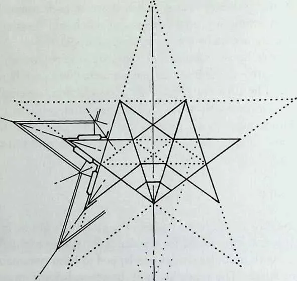
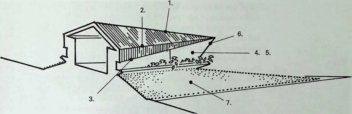
530 Figure 2.11 Bass House. Polyhedral star arm.
- 1.
- The ridge sloped upward from the outer tips of the star arms as the roof widened.
- 2.
- The roof consisted of four planes with three folds—the eave folds are horizontal.
- 3.
- The lower roof surfaces wrapped down vertically onto the walls, in effect becoming siding, their bottom edges sloped downward from the end points, circumventing the conventional wall/roof dichotomy. The roof predominated and walls became secondary. Examples of other Goff designs that employ this device are the Rudd icosahedral bedrooms, the Price Studio, and the Crystal Chapel.
- 4.
- Glazing the ends of the star arms removed the vertical wall planes and let the roof polyhedra dominate.
- 5.
- These glass walls tilted out at the top—creating a pentagonal cross section.
- 6.
- The apparent slope of the glass was doubled where the two sloping glass planes abut at the pointed ends of the star arms.
- 7.
- Landscape berming repeats the dihedral, pointed roof pattern, emphasizing the pentagram fingers. Angular planters articulate vertices where the star arms meet.
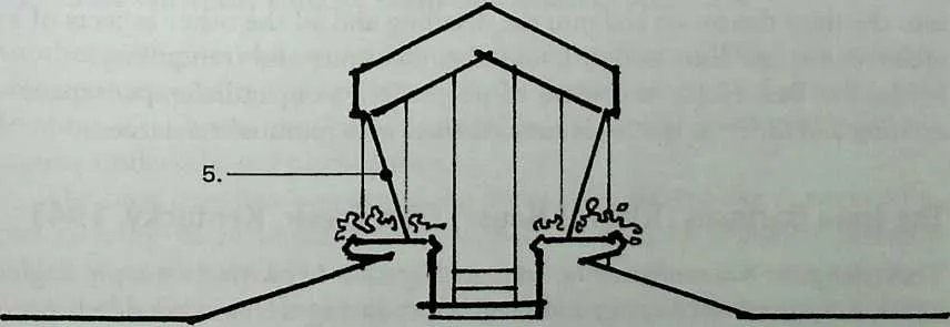
534535Figure 2.12 Bass House. Section through star arm.
536 All of this added up to quin-or pentapyramids (an extension of di-pyramid nomenclature); or, say, ‘‘partially-stellated-proto-icosahedra.’’
537 Intersections of two tip ends of the star arms are prominent in the front and rear of the house—the front intersection being articulated further into a mechanical shaft doubling as entrance totem.
538 A three-story front entrance area contains a multiplicity of functions—kitchen, powder room, closets, and utility rooms. Covering these elements are extensions of central portions of the roof—in a complex departure from the ‘‘purity’’ of the twinned pentagrams. Lateral halves of the star arms are extended straight beyond the ridge, rather than folding there.
539 The star theme proliferates in skylights, pentagonal diprism glass tables, stools and chairs, exterior planting, walkways, and sunken seating areas.
540 John Sergeant observes:
542543On a larger scale, the same problem [i.e., an ‘‘erosion’’ of the centralized geometry for an ‘‘act of entering’’ which is ‘‘somewhat mean’’] is exhibited in the Bass project…. A two-star admiral merits a grand plan with family pentangles; but ultimately there is the same clash between entrance and kitchen, which duel for the same geometric slot. The brilliantly developed geometrical hierarchy suffers from one of its points being a dining room while the others are bedrooms.
544It has been argued that this very abstract, ‘‘frozen’’ geometry is unworkable; it has been called ‘‘heraldic.’’ De Long, however, feels that it represents only an extreme development, and draws attention to the geometry as pattern. He suggests that the complication and ambiguity of architectural experience which result from such plans parallel the aims of Sufi architecture, where complex overlapping pattern was used to sustain contemplation. This may be so, but Goff’s handling of symmetry must also be set in Western culture.54
545 As this design is unbuilt, no one can vouch for the static-ness versus the fluidity of the interior space from direct experience. However, based on built designs with similarly strong generating patterns, for example, the Pollock/Warriner, Wilson, Nicol, and Price residences, the strength of the geometry and the rigor and variety with which the Bass pentagonal theme is carried into the third dimension and into the detailing and all the other aspects of its architecture, establish not only uniqueness, but unity and tranquillity.
546 In the Bass House the sense of polyhedral, nonparallelepiped space—exciting and different space—is strengthened with minimal resources.
547 The Irma Bartman (Triaero) House, Fern Creek, Kentucky, 1941
548 This triangular summer vacation cottage (Figure 2.13) with its steeply angled struts, dramatic overhanging, and shadow-producing trellises heralded several features that were later to appear in the Bass design: glass end walls, inclined wall storage units, and wraparound, ribbed siding. Together these elements
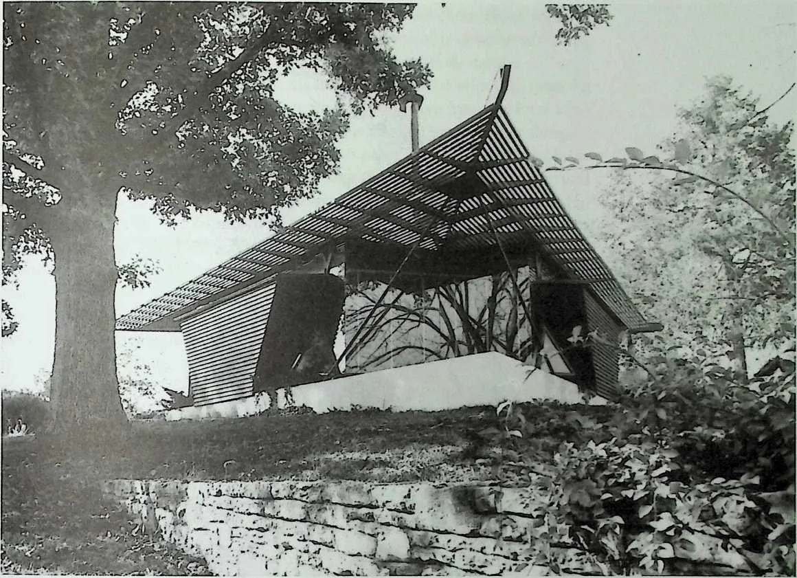
551552Figure 2.13 Irma Bartman House (Triaero), Fern Creek, Kentucky, 1941.
553dramatized the acutely angled corners of the plan, producing a feeling of more than just a prismatic, vertically extruded volume, in short, creating the emotional dynamics resulting from the use of polyhedra. The storage areas and glass end walls are a sort of hexagonal diprism, capped and enclosed by a triangular roof and stanchions that form a truncated octahedron.
554The Emil Gutman House, Gulfport, Mississippi, 1958
555Another triangular scheme, the Gutman House (Figure 2.14), built in hurricane country, was raised one story off the ground on pipe columns to avoid flooding. The house was ‘‘wind-proofed’’ by its ‘‘airfoil’’ profile of sloped triangular underside and pitched roof.
556The pipe columns supporting the house were arrayed like outspread fingers forming three tetrahedra-like clusters or inverted triangular pyramids (which were to have been enclosed in the first design, as were the towers of New York’s George Washington Bridge). In three tetrahedral pipe column clusters, a single one-inch-diameter steel rod tension member tied down the cantilevered floor trusses. Professor Robert Faust, of Auburn University, who
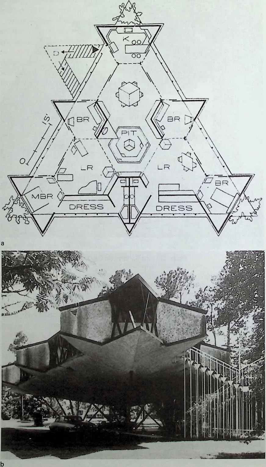
558 Figure 2.14 Emil Gutman House, Gulfport, Mississippi, 1958. faPlan; (b) exterior photo. (Courtesy of the Ryerson and Burnham Libraries of the Art Institute of Chicago.)
559 organized and supervised the construction was worried about those rods—if anything happened to one of them (e.g., a fire), presumably down would come the house. There was a fire, but it affected other parts of the house.
560 Faust said construction work on the house, which went smoothly, caused a great deal of excitement. Passers-by (many of whom were from the local Pensacola area) thought it was a bridge under construction, among other things.
561 The geometry of the scheme as a whole is based on a triangular grid hierarchy with a unit triangle of 7 feet on a side (Figure 2.15a). The structural supporting legs conform to this geometry—three inverted pyramids forming a tetrahedral/octahedral space-frame-like unit (Figure 2.15#). The interior spaces were generated by vertically extruding into prismatic volumes a plan tiling of triangles with one, two, or three comers truncated, creating both truncated rhombi and hexagons with unequal sides arranged within a larger overall triangle. The resultant plan is essentially a tessellation of equal-and unequal-sided hexagons with sides defined by partitions of varying degrees of
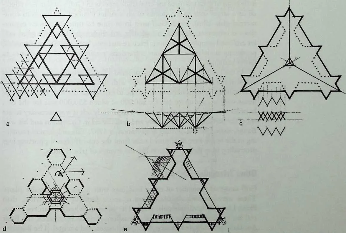
563 Figure 2.15 Gutman House, fa) Geometry, triangular grid hierarchy; (b) structure, inverted pyramids of supporting legs form a tetrahedral/octahedral space frame (with elevation). (c) roof plan, pyramid, soffit under similar (with elevation of diagonal structure), (d) open interior spaces—hexagonal tessellation, partition transparency and views, (e) peripheral service elements—closets, planting, porches, utilities.
564 transparency and movability, for example, drywalls, sliding glass doors, fixed glass, and folding wood doors as room dividers and closet doors (Figure 2.15d). In plan, again the polygon variations differentiated private, family, utility, and server spaces. In the Gutman House, however, most of the service elements—closets, planting areas, porches, utilities, stairs—are on the periphery (Figure 2.15e). The regularity, truncation, and size gradation of opposing triangular modules is clear in the Gutman House. Alternate triangular prisms are expressed on the exterior corners and midsides of the larger triangle. All are sandwiched between shallow triangular dipyramids (hence ‘‘airfoil’’). In other words, the roof (Figure 2.15c) is a shallow pyramid capped by a single-module tetrahedral skylight; the underside or soffit is a similar, but inverted, pyramid, the bottom of which accommodates a sunken seating area, the floor framing and mechanical equipment while portions of the upper pyramid are recessed to reveal sloped ceilings.
565 Faust said one thing that did not work as well as Goff expected for the Gutman House was the use of little chips of broken plate glass added to the stucco and to the driveway to make them sparkle. Albeit unsuccessful, these little chips of glass mirrored the crystalline aspects in Goff’s designs—reflected on a larger scale in the chunks of glass cullet (‘‘culled’’ waste from commercial glass kilns), which Goff used from time to time in various capacities—as ornament, masonry, and glazing. Athough crystalline, the glass cullet exhibited complex, curvilinear fracture surfaces, both concave and convex, producing undulant and sinuous refractions reminiscent of the shapes in Goff’s paintings.
566 In the 1980s the Gutman House suffered a fire of suspicious origin. It was said that the fire department, unfamiliar with the unusual design, was unable or unwilling to obtain access to the house to extinguish the fire. Faust said the house was then put up for sale for $80,000 of which $50,000 was for the site. In order to sell the property, the owners apparently felt it was necessary to get rid of the partially burned structure and demolished it. Grantham and his wife Bonnie visited the site on their honeymoon in 1987. The only traces remaining of the house were little rusted nubs from the cut-off pipe-supporting legs protruding from their foundation like the stumps of tree clusters.
567 Other Triangular Designs
568 Goff designed a number of other buildings with Stage 2 triangular plans. These were generally ‘‘tighter,’’ that is, more formally symmetrical, than Frank Lloyd Wright’s triangular plans. The salient polyhedral features of several are mentioned in the following discussion—private residences, the Briar Associates prefabricated projects, fraternity houses, and a motel. The Bartman (Triaero) House was discussed previously in conjunction with the Bass House. The Price Studio designs and the Crystal Chapel are covered further on. The Searing House was noted in passing. Each provides a unique example of a variation on the triangular theme—but they are by no means all simply prismatic spaces extruded vertically from triangular plans.35
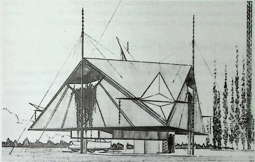
570 Figure 2.16 John Quincy Adams House, Project 1, Vinita, Oklahoma, 1958. Rendered perspective. (Courtesy of the Ryerson and Burnham Libraries of the Art Institute of Chicago.)
571 The John Quincy Adams House, Project 1, Vinita,
572 Oklahoma, 1958
573 The Adams House (Figure 2.16), like the Gutman House, was raised off the ground at three points but with a garage underneath—a modified octahedron—or dipyramid with the base enlarged (Figure 2.17). The house was partially suspended on cables from pylons at the centers of each side—the pyra-
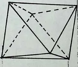
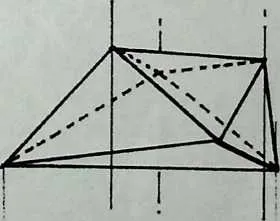
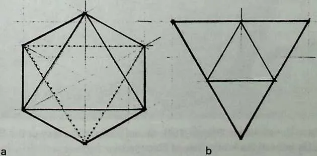
576 Figure2.17 Adams House.
577 (a) Octahedron, two views; f/V Adams House, side view and plan.
578 midal cable arrangements complementing and giving rise to its polyhedral character, since the polyhedral edges of the house followed the cable lines. Triangular windows with Y mullions created ‘‘virtual’’ tetrahedra.
579 The Helen Unseth/Sheldon Newman House Designs
580 Version 1—Project, 1939
581 The tetrahedral-like clusters of roof trusses of the first Unseth design (an equilateral triangle in plan) were not rigorous space frame or tetrahedral-octahedral matrices, but rather, three-dimensional prismatic grids
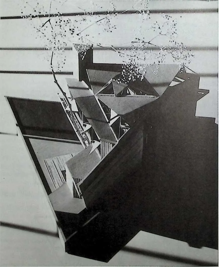
583 Figure 2.18 Helen Unseth House, Project, 1939. Model photo. (Courtesy of the Ryerson and Burnham Libraries of the Art Institute of Chicago.)
584 resulting from interlocking two-dimensional trusses—an early suggestion of the Sierpinski arrowhead mentioned below in connection with the Crystal Chapel (Figure 2.18).
585 Version 2 of the Unseth House, as Built in 1940, in Park Ridge, Illinois
586 The plan is a square cut in half along the diagonal, forming an isosceles triangle. The focal point of this small and modest-seeming house is a dynamic composition of fireplace opening, sunken hearth, flue, windows, and skylight, together carrying into the third dimension the diagonally cut-square theme. A similar functional/polyhedral cluster surrounding a fireplace was seen in the Hyde House, discussed previously.
587 Triangular windows are covered with shutters that are ‘‘die cut,’’ as it were, from the continuous diagonally lapped board siding. When opened, a shutter, together with its window opening, create a virtual tetrahedron. A similar polyhedron is implied in a corner of the bathroom by two back-to-back triangular windows.
588 The present owner of the house, Sheldon Newman, feels that the house is a bit small for his present needs—but that the character of the house more than compensates. Mr. Newman said he felt that to know a Goff house one should know about the client, because Goff carefully tailored his designs to their needs. From neighbors he found out that Ms. Unseth was an artist and horticulture lover who had planted most of the site—now fully mature over half a century later. From the interiors the windows bear a striking relationship to the trees and bushes outside—the 45° angled sloping sills provide surprisingly harmonious frames for the spreading crowns of the yard foliage. (The same is true of the Nicol House windows.) A tiny triangular window at the floor level may have provided a view of a favorite plant outside.
589 Briar Associates Projects, Bartlesville, Oklahoma,
590 1963 and 1964
591 Goff again used triangular and hexagonal prisms (vertically extruded—Stage 2) in the several designs for the Briar Associates prefabricated structures. House A was based on the hexagon whereas House B and Cabin A were based more on truncated triangular prisms. Cabin A, with its clearly expressed riveted metal shell, was supported and raised above grade, like the Gutman House, on three steel finger-like ‘‘quadripod’’ arrays—inverted pyramids. Triangular windows at the corner truncations of Cabin A (similar to those of the Nicol House) were shaded by the sharply pointed cantilevered prows of the roof, which extended the equilateral triangle of the plan out to its vertices.
592 Black Bear Motor Lodge, Project, Jackson Hole, Wyoming, 1961
593 The tepee-like tetrahedral ‘‘dormer’’ windows that enliven the roofs of the Black Bear Lodge (Figure 2.19) connote a Native American theme—a theme that is inevitably suggested whenever a conical (or many-sided polygon-based
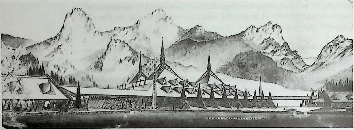
595 Figure 2.19 Black Bear Motor Lodge, Project, Jackson Hole, Wyoming, 1961. Rendered perspective. (Courtesy of the Ryerson and Burnham Libraries of the Art Institute of Chicago.)
596 pyramid) form is used, as in Goff’s Crested Butte Lodge and a number of other projects. The Black Bear motel rooms are grouped into three rectangular blocks, which in turn are arranged as a triangle. Within this triangle are three dining, communal, and service tetrahedral spaces—all one story above grade. This frees up the ground level for parking, circulation, landscaping, and a swimming pool at the center, which is open above. Tapered skylights cap the ridges of the tetrahedral roof of each major space and, together with a similar tapered spire from the peak, create a four-pronged (tetrapodal), stellated-like crown (Figure 2.20)—three of which dominate the motel silhouette. Zigzag masonry walls enclose the whole and frame sharply pointed balsam fir and spruce trees, which echo the rooftop spires—all set against and perhaps inspired by the jagged mountainous backdrop.
597 Figure 2.20 Black Bear Motor Lodge. Tetrapodal crown/skylight.
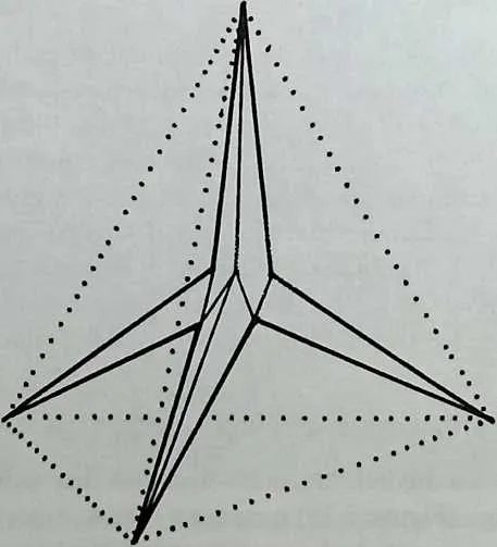
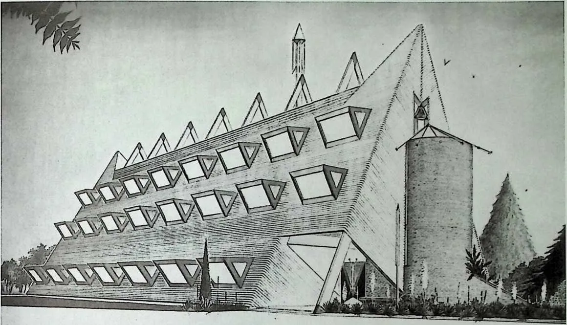
600 Figure 2.21 Phi Sigma Epsilon Fraternity House, Project, Talequah, Oklahoma, 1962. (Courtesy of the Ryerson and Burnham Libraries of the Art Institute of Chicago.)
602603Phi Sigma Epsilon Fraternity House, Project, Talequah, Oklahoma, 1962
604A series of ‘‘A-frame’’ structural members created a triangular prism upon the sloping wall/roofs of which nestled rows of complementary triangular prism ‘‘dormer’’ windows (Figure 2.21). A similar volume, but a negative variation on the prism, provided an inviting and protective entrance. Related clusters of rooms occur in the fraternity houses and the motels as they are both multiunit residences.
605 W.R. MacBryde House, Project, Kansas City, Kansas, 1959
607608The MacBryde House (Figure 2.22), like the Gutman and Adams houses, is raised one story with the garage remaining at grade. Diagonal corner porches are joined visually by railing walls with sloping tops that create an illusion of the entire house resting on a flattened half-cuboctahedral base. Like the Gutman House, interior volumes are expressed on the exterior as triangular prisms with sloping bases, penetrating the partial cubocatahedron that defines the perimeter. As in the Pollock/Warriner House, here the structural framing runs at a 45°angle to the overall massing of the house.
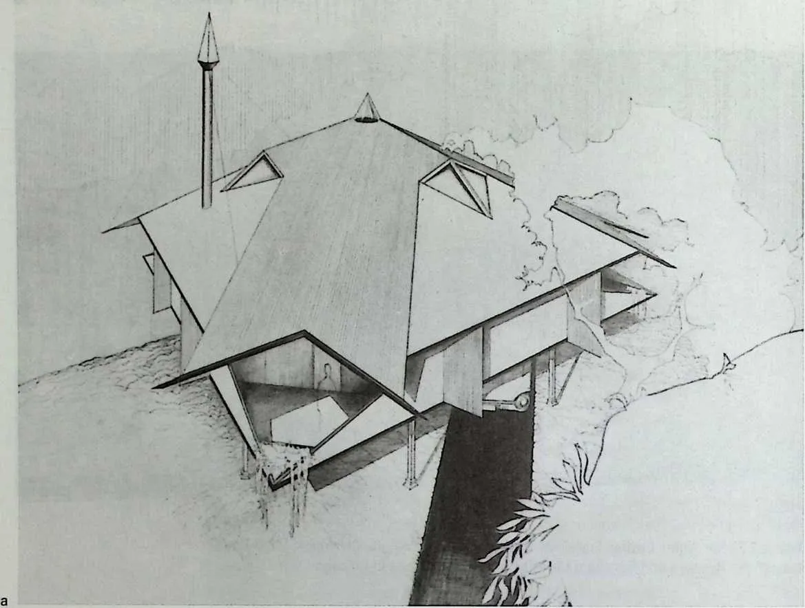
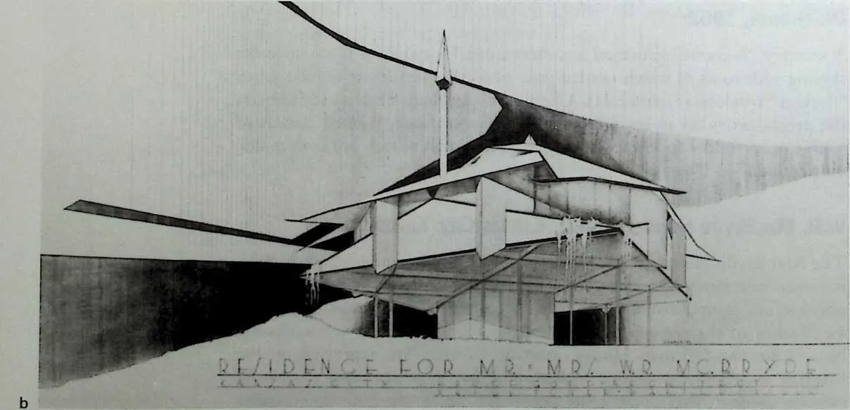
612613Figure 2.22 MacBryde House, Project, Kansas City, Kansas, 1959. (a) Bird's-eye perspective; fworm's-eye perspective. (Courtesy of the Ryerson and Burnham Libraries of the Art Institute of Chicago.)
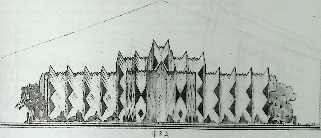
615 Figure 2.23 Phi Beta Delta Fraternity House, Project, Norman, Oklahoma, 1930. Rendered elevation. (Courtesy of the Ryerson and Burnham Libraries of the Art Institute of Chicago.)
616 Phi Beta Delta Fraternity House, Project, Norman,
617 Oklahoma, 1930
618 The Phi Beta Delta Fraternity House (Figure 2.23) was an elaborate Stage 1 project, basically a T-shaped plan, with its member cells canted—producing a ‘‘sawtooth’’ plan, which gave each room a corner window, expressed the multiplicity of rooms, and created a dynamic, spatial exterior. Goff had designed a high school in 1930 along similar, serrated lines. The corridor between two banks of rooms, as a result of this canting, contained wedge-shaped volumes, which would have invited ‘‘schmoozing.’’ A typical cell comer window consisted of back-to-back triangles—again, the virtual tetrahedron (Figure 2.24). These ‘‘tet’’ volumes dominated the exterior of the building and the balance of the exterior wall surfaces were diagonally and triangularly patterned and scaled so as to unify them into an abstract composition (what today we might lazily call art deco), emphasizing the vertical stacking of rooms and downplaying the horizontal. Frank Lloyd Wright used the wraparound window early on (e.g., the Henderson House, 1901), as did Le Corbusier (e.g., the Amedee Ozenfant Studio, 1922).
619 Pi Lambda Phi Fraternity House, Norman, Oklahoma, 1955
620 As in the Black Bear Lodge, the mostly rectangular spaces in the Pi Lambda Phi Fraternity House—a dining room, private rooms, and offices—were contained in three longer rectangles, which in turn defined the edges of a large, two-story, interior triangular commons (Figure 2.25). At the three comers where these rectangles met, the resulting triangular entrance and related spaces were extruded vertically into prisms. A very flattened half-cuboctahe-
622 Figure 2.24 Phi Beta Delta Fraternity House. Corner windows compared: (a) Frank Lloyd Wright's Henderson House, 1901; (b) Le Corbusier's Ozenfant Studio; (c) Goff's Phi Beta Delta Fraternity House, virtual tetrahedron.
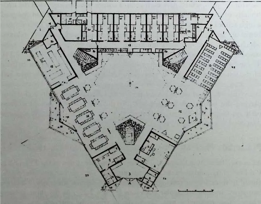
624 Figure 2.25 Pi Lambda Phi Fraternity House, Norman, Oklahoma, 1955. Plans. (Courtesy of the Ryerson and Burnham Libraries of the Art Institute of Chicago.)
625 dron roof with triangular clearstory windows covered the communal area, topped by a large, open-frame, steel pipe tetrahedron, from the apex of which hung sculptural television antennas. A prototype for the central triangular prism defined by three peripheral rectangular spaces is apparent in Goff’s 1924 design for a recital hall in Tulsa, and is echoed two-dimensionally in the floor plan of the Crystal Chapel.
626 First NatioiniaD Bank, Project, Independence, Missouri, 1970
627 James Nicol (of the Nicol House discussed previously) was an officer of the First National Bank of Independence (Figure 2.26) and was instrumental in getting Goff the commission for a new building for the bank—the second of two projects (the first had been a remodel).
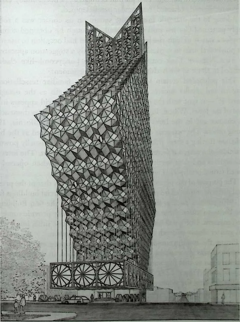
629 Figure 2.26 First National Bank, Independence, Missouri, 1970. Rendered perspective. (Courtesy of the Ryerson and Burnham Libraries of the Art Institute of Chicago.)
630 The core of the bank was a load-bearing structural steel frame enclosing stairs, elevators, and utilities. The structural members of the core were exposed at the top of the building and cutaway into a crown that formed half of a virtual cuboctahedron. From this core were cantilevered floors of graduated lengths—one could argue that this might lend variety to rental potential—creating the most striking polyhedral element of the building—a tower mass as a square rotated 45° to stand on its corner. The visual device of increase in width toward the top was used occasionally by Wright, for example, the Rogers Lacey Hotel project in Dallas, 1946,56 and, of course, the Guggenheim Museum in New York. Goff’s design, however, increases in width much more rapidly from the base upward to its midpoint and then decreases equally. A square with this orientation seems less a square—more a quadrangular polygon—its corners predominant. The edges we are used to in conventional architectural boxes are either parallel to the ground or vertical, the comers scarcely noticed. This portion is Stage 2—a horizontally extruded, nonrectilinearly oriented, rectangular parallelepiped.
631 Adding to the dramatic mass of the square on its corner was a robust, deeply patterned Cor-ten steel curtain wall. Although he obtained commissions for a variety of high-rise buildings, Goff never had occasion to use modular polyhedral units in vertical close packing—only a suggestion appeared in the First National Bank curtain wall. Was the honeycomb-like cladding intended to allude to the beehive of the office environment?
632 This polyhedral curtain wall was based on a familiar tessellation of octagons and smaller squares with the same edge length as the octagons, turned 45°—in sync with the office tower massing. This grid appears in the plans of the Jones, Wilson, Pollock/Warriner, and Nicol houses discussed in this chapter and in the Innis House, Project, Coronado, California, 1943, among others. The octagons of the First National project acted as the bases of shallow (having a short altitude relative to the width) but visually powerful pyramids—the octagons were large—equal to the story height. The intermediate squares and their vertically pivoting window sashes when opened 90° formed virtual octahedra (Figure 2.27).
633 The purpose of this pyramidal dimpling was the same as that of the pressed metal patterns employed frequently for cladding of commercial buildings from the 1950s onward, such as the aluminum curtain wall of the 666 Building in New York—to stiffen a thin metal sheet and simultaneously provide some tex-ture/omament. Goff’s wall had a real depth but, at the same time, imparted an even greater illusion of depth through its pyramid symbolism.
634 Fitting the multipyramidal integument to the sloping ends of the 45° office block was accomplished by a slide transformation in which the pyramids were cut so that five segments stayed in place and three slid inward to the next story (Figure 2.28). ‘‘Slide’’ surfaces resulted in an accordion pleat, strongly defining the sloping end walls. This curtain wall is a proto-Stage 4 polyhedral tessellation.
635 Cor-ten steel was the rage for a while in the 1950s and 1960s—it was a preoxidized (rusted) steel alloy that would presumably oxidize only up to a
636 Figure 2.27 First National Bank, Independence, Missouri. Virtual octahedron window.
637 Figure 2.28 First National
638 Bank. ‘‘Slide’’ surfaces result in accordion pleat.
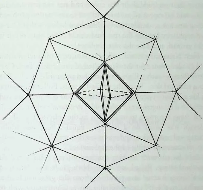
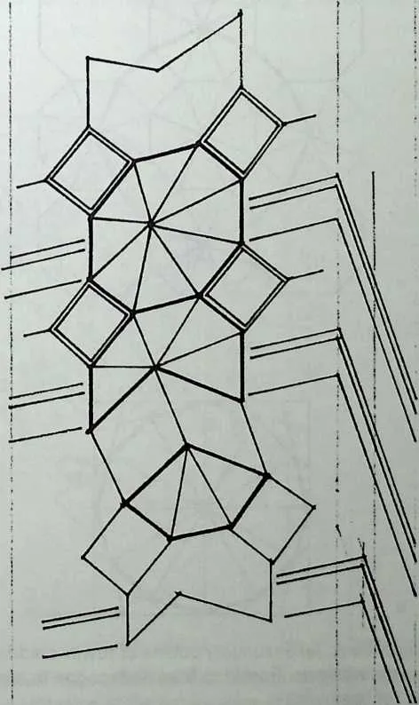
640 point, retain die rusty reddish-brown color, and not require painting. Structural steel could be expressed as steel without maintenance problems (where fireproofing was not a consideration). Grantham believes that Cor-ten eventually lost popularity because the rust dust would bleed onto other buildings, drip to the ground, and stain the surroundings.
641 The First National’s curtain wall is reminiscent of Buckminster Fuller’s 1958 steel geodesic dome for the repair shed of the Union Tank Car Company in Baton Rouge—each utilizes prefabricated pyramidal steel cells to form a continuous stiffened skin. There the similarity ends. Fuller’s was another variation on his geodesic system, involving tension and compression rods as part of the hexagonal arrangement of sphenoidal structural cells, each cell varying in size and shape according to its location in the spherical geodesic pattern. Goff’s design was based on a uniform, equal-celled, essentially planar, square-octagonal tessellation, and was not structural, beyond its self-bracing, nor was it, of course, covering a spherical surface.
642 The floor for customer banking transactions was a box—redefined with Goff’s personal stamp. Raised one story above grade and distinct from the office zone above, it acted as a transition from the ground plane and as an underlying base to the 45° angled volume above. Contrasting with the opaci -
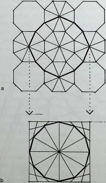
644 Figure 2.29 First National Bank, (a) Secondary outline of tower cladding is reflected in (b) banking floor rondelle windows. Transition from dodecagon to square frame is done with ‘‘curve stitching’’ of beams.
645 ty of the textured steel mass above it, the banking floor was transparent—enclosed by giant glass ‘‘rondelles’’ on one long side, on the end walls, in the ceiling as skylights, and set in the floor as well. A variation on the tower cladding, it comprised 12-sided, tempered-glass pyramids whose base perimeters consisted of overlapping steel beam frames, another example of curve stitching (Figure 2.29). This ‘‘cage of steel and crystal’’ hovered over the plaza, suspended on cables from the floors above. As Goff said to Grantham (who spent a month drawing the intricate perspective), ‘‘Same old unusual stuff.’’
646 When First National was bought by a larger bank, the project was dropped.
647 The Howard Jooues House, Bartlesville, Oklahoma, 1958
648 The Jones House (Figure 2.30) has an open plan that does not readily admit to polyhedral discoveries. The floor plan is based on squares and octagons in tessellation—the same pattern as the grid of the First National Bank curtain wall discussed previously. Had the Jones House plan tessellation been carried into the third dimension (e.g., had the squares and octagons been orthographically projected in front and side elevation as well as plan) to create an aggregation of polyhedral cells, it might look something like the schematic representation of a sodalite crystal.’’
649 Major functions such as living and dining inhabit the various octagons,
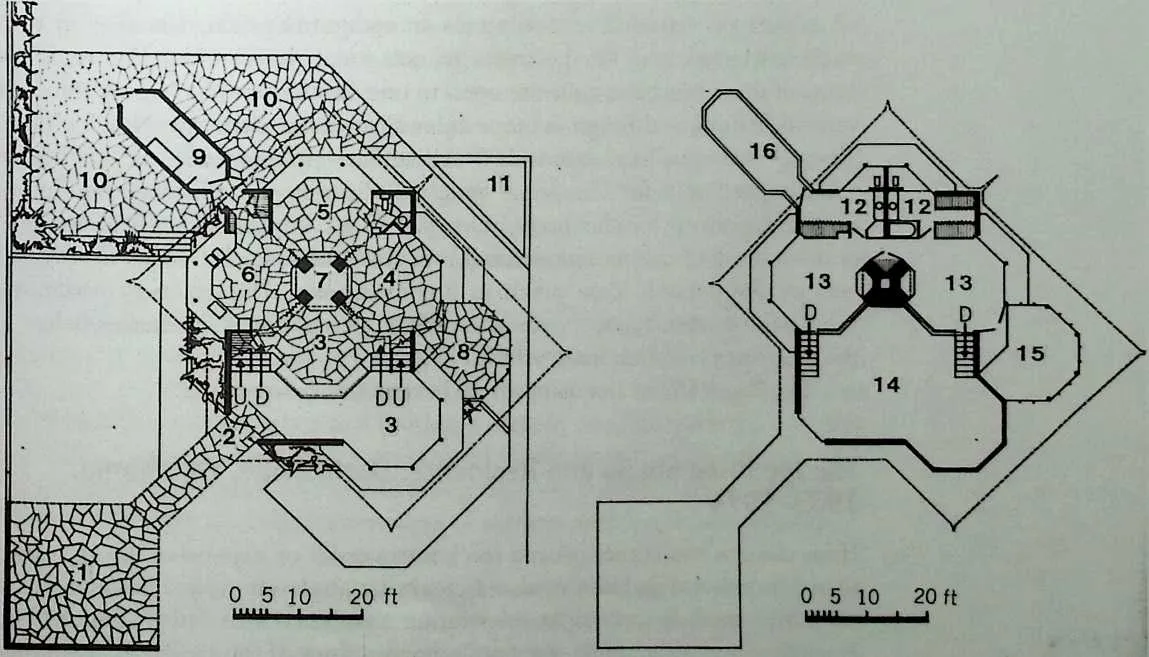
651 Figure 2.30 Howard Jones House, Bartlesville, Oklahoma, 1958. Plans. (Courtesy of the Ryerson and Burnham Libraries of the Art Institute of Chicago.)
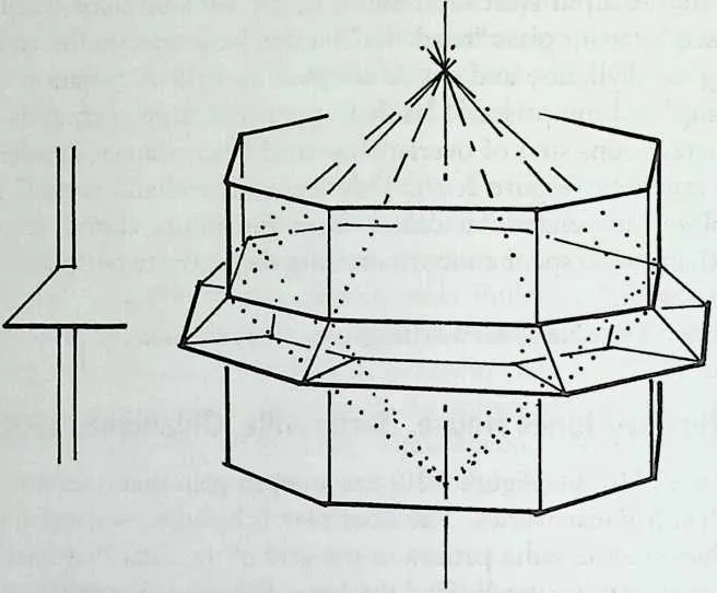
653 Figure 2.31 Howard Jones House. Octagonal prism penetrated by octagonal dipyramids—schematic view and section.
654 which He at different levels, whereas the square elements comprise circulation and service modules—stairs, fireplace, and so on. A basic unit of space consists of an octagon extruded vertically into an octagonal prism, which is in turn encircled by portions of the frusta of octagonal dipyramids (Figure 2.31). Most of these prismatic units are open to one another and have only minimal vertical definition through exterior sidewalls—fewer than the Nicol House. The frusta—girdling bands of triangular prisms—act as showcase window/shelf units for Airs. Jones’ pottery collection—an important architectural determinant for this house. One senses a complex and spacious openness—a sense of the monumental. Three 1892 Oak Park houses by Wright contain the pyramid cum prism in a conventional 19th-century juxtaposition—with steep octagonal pyramid roofs on octagonal prism spaces below—the Thomas Gale, Emmond, and R.P. Parker Houses.
655 The Jones House Hes somewhere between Stages 1 and 2.
656 The Joe Price Studio and Residence, Bartlesville, Oklahoma, 1953–1974
657 If his designs sometimes proved too controversial or expensive, Goff, rather than compromise and dilute, would create a completely new scheme, using a simplified module or straight lines rather than curves or fewer angles. The Price Studio is an example—stepping down a rung of the ladder to a simpler polyhedral stage—from Stage 3 to Stage 2.
658 Morphologically, the Price Studio designs were (in brief): Scheme 1—lin-
660661ear clusters of rhombic frusta along the x, y, and z axes. This scheme was rejected for reasons discussed later. Scheme 2a was a ‘‘pinwheel’’ theme with vertical walls and a pitched roof. Scheme 2b had a similar plan but with sloping walls, creating less conventionally prismatic spaces. This scheme was built in 1956 and will be referred to in the following discussion simply as Scheme 2. It received two additions—a gallery and a meditation room.
662 Scheme 1
664665Scheme 1 (Figure 2.32), unbuilt, consisted of variations on rhombic frusta arranged in additive series or stacks along the x, y, and z axes. The approximately 90° opposition of each axis to the other two created a three-pronged reference armature in space, strongly expressive of three-dimensionality. The application of this spatial tool—individually articulated x, y, and z axiality (Figure 2.3 3zz)—occurs not only in the multiplanar work of Frank Lloyd Wright (e.g., the Robie House) but also in that of Le Corbusier and Mies van der Rohe (the Barcelona Pavilion is an easily read example). In the Price Studio 1 nonrectilinear volumes, that is, frusta and prisms, rather than planes or boxes, are oriented along the x,y, and z axes (Figure 2.3 3£). The slight inclination of these axes to one another parallels a common property of crystals.
666XAxis. The thematic unit volume of the Price Studio 1 was the rhombic frustum (Figure 2.34zz), extending horizontally and approximately perpendicular to the slope of the hillside site (Figure 2.34#). The cushioned, carpeted lower inclined surfaces of these frusta were seating/lounge surfaces.
667Variations on this theme abound—large and small, frustum, pyramid, and prism, vertical, horizontal, and sloping, abutting and branching, and so on. The main studio space was a linear series consisting of two frusta of rhombic pyramids of different ‘‘altitudes’’ (I emphasize ‘‘altitude’’ because in this case it is horizontal, whereas we usually think of the altitude of a pyramid as being vertical) with their truncation faces abutting, plus two rhombic pyramids, in a generally ABB\AX relationship, with pyramid and frustum bases back to back (Figure 2.35a)—or two pyramids interpenetrating vertex to vertex with a rhombic pyramid terminating each end.
668At each end of the x-axis array, dormers frusta sprouted like crystal growths or plant buds, a literal expression of organic architecture—part window, part skylight (inspired by the unfolding spout of a milk carton?)—glazed by boring holes in the glass and bolting it direcdy onto the gasketed opening.
669Side planes of the B frusta overlapped to shield and define bands of skylights, fighting fixtures, and ventilation grilles—at the same time emphasizing the frustum edge and the separateness of surfaces and downplaying solidity.
670Y Axis. Penetrating the x’-axis volumes at not quite a right angle in plan (in keeping with the rhombic theme, i.e., angles other than right angles) was a prism extruded parallel to the slope of the hill. The hill slope appears to have been a major determinant of the rhombic theme—the hill’s angle of repose projected onto each of the x, y, and z dimensions—schematically, if
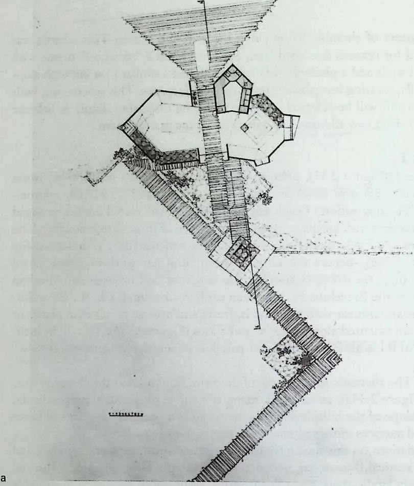
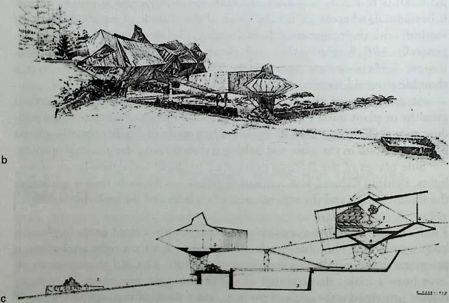
673 Figure 2.32 Joe Price Studio and Residence, Project (Scheme 1), Bartlesville, Oklahoma, 1953. (a) Rendered plan; (b) rendered exterior perspective; (c) section. (Courtesy of the Ryerson and Burnham Libraries of the Art Institute of Chicago.)
674 Figure 2.33 Joe Price Studio, Scheme 1 (project), (a) Generalized x, y, and z axiality; (b)x, y, and zaxiality in the Price Studio.
675 Figure 2.34 Price Studio, Scheme 1. (a) Rhombic frusta; (b) hillside slope as generator of the angles of the rhombus.
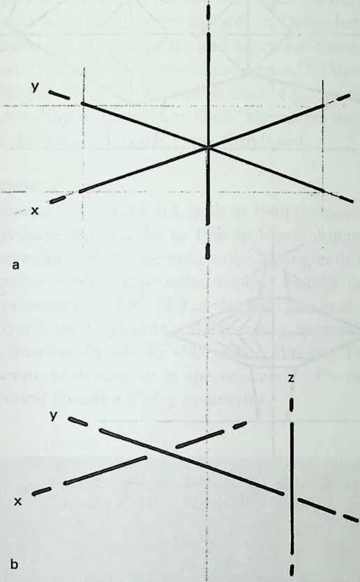
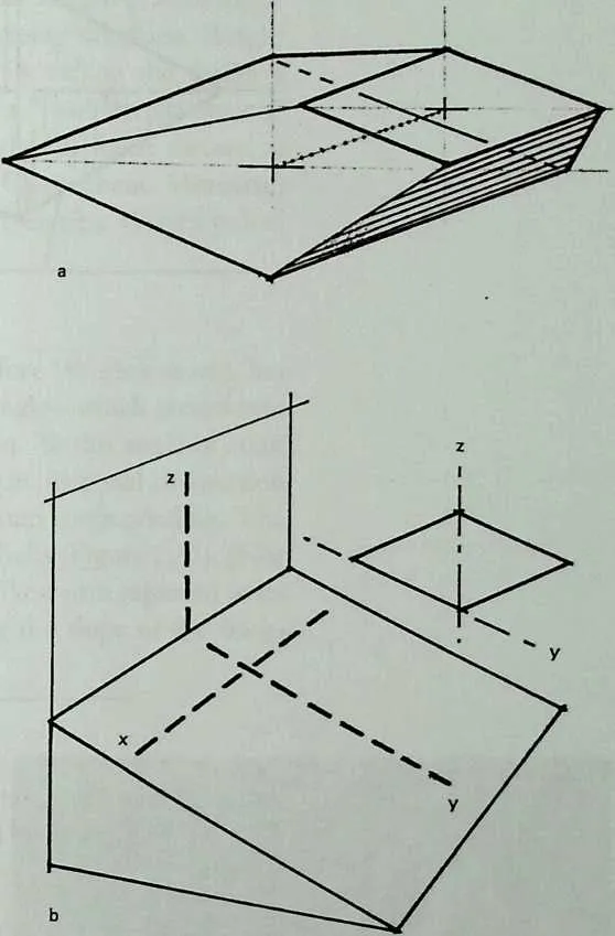
677 not strictly. The base of this inclined prism was a square tilted at 45°. (The First National Bank was a variation on this theme.) A wood ramp within served as circulation—carport, entrance, and bridge. The prism acted as tunnel and watercourse for a stream passing through the house, terminating in a waterfall on the downhill side. In addition to square and triangular elements, the pentagon (if somewhat modified) can also be found in the Price Studio 1.
678 ZAxis. Several variations on the prism array were related to the (vertical) z axis. One was an outdoor lounge or screened porch (Figure 2.35Z>). This was an ABBiAi stack on a vertical axis, the bottom A acting as a stone base holding up the central BBi porch—a dipyramid. A horizontal deck was placed within the canted sides of the inverted pyramid. It was topped by another A1 frustum—
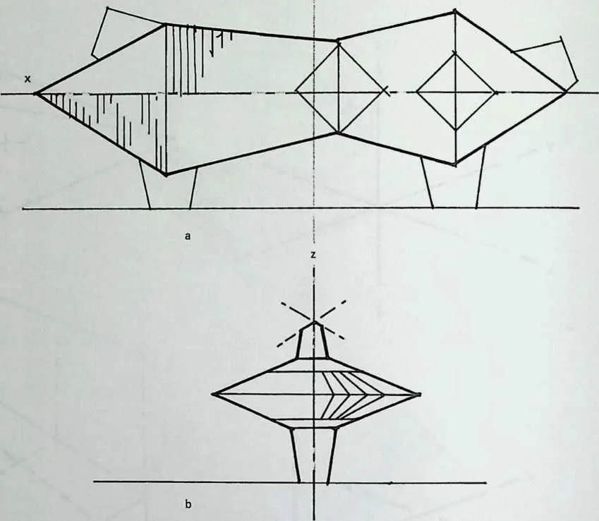
680 Figure 2.35 Price Studio, Scheme 1. (a) Main living area with horizontal ABBA arrangement of units; (b) screened porch, with a vertical variation of the ABBA sequence.
681 lighting fixture. The z-axis array consisted of, in other words, back-to-back bent pyramids. Another variation on the z-axis grouping was a kitchen/bath-room/darkroom service module near the entrance.
682 The rhombic polyhedra of Scheme 1 hint at the illusory effect of that well-known psychology experiment in which an object at the end of an experimental room with diminishing dimensions seems larger than normal because of the unexpected distortion in perspective. In other words, a frustum might exaggerate its own perspective, a property we will encounter again in the Crystal Chapel.
683 Early in the 1920s Goff heeded Wright’s admonition to his followers not to copy his forms but rather to find their own way. Goff was motivated to steer clear—apparent in his propensity to create crystalline forms as spaces that could be occupied. According to Larry Grantham, who feels that Goff’s work can be interpreted as ‘‘building-as-ornament,’’ such spaces came about as the logical development of two-dimensional ornament being made three-dimensional. Goff contrasted this concept of ‘‘building-as-ornament’’ (a concept that he explored in his ‘‘273’’ design lab at the University of Oklahoma) with that of applied local ornament. In teaching, Goff characteristically neither advocated nor rejected these ideas, but simply put them forward as possibilities of which to be aware.
684 The Price Studio was sited directly across a shallow valley facing the Harold Price House designed by Frank Lloyd Wright. Wright reacted negatively to the design for the first Price Studio. After seeing the plans, Wright wrote a scathing letter to Goff in December of 1954, calling the design a ‘‘travesty,’’ an ‘‘elaborate and expensive fiasco,’’ and a ‘‘manifest aberration’’ that ‘‘violated the concordant repose.’’38 (Similar barbs had been thrown at Wright’s work from time to time, e.g., against the Guggenheim Museum!) According to Grantham, Goff ‘‘altered his course forever after Wright pulled in the reins.’’ Scheme 1 was abandoned.
685 Scheme 2
686 Scheme 2 (Figure 2.36), built in 1956 (three years before Wright’s death), has a cross section similar to Taliesin West’s sloping rectangle—which carries into three dimensions the nonrectilinear angles of the plan. To this angle of cross section, Goff compounded another angular motif—the diagonal orientation (approximately 20°-70°) of the gold anodized aluminum roofing/siding. The effect is both dynamic and illusionary, approaching a helix (Figure 2.37). (Nor is, incidentally, the 45°-90° grid of Wright’s Taliesin West plan repeated in its elevation/section—it is approximately 15°—recalling the slope of the background Paradise Valley mountains.)
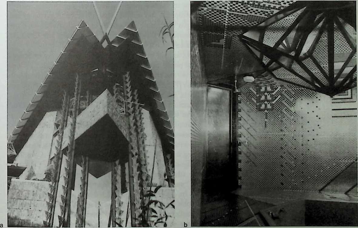
689690Figure 2.36 Joe Price Studio and Residence (Scheme 2), Addition, Bartlesville, Oklahoma, 1956–1974. (a) Loft; (b) photo of tile bathroom with pool above. (Courtesy of the Ryerson and Burnham Libraries of the Art Institute of Chicago.)

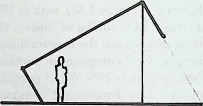
692 Figure 2.37 Price Studio, Scheme 2 (built). Schematic roof plan, elevation, and section.
693 The Price Studio is the most opulently appointed of Goff’s residences with its deep pile carpets, its famous goose-feathered ceiling, and its built-in Goff designed murals, sculpture, and stained glass; however, in terms of spatial concept, other designs were more daring, for example, the studio’s first scheme, the Bavinger House, the Dewlin Aparture project, and the first Garvey House design (the latter three are curvilinear).
694 Still, the Price Studio, as built with its additions, is a symphony of Stage 2 triangular and hexagonal prisms and dipyramids, of truncations, elongations, shifting axes, twinning, bi-and triaxial and rotational (pinwheel) symmetries of plan and roof structure (Figure 2.38), finials, stretching, bending, rhythms, branching, ornamentation, and texture.
695 For example, an aquarium at the center of the Japanese Painting Gallery (the first addition to the studio—a hexagonal prism motif) consists of an inverted hexagonal pyramid, the faces of which are subdivided into shallow triangular (triakis) stellations (or pyramids). The water reflects and refracts, multiplying the edges, vertices, and planes, adding to the pool’s crystalline, polyhedral quality, giving it the feeling of a large cut diamond.39 A similarly framed skyfight was designed for the roof directly above.
696 A meditation room (the second addition to the studio), described by some as ‘‘kaleidoscopic,’’ reprises the rhombic frustum theme of Scheme 1, like Petroushka’s ghost. Its roof is a rhombus folded into an elongated tetrahedron (in crystallographic terms a tetragonal bisphenoid) and truncated at the ends to produce smaller, similar virtual tetrahedra (Figure 2.39). The windows of Scheme 2 are another variation of the folded rhombus/virtual tetrahedron.
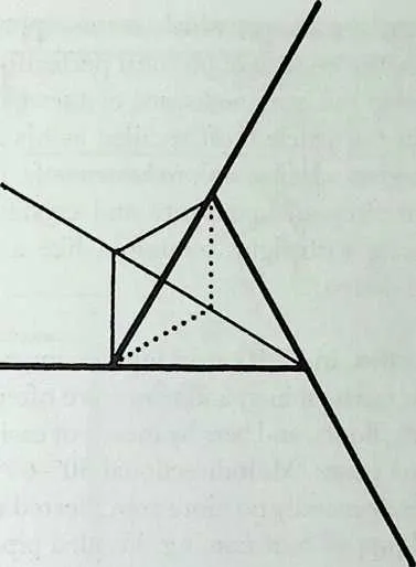
698 Figure 2.38 Price Studio, Scheme 2. Schematic ‘‘pinwheel’’ roof framing and pyramidal skylight over living room.
699 De Long discusses further symbolic and metaphoric aspects of the crystalline nature of Goff’s design:
701702Images of crystals …permeate his work, from such large-scale expressions as the Crystal Chapel…to such small-scale applications as the windows of the Snyder project…. In no example does such imagery seem more clearly intended than in the Price studio, beginning with the unbuilt project of 1953, where shapes shown in the exterior perspective closely resemble a quartz crystal Goff had in his collection…. In the built design of 1956 the crystalline forms of the aluminum-clad structure, reinforced by the prismatical details of the windows, sustain the image…. The studio appears to emerge from foundations of coal and encrusted glass as if it were a crystal in formation, recalling Expressionist postulations regarding the transformation of coal into precious gems, a form symbolic of the highest ideals. Manipulations of glass, mirrors, and coal within the Price
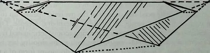
704 Figure 2.39 Price Studio, Scheme 2, second addition. Schematic roof configuration—virtual truncated tetragonal bisphenoids.
706707studio augment the image, which seems appropriately symbolic, for it would embody the essence of physical perfection and provide for an ideal retreat set within the imagined space of a jewel itself. This seems close to a statement in the article Goff recalled as his introduction to such concepts: ‘‘Thick glass, clear or colored, for roofs or walls or floors, opens up unconjectured vistas of luminosity and crystalline splendour, causing a house to vibrate with light, to unfold like a jewel of many forces, of dynamics and design.’’40
708 A Note on Construction. In Goff’s working drawings 30°-60° elements such as window mullions, facias, siding, and trim were often anchored to 90° components such as studs, floors, and bars by means of easily shaped transition pieces such as bent metal plates. Multidirectional 30°-60° cuts and fillets in woodwork for walls were generally no more complicated than those encountered in, say, conventional hipped roof framing. Welded pipes and rods were easier to bend and join in a nonrectilinear way. Beveling was accomplished as it is in ordinary construction. In short, the construction process was not inherently different—there were just more non-90° angles. Scheme 2 was based on a triangular grid (as were, incidentally, many Wright houses).
709 Joe Price said, ‘‘I didn’t want to go out and build an angular house.’’ That had been Goff’s way of fulfilling his client’s needs. ‘‘One result of living in it is that I knew it. When you have glass cullet in the wall you’re conscious of it and you never go up against it—if it’s in your mind. Oh, I’ve had a couple of guests who were drunk and got some scrapes—nothing serious. But nobody sober—because you’re always conscious of it.’’ The Prices have since moved west and now five in a house designed by another former Goff assistant, architect Bart Prince. Price quips, ‘‘There isn’t an angle in it. We knew we could run into it head on and not get a bruise!’’
710 The the former Price residence was tragically destroyed by fire in December 1996 (arson is suspected).
711 The Crystal Chapel, Project, Norman, Oklahoma, 1950
712 The Crystal Chapel project (Figure 2.40), developed for a University of Oklahoma site in 1950, was to have been, as its name implies, a chapel that was literally and figuratively quite crystalline—a jewel-like pyramid, faceted with roseate glass (hailproof—important for Oklahoma!) mounted on a 3O°-6O° angled stainless-steel grid structure—double glazed and translucently insulated. Each glazing unit consisted of a rhombic pyramid, intensifying the organic ‘‘self-similarity.’’ The petal-like corners of the pyramid opened up to act as inviting entrances and to nestle an extended tetrahedral steeple. Opaque, tetrahedral, subservient spaces (choir and meeting rooms) terminated two corners of the main glass pyramid—contrasting with its luminosity but harmonizing with its shape. The 300-seat chapel was the dominant form of a pair of buildings. The other contained a multiuse student religious center with classrooms, meeting rooms, and ancillary spaces, within a rectangular plan. Its
713 Figure 2.40 The Crystal Chapel, Project, Norman, Oklahoma, 1950. (a) Plan; (b) model photo of chapel; (c) interior rendered perspective. (Courtesy of the Ryerson and Burnham Libraries of the Art Institute of Chicago.)
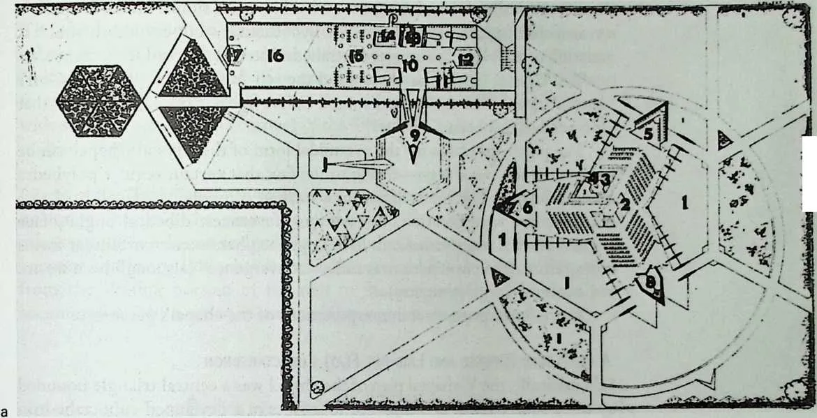
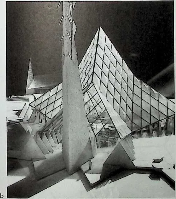
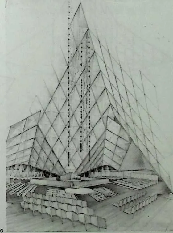
715 sloping side walls of rhombic glass were held in a grid similar to the chapel’s—a tessellation with roots in Goff’s 1922 hypothetical study for a cathedral.41 A variation of the chapel’s elongated tetrahedral steeple marked its entrance.42
716 The Crystal Chapel nearly realized the self-fulfilling prophecy of Goff’s youthful dream ‘‘to design a diamond palace for a maharaja.’’ Recall that Goff’s father had been a jeweler.43
717 The polyhedral basis for the pyramidal form of the Crystal Chapel can be interpreted in several ways—owing to the fact that certain regular polyhedra are interrelated. The interrelationships include component counts, axial orientation, face configuration, distribution of vertices, dihedral angles, face angles, and dual transformations. In biology the phenomenon of similar forms arising from different functions is called ‘‘convergence’’ (although here we are just concerned with geometry).
718 The following are several interpretations of the chapel’s geometry:
719 A Developed (Opened and Laid out Flat) Cuboctahedron
720 Schematically, the Y-shaped plan of the chapel was a central triangle bounded by three square arms, or wings—or four faces of a developed cuboctahedron (Figure 2.41).
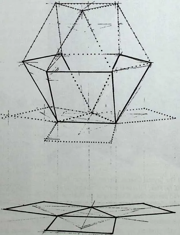
722 Figure 2.41 Crystal Chapel. Schematic plan elements of the chapel folded into a portion of a cuboctahedron.
723 A Tetrahedron
724 The third dimension in the chapel’s development was derived not from the cuboctahedron but rather from the central plan triangle—and from the tetrahedron (triangular pyramid). The triangular comers at the base of the tetra faces were folded outward like tent flaps—three pairs in all, not unlike the wide starched wings of the coronet of the Sisters of Charity or Japanese origami birds (Figure 2.42).
725 Effects of the ‘‘Tent Flaps.’’ On so opening, the bottom edges of the flaps were no longer hugging the ground, a problem similar to that encountered in relating geodesic domes and other polyhedral volumes to the ground plane—encountered in the Pollock/Warriner, Wilson, and Rudd Houses. Transition from the sloping bottom of the wall to the horizontal ground plane was accommodated by a series of graduated pink granite supporting piers, each of
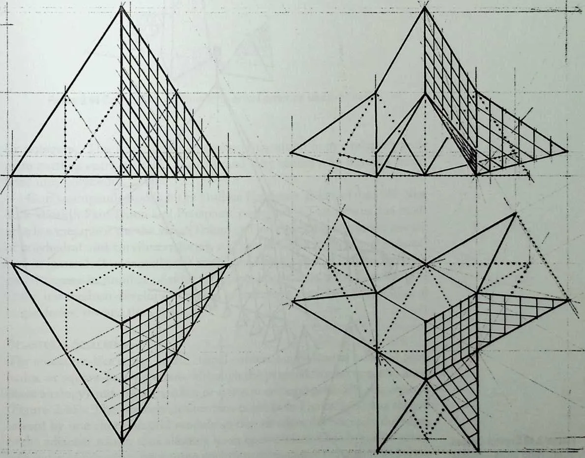
728729Figure 2.42 Crystal Chapel. Origami-like folding of a tetrahedron. Coronet.
730 which was an equilateral triangle in elevation and a rhombus in plan—a rhombic pyramid—or half of an oblate octahedron (Figure 2.43). These shrinking triangles acted as cross sections of attenuated, virtual, horizontal pyramids—matching in scale and flanking, but at right angles to, the main steeple (Figure 2.44). Their repetition suggested procession and their receding size would have created the perspective illusion of a longer passage and diminishing scale as one approached the central major space of the chapel, making the latter seem more monumental. Nave bays and other elevation features (balconies? planters?) in Goff’s hypothetical study for a cathedral in 1922 foreshadow the gradation of dimension and the repetition of the isosceles triangle.44 This ‘‘forced’’ perspective recalls Bernini’s shrinking Scala Regia (or expanding, depending on which way one is headed). The enabling ‘‘depth cue’’45 is the ‘‘slope,’’ that is, a gradual change in size of a series of similar objects, or the angular relationship of lines in a triangular motif. Two adjacent legs of a triangle have a more pronounced convergence toward their common vertex than do, say, two adjacent sides of a square or of other regu-
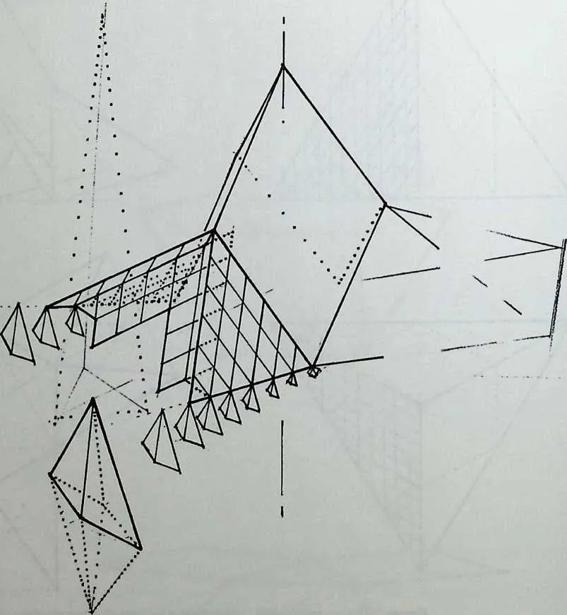
732 Figure 2.43 Crystal Chapel. Supporting piers—halves of an oblate octahedron.
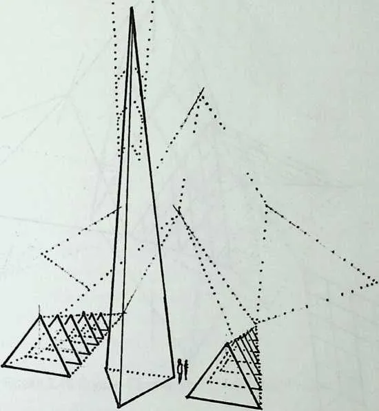
734 Figure 2.44 Crystal Chapel. Piers form virtual pyramids similar to steeple.
735 lar polygons. The traditional ecclesiastical transition from a relatively intimate narthex entrance space into a grand lofty central nave was thus translated into polyhedral geometry.
736 Goff’s campanile nods a bit to Wallace Harrison’s Trilon, of the 1939 New York World’s Fair Trilon and Perisphere centerpiece. That famous duo mod-erne is a metaphor for the yang (Trilon) and yin (Perisphere) opposite pairing of polyhedral and curvilinear forms, not just in Goff’s work, but in architecture in general. (Incidentally, the twain could meet hypothetically as the polygon increases in number of sides to approach a circle or three-dimensionally as the tetrahedron develops by stages of increasing face plane subdivision, as in geodesics, toward the sphere.)
737 Octahedral Stellation
738 The stellation-like wings at the chapel comers can be read as halves of octa-hedra, or square-base pyramids, although the pyramid face between the inner (nave analogy) and outer (narthex or transept analogy) polyhedra was omitted (Figure 2.45). The opposite, outer face plane (a in Figure 2.45) was slipped inward by one rhombic grid module so that its edges did not meet the edges of the adjacent wings, thus alluding to an open projected window. This created a sense of hovering, beckoning enclosure surrounding the steeple and choir and gave the glass a sense of folded, enveloping surface—of weightlessness.
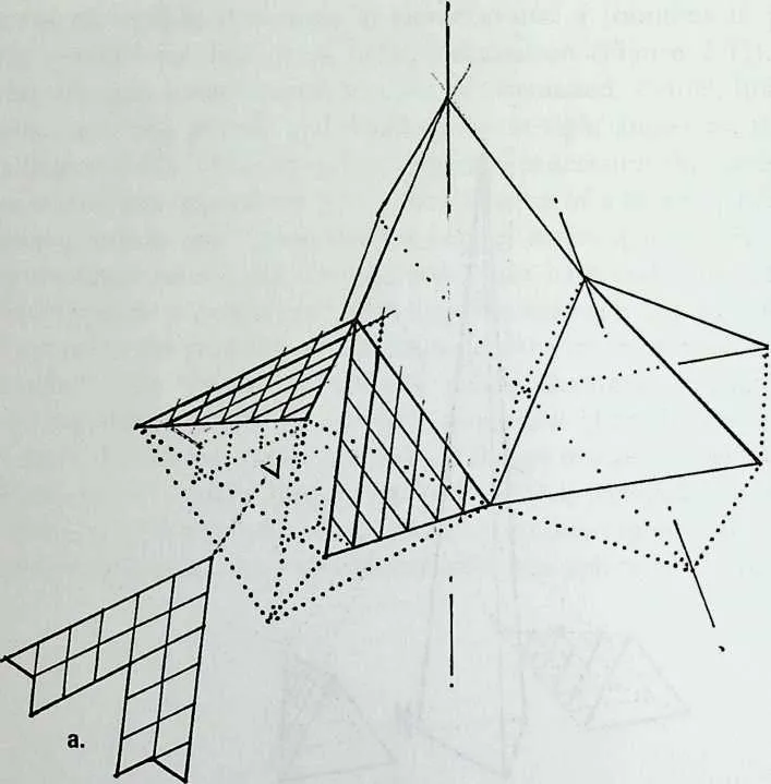
740 Figure 2.45 Crystal Chapel. Octahedral ‘‘stellation.’’ Face plane ‘‘slippage.’’
741 The feeling of solidity and mass that is imparted by closed, opaque faces with abutting, congruent edges was thus substantially decreased. A similar overlapping and offsetting of planes occurred in the Price Studio 1.
742 Rhombic Hexahedron
743 These comer ‘‘flaps’’ surround, isolate, and emphasize three major central 60°-120° rhombi of the chapel roof, defining half of a rhombic hexahedron (Figure 2.46). A rhombic hexahedron (or oblate rhombohedron) is like a cube (hex = six, i.e., six faces) that has been distended by pulling two diagonally opposite comers so that the cube’s faces become diamonds (rhombi). In the PoUock/Warriner House we encounter one-half of a related polyhedron—the rhombic dodecahedron (12 faces). The half, rather than the whole, in each case is due to the truncating intersection of a polyhedron with the ground plane.
744 In the Crystal Chapel did the conception of the tetrahedron come first, origamicized, as it were, with its flaps—an example of a modified Platonic solid projected orthographically onto the ground plane, or was it one of the other polyhedra mentioned previously? Or does it matter? Because in the finished design square, triangle, hexagon, rhombus, tetrahedron, octahedron, rhombic hexahedron,and so on are orchestrated into a complex composition of variations.
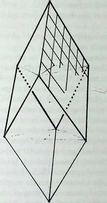
746 Figure 2.46 Crystal Chapel. Haifa rhombic hexahedron.
747 The Crystal Chapel: A Historical Perspective
748 The Crystal Chapel’s position in modern architectural history is a fascinating adjunct to its geometry. It is linked by evolution and influence from the early 19th century through the present. It is a mid-2 Oth-century focal point for noteworthy unified major spaces enclosed by metal and glass. Suffice it to mention here a few precedents and antecedents—designs involving transparent or translucent pyramidal forms with more or less triangulated or rhombi-cally faceted surfaces. These related buildings anchor the Crystal Chapel in time like prongs securing a jewel in a setting—upholding Goff’s design as an important statement of spatial unity, impact, and grandeur. As composer James Heath put it in the title of a composition dedicated to fellow musician John Burkes Gillespie, ‘‘Without You, No Me.’’
749 By the mid-19th century, metal-and-glass construction had come into its own—heralded by the budding greenhouses or ‘‘palm furnaces’’ erected in Europe, and later long-span structures such as train sheds—climaxing in the mammoth 1,851-foot-long prefabricated Crystal Palace Exhibition Hall in London, 1851, designed and built by Sir Joseph Paxton. Perhaps Goff, who taught the history of 19th-and 20th-century architecture, intended the Crystal Chapel as a centenary homage to Paxton’s structure.
750 A throng of experiments arose in the early 20th century—Bruno and Max Taut’s expressionist
Glass Pavilion for the Cologne Exhibition of 1914 (actually a pointed dome, rather than a
pyramid) and their competition entry for
a House of Friendship in Istanbul, 1917, as well as the various crystalline mountain-like forms of
the designs in their publication, ‘‘Alpine Architecture,’’ 1919.46
751 Wassili and Hans Luckhardt’s House of Culture and other projects (circa 1919–1923) were equally utopian.47
752 Two Goff religious projects of 1930 use steeply pointed triangular motifs interacting with shallow triangular bases: the Gaudf-influenced Hypothetical Study for a Cathedral and the Hillcrest Methodist-Episcopal Church, Tulsa.48
753 Frank Lloyd Wright’s work offers a wide range of crystalline examples:
754 His Steel (and glass) Cathedral project, 1926, with its staggeringly immense atrium—a truly Boullean scale commensurate with Wright’s talent and vision—predates any John Portman hotel atrium.
755 At the opposite end of the scale, an early expression of the pyramidal idea in Wright’s domestic work can be seen in his Owen Young House, Chandler, Arizona, 1927—a ‘‘textile block’’ project with 45° angled fenestration and massing.
756 The Unitarian Meeting House, Madison, Wisconsin, 1947, with its magnificent prow—is more of a pyramid-like ecclesiastical extension of a Usonian house. Surprisingly, the interior of its main meeting area is ceilinged not by pyramidal but by warped planes—something of a rarity in Wright’s work—in this case a natural result of the ceiling, truss, and roof configurations.
757 Wright’s Trinity Chapel project, 1958, designed some 10 years later for the same site as Goff’s Crystal Chapel on the University of Oklahoma campus, was also unbuilt (Figure 2.47). Wright’s design (the barest hint of a precursor to a Sierpinski arrowhead49) appears to be a variation on Goff’s Crystal Chapel. Although not so much a ‘‘crystalline’’ building, it is still a variation on pyramidal forms—with a gradual transition from the completely flat and horizon-
758 Figure 2.47 Trinity Chapel project by Frank Lloyd Wright. Transition from horizontal to vertical.
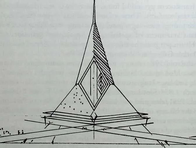

760 tai ground plane upward through four basic functional/massing elements to a vertical spire at the peak: long shallow criss-crossing ramps, a trio of opaque buttress-like tetrahedral walls, three large stained-glass rhomboid windows nestled among these tetrahedra, topped by three long, narrow, folded, leaf-like roof forms,50 which come together in their upper halves to terminate in a tapered spire. There are even echoes of the top of the Chrysler Building here! The roofs are V-textured, probably standing-lock-seam metal and reminiscent of the roofs of Wright’s Nekoma Country Club project.
761 Thus Goff’s chapel is echoed by Wright’s in at least four themes: the rhombus, the tetrahedron, the ‘‘bent’’ theme (i.e., graduated slopes), and the triangular symmetry of plan. Both chapels assign distinct materials for different functions; however, Wright uses the more traditional architectural elements of individuated base, wall, window, and roof.
762 Wright’s Beth Sholom Synagogue, Elkins Park, Pennsylvania, 1953–1959, bears comparison to the Crystal Chapel. Although its two intertwining tripod structural frames (symbolizing the intersecting triangles of a Star of David) hark back to Wright’s steel cathedral, the roof is translucent and three comers of its modified hexagonal plan are terminated by opaque tetrahedral-like masses, and the changing slopes are again evident.
763 The Wayfarer’s Chapel, Portuguese Bend, California, 1946, by Frank’s son, Lloyd Wright, is not pyramidal (although it is dramatically sited, like a Greek temple, on a hillside overlooking the Pacific Ocean), but it is more or less rhombically faceted and wholly transparent.
764 Skidmore, Owings, and Merrill’s U.S. Air Force Academy Chapel, 1957, is neither transparent nor pyramidal, but its rhombically faceted (‘‘folded-plate’’) structure, rectangular plan, and serrated roofline recall the classroom wing of Goff’s Crystal Chapel complex.
765 The Religious Center, Project, Artesia College, New Mexico, 1976, by Goff, once again in an academic setting and also called ‘‘Crystal Chapel,’’ is a series of multisloped or ‘‘bent’’ pyramids with extensive transparency—a variation on his chapel in Norman, with ‘‘intensified angularity, less symmetrical massing of the pyramidal shapes, and less regular glazing,’’ according to De Long.
766 The Artesia chapel was a transparent pyramid. Its decreasing mullion spacing and the resultant wedge shapes of the glazing acted together to create gradients—depth cues—which increased the apparent slopes and heights (Figure 2.48). Transverse mullions spiraled gradually upward. Motion was symbolized—appropriately ascendant. Dynamism, however, was only implied here, in contrast to the literal kineticism of Goff’s Rudd House (discussed later), which had movable walls. Of course, large moving sections of buildings, such as entire roofs (covering stadiums) or rooms, are not uncommon, as in some works by, to name a few, Calatrava, Lautner, and Site.
767 The Artesia multisloped pyramids had a family resemblance to the frustum clusters of the first Price Studio project—notably the latter’s freestanding screened pavilion—as well as Goff’s Ski Lodge, Crested Butte, Montana, 1965 (Figure 2.49), based on a 16-sided pyramid (with this many sides it is
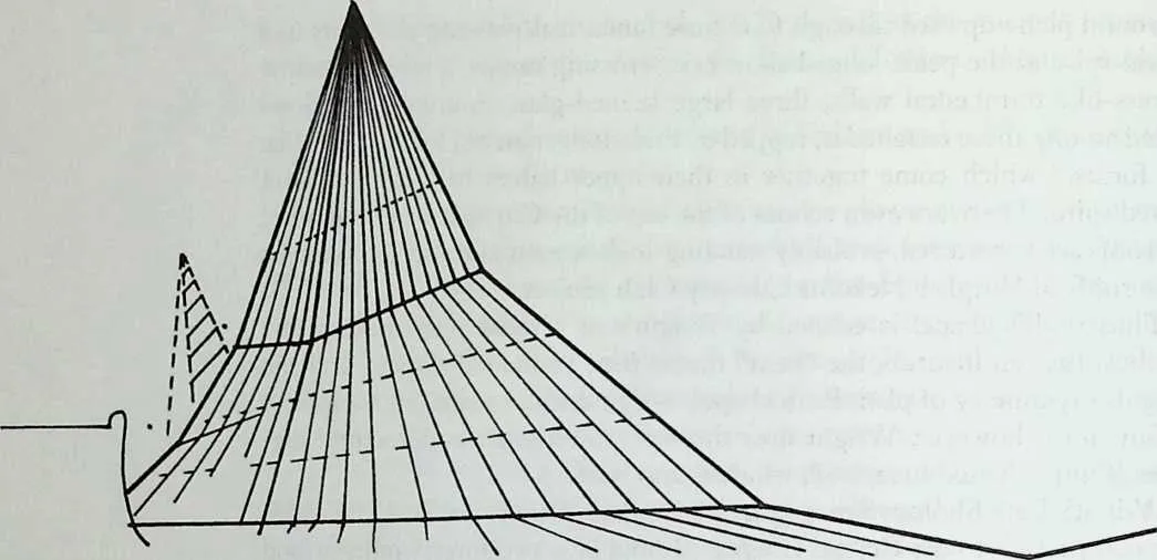
770771Figure 2.48 Artesia Religious Center. Multisloped pyramids.
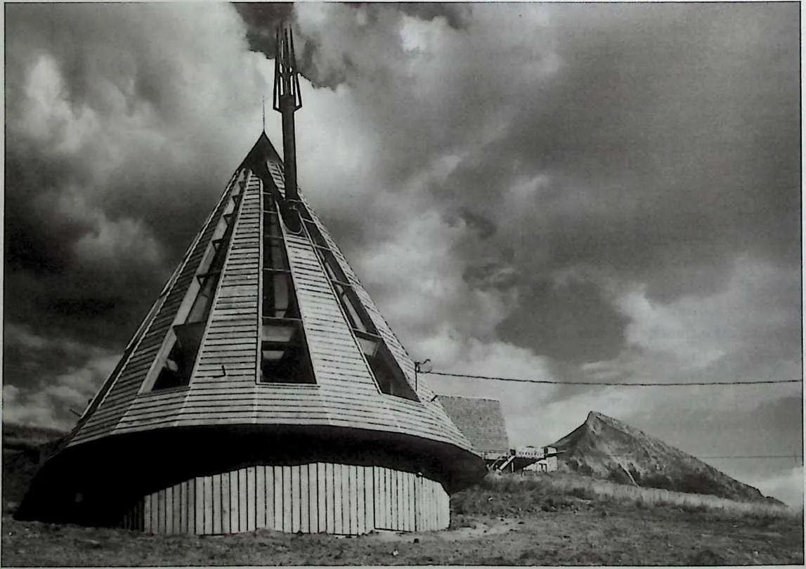
774775Figure 2.49 Ski Lodge, Crested Butte, Montana, 1965. Photo. (Courtesy of the Ryerson and Burnham Libraries of the Art Institute of Chicago.)
776 approaching a cone) and Goff’s Hopewell Baptist Church, Edmund, Oklahoma, 1948 (Figure 2.50).
777 Philip Johnson’s Crystal Cathedral, 1980, Garden Grove, California (see Chapter 5), with its massive space truss walls and roofs, does not appear to be directly influenced by the Crystal Chapel, other than in its ‘‘crystallinity’’ and in the fact that Johnson was aware of Goff’s design.
778 Similar to Johnson’s Crystal Cathedral in its use of an all-encompassing space frame with pyramidally faceted glazing is the BioSphere 2 designed by architect Phil Hawes, both Wright apprentice and Goff student. BioSphere 2 utilizes a commercially available space truss throughout, enclosing just about everything—biological habitats, offices, and mechanical equipment—as Goff enclosed both of his major plan functions—the Crystal Chapel and its multipurpose wing—with the same rhombic envelope. (An example of an architectural precursor of an all-encompassing envelope is Paxton’s prefabricated glass.) In the BioSphere 2 in the late 20th century, the transparent structure has come full circle from the mid-19th century—back to its use as a ‘‘palm furnace.’’
779 R. Buckminster Fuller and Shoji Sadao’s Tetrahedron City project at Yomiuriland, near Tokyo, 1970, was a megadream proposed perhaps more for the sake of publicizing prototypical possibilities than for its communal perfection. The glass-clad spherical space frame of Fuller’s U.S. Pavilion at Montreal’s Expo ‘67 could be considered a ‘‘perisphere’’ to the Pyramid City ‘‘trilon.’’ Although Fuller’s continuous presence hovers patently over all ‘‘three-dimensionally triangulated’’ structures of whatever-hedra, it does not,
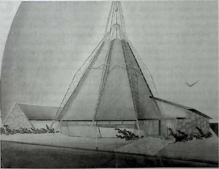
781 Figure 2.50 Hopewell Baptist Church, Edmund, Oklahoma, 1948. Rendered perspective. (Courtesy of the Ryerson and Burnham Libraries of the Art Institute of Chicago.)
782 in my opinion, establish hegemony over the Crystal Chapel.
783 LM. Pei’s pyramidal addition to the Louvre, an ultimate in mansard roofs (as Egyptian pyramid follows mastaba), and its smaller companion octahedra, are glazed with rhombi—similar to the Crystal Chapel. His Rock-and-Roll Hall of Fame, Cleveland, 1995, contains much larger but less elegant pyramidal elements—Miesian interpretations of the pyramid.
784 The black pyramid of the 2,500-room Luxor Las Vegas Hotel—with its layer of rooms hugging the exterior walls and appropriately straddling the River Styx—is a gaudy geometrical Goliath that runs rampant over history in yet a further display of the American (or perhaps just human) love of the buck and yet another lurch in the mindless romantic exploitation of the pyramidal past.
785 Several other recent entries in the pyramid sweepstakes are Moshe Safdie’s 1988 Canadian National Gallery in Ottawa and ‘‘Pyramid City’’ for 100,000 byTRY2004.51
786 The Jones Memorial Chapel as finally built at the University of Oklahoma, over protests from many prominent architects praising Goff’s project, is timid, conformist, and prosaically neo-Georgian. Philip Johnson was, incidentally, among those who protested.52
787 Vernon E. Rudd House, Projects, San Mateo, California, 1959–1962
788 In the three unbuilt designs for the Rudd House, the prominent polyhedral features are the bedrooms, individually attached ‘‘like melons on a vine,’’ as Goff put it, to an S-curve of corridor and common living areas (Figures 2.51 to 2.53 show Schemes 1 to 3, respectively). Their heritage includes Wright’s Usonian house concept with its linear arrangement of bedrooms on a long corridor; however, in the Rudd House the individual chambers are completely separated—surrounded by their own open space—like pavilions or cabins.53 If ‘‘polyhedral privacy pods’’ (my terminology) is too hard to take, I would suggest ‘‘truncated tetrahedral sequestration receptacles’’ or ‘‘individuated icosa-hedral enclaves.’’ The possibilities have yet to be explored—polyhedoir? poly-hedranctum? icosahedriculum? tetratorium? Goff did not shrink from exploratory terminology—he called his house for the Dewlins (a design that, incidentally, did not include polyhedra) an ‘‘aparture.’’
789 In the first version of the Rudd House, truncated tetrahedra (Figure 2.51 a-c) were used as bedrooms hung from cable and mast to keep them clear of the rough, wooded site. Scheme 2 kept the truncated tetrahedra but mounted each of them on six short legs (Figure 2.52). Contrast this Scheme 1 polyhedra—the geometry of the truncated tetrahedron54—with the (slightly modified) icosahedron—one of the five Platonic solids, used for the same purpose in Scheme 3 (Figure 2.53zz-e).
790 The ‘‘icosa-pods’’ of Scheme 3 rested on and were lifted above the irregular grade on short trunks (Figure 2.53ZJ. These raised units are a modest reminder of the late California architect John Lautner’s spectacular 1960 Malin House (‘‘Chemosphere’’)—an entire house, not just a room, octago-
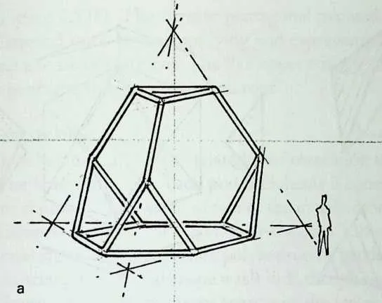
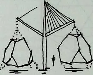
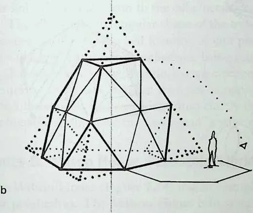
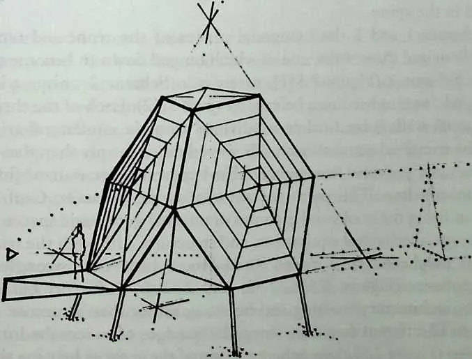
793 Figure 2.51 Rudd House, Scheme 1. Truncated tetrahedron units. Theoretical Vierendeel structural frame, similartothatof the Wilson House unit; (b)triangulated panels of the hexagonal faces, one of which hinged down to create an open porch.
794 Figure 2.52 Rudd House. Scheme 2. Truncated tetrahedron with six legs and triangular hinged-down porch.
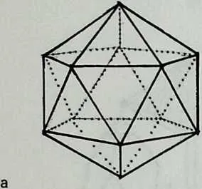
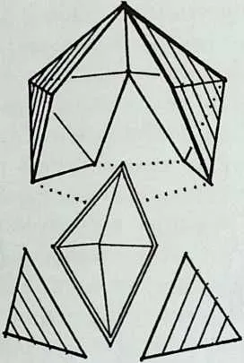
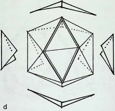
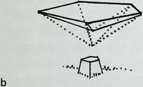
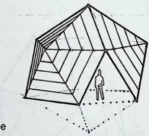
797 Figure 2.53 Rudd House. Scheme 3. Icosahedron units: (a} Icosahedron; (b) exploded view; (c) ‘‘cat's-eye’’ window; M4-symmetry aspects of the icosahedron; pentagons emphasized by paneling pattern.
798 nal in plan, perched on a very tall concrete stem to accommodate a steep slope in the Hollywood hills. Each o£ the Rudd pods was connected to the house corridor with a short prismatic passage. Bathrooms and storage were contained in the spine.
799 In Schemes 1 and 2 the hexagonal planes of the truncated tetrahedra served as floor and three walls, one of which hinged down to become an open terrace in Scheme 1 (Figure 2.51£), whereas in Scheme 2 only a triangular panel hinged down to become a balcony (Figure 2.52). Each of the three sloping hexagonal walls were further subdivided into six equilateral triangular panels. The truncated-tetrahedron walls sloped more steeply than those of the icosahedron and provided less comfortable headroom per unit of floor area than the icosahedron. This point is somewhat moot, however, Goff being a master at utilizing the nooks and crannies of unusual geometric spaces for furniture, storage, mechanical equipment, and structure. Although the triangulation of the polyhedral faces in the Rudd House bedrooms strongly recalls Fuller’s geodesics (Figures 2.5lb, 2.52, and 2.53*?), Goff’s principal thrust seems to be architectural massing and function, rather than structure.
800 Slices in 12 different directions through the edges of an icosahedron result in pentagons (Figure 2.53a). In Scheme 3 one of these slices became the floor
801 (Figure 2.53). The inverse pentagonal pyramid under this slice of floor was flattened out—thus simplifying and expressing the floor structure and creating a sense of platform. The five upper triangles of the icosahedron comprised a pentagonal pyramid pitched roof.
802 Fenestration
803 In Schemes 1 and 2 the triangles of truncation served as windows and doors. The fenestration for each pod of Scheme 3 consisted of a single bold lozenge (or rhombus, composed of two of the icosahedron’s equilateral triangles). This diamond-shaped ‘‘cat’s-eye,’’ half-window, half-skylight, gave the pod a personal signature beyond just polyhedron or geodesic (Figure 2.53c). This double-triangle diamond shape was a link, though not further utilized in the Rudd House, to the 4-symmetry aspects of the icosahedron, that is, the symmetry that links the icosahedron to the cube/octahedron family (Figure 2.53c).
804 The slightly more angular shape of the truncated tetrahedron imparted a stronger sense of individual identity, of unit presence, than the icosahedron. On the other hand, the icosahedron, being roundish, being perhaps a more familiar geometric solid to some, having more equitably distributed and smaller surface facets (the smaller triangles as opposed to the truncated tetrahedron’s hexagons), and so fitting more closely the curved circulation areas of the house—all this gave the ‘‘icosa-pod’’ a sense of repose and appropriateness.
805 James D. WSHsomi Mouse, Pensacola, Florida, 1950
806 The Wilson House (Figure 2.54) was an example of Stage 4 (multicelled regular polyhedra). The Wilson House cells were cubelike and, in fact, conveniently called cubes: ‘‘A cube module of 14 ft. was used, so that the space in each unit is intimate and is easily expandable. This was the first use of a three dimensional module in this way.’’55
807 As stated in Progressive Architecture:
809810A cube 14 ft on a side is the space module of which this entire house is composed. Each of the modular spaces is sufficiendy intimate for one or two people, yet added together they provide an appropriate space for large-scale entertaining. Each cube is framed in welded boiler tubing. Clipped to the framing are prefabricated redwood-faced wall panels, similar in appearance inside and out. The beveled corners have been filled in with glass jalousie units to provide cross ventilation and a sense of spatial continuity. Corrugated translucent plastic panels at the roof-line provide additional light.56
811 They were nevertheless ‘‘beyond the cube’’—truncated cubes, to put it in the simplest of terms. However, to see the Wilson House modules only as cubes with truncated edges (and corners; if not for the comer truncations, the edge truncations would produce elongated hexagons rather than rectangles—see Figure 2.55a) is to miss a number of subtleties.
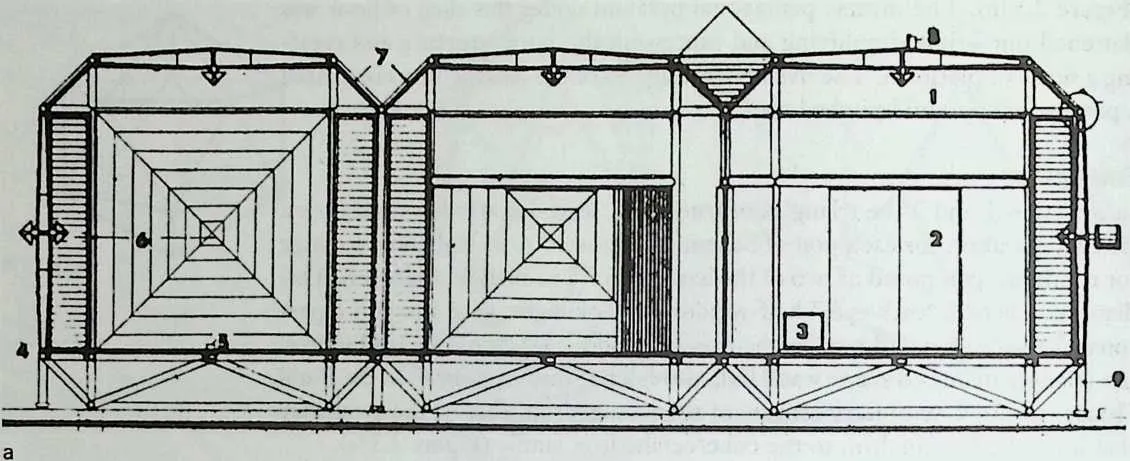
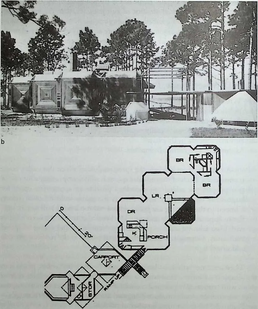
814 Figure 2.54 James D. Wilson House, Pensacola, Florida, 1950. fajSection; exterior photo; (c) plan. (Courtesy of the Ryerson and Burnham Libraries of the Art Institute of Chicago.)
815 c
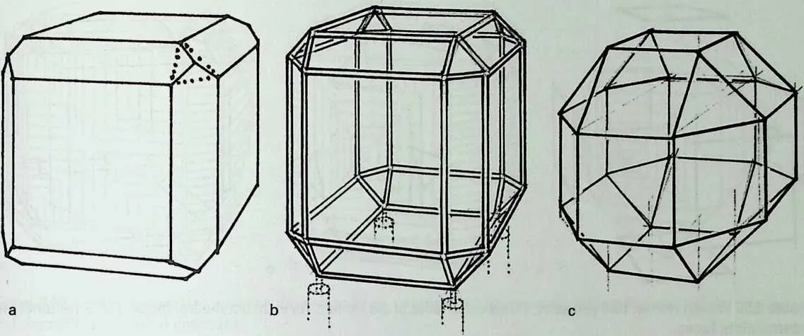
817 Figure 2.55 Wilson House, (a) Edge-truncated cube; (b) pipe frame module; (c) Rhombicuboctahedron.
818 The modular floor plan of the Wilson house, entrance, and carport consisted of a dozen abutting truncated squares. In plan, the modules defined the various functions, for example, living, dining, sleeping, and carport, whereas four truncated corners together provided services—fenestration, column locations, a fireplace, sliding doors, and circulation. The plan units were translated into three-dimensional modules (‘‘close packed’’—somewhat like a tray of muffins), which define and enclose the space within the house. L. Lines refers to closely packed polyhedra as ‘‘parallelohedra…. Congruent polyhedra that can be stacked together so as to fill space completely….’’57 This definition applied only very loosely to the Wilson and Pollock/Warriner houses—in the Wilson modules there were gaps left between, and in the PoHock/Warriner the modules overlap.
819 The Wilson module exemplified the creative possibilities of prefabricated production for architecture—an idea that reappears occasionally and seems to go nowhere—for example, during World War H and later with Operation Breakthrough in the 1960s. Prefabrication of the Wilson modules was more in the symbolic sense, as there was considerable on-site fabrication.
820 The generation of the Wilson module can be described in several ways as:
- 1.
- Truncation. An edge-and corner-truncated cube (Figure 2.55).
- 2.
- Dual transformation. Dual transformation of either a cube, an octahedron, or a rhombicuboctahedron (Figure 2.55c).58 The face planes enclosing the Wilson module consist of:
8238246 square cubic faces (Figure 2.56a)
8258 triangular octahedral faces (Figure 2.56b)
82612 rectangular intermediate faces (Figure 2.56c)
827If the design is seen as an RCO transformation, the octahedral edges and faces become reduced, and the intermediate faces, which would
830831Figure 2.56 Wilson House. Unit geometry: (a)s\x cubic faces of the module; (b) eight octahedral faces; (c) 12 rectangular intermediate faces.
832have been square in the initial RCO, become rectangles. Dihedral angles remain the same. Other ramifications of such a transformation can be seen in the Wilson module.
8333. Tesseract. The double-edged effect of the Wilson module resembles one of the possible three-dimensional projections of a tesseract—that curious four-dimensional relative of the cube, which is illustrated and discussed at some length by Bragdon.59
834 Each geometric component of the Wilson module was assigned a specific architectural function, as follows:
835 Edges. The edges of the RCO module were structural, consisting of 4-inch-diameter boiler pipe (Figure 2.55£). The joints (vertices) were welded, creating a kind of three-dimensional Vierendeel truss. The geometry necessitated welding because RCO geometry does not have the inherent stability of triangulation (even though the corners are triangles).
836 One of the RCO modules was left unclad and open, with the pipes describing the edges of its volume. This particular unit performed a multitude of tasks: It illustrated the module’s abstract geometry, contrasted with the enclosed bulk of the rest of the house, supported the carport roof, and served as an entrance totem.
837 Cubic Faces. On the exterior, the cubic faces dominated the transformed RCO module in size, pattern, and texture (Figure 2.56a and 2.57). Prefabricated wood siding ‘‘membranes’’ were intended originally for both walls and roofs, with the boards lapped in a series of nested squares—both inside and out—recalling the Wright trademark and its Chinese, Japanese, and Native American precedents. If, instead, the siding had been applied at 90° to the pipe frames, forming a cross pattern, it would not have emphasized the square face
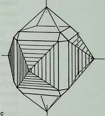
839 Figure 2.57 Wilson House. Unit paneling: (a) perpendicularto pipe frame (theoretical); (b) paneling as built; theoretical rhombidodecahedral dynamics.
840 and would have fought with the corner jalousie window lines (Figure 2.57 a). Nor would the overlap of the boards have fit properly against the pipe frames. On the interior of the house, the nested squares regulated the dimensions of doors and other openings.
841 Having been designed originally for a California hillside site with an approach from above, with an identical pattern on the roofs of the modules as well as their sides, the house would have read clearly as a cluster of three-dimensional units. The units would become ‘‘supercubes,’’ as it were, in spite of their RCO characteristics, that is, each of the geometric elements of the cube—corner, edge, and face (i.e., point, line, and plane—which Goff emphasized in first-year design courses) being articulated and emphasized in its own right.60
842 Redwood siding was to have been used in California. When the Wilsons retired instead to Florida, Goff changed the design to cypress—but none was available—so he stayed with the redwood; however, on the flat Florida site because the roof surface was not visible a conventional built-up tar-and-grav-el roof was used. As built, the interior of the module had equivalent side and ceiling surfaces—on the exterior, only equivalent sides.
843 Another interpretation of the pattern of nested squares of wood siding is that they symbolize the stages of transformation through which a rhombicuboctahedron might pass on its way to becoming a rhombidodecahedron, thus energizing and reinforcing polyhedral spatial presence and implying movement and change (Figure 2.57c).
844 Upper Sloping Planes and Triangles. The long, narrow upper sloping intermediate planes of the RCO and the upper comer, triangular, octahedral faces held fixed translucent glass fiber clearstorys (Figures 2.56c and 2.57 b).
845 Vertical Rectangles. These rectangles contained glass jalousie windows, which were sandblasted for privacy in two bathrooms (Figures 2.56c and 2.57b).
847848Lower Sloping Planes and Triangular Faces. These components were opaque—cement asbestos board, comprising an apron that concealed the crawl space between the floor deck and grade (Figures 2.56b and c and 2.57ti).
849Rex Slack, another Goff student, did additional drawings on the site as needed and supervised the construction along with fellow student Ray Cobb. Unseen in the completed house and, in fact, not on the working drawings, according to Slack, were short, stub pipe columns on which the larger RCO units rested (Figure 2.55Z>), necessary for anchoring to footings and leveling—the stub pipes being concealed by the gentle slope of the gravel grade near the house. Some of the upper pipes were slotted to serve as gutters. Slack said that there had been some condensation on the interior faces of some of the pipe frames but he knew of no roof leaks. Larry Grantham visited the site in 1982 and observed that ‘‘pipes were rusted through at the horizontal roof areas. Roof leaks were subject to continual maintenance. There could have been many years without problems, though. One of the typical problems, needless to say, with these perfect geometric concepts is that such planes create difficult to impossible places to fabricate without leaking problems. Something to be considered by students….’’
850The occurrence of the plane of the floor inside rather than on the surface of the RCO module characterizes a common concern in adapting pure geometric solids such as polyhedra and geodesics to architecture, that is, the need for flat circulation areas accompanied by human-scaled headroom. The plane of the floor intersected the Wilson modules at the bottom edge of the large square wall membranes, permitting significantly more usable floor space (by getting the canted triangular corner pieces and their connecting frame members out from under foot) than had the floor level been at the lowest square face (Figure 2.58). This created a crawl space, which contained floor bracing plus the usual mechanical and electrical necessities. It caused the exterior and interior expressions of the RCO to differ somewhat. Whereas the exterior read clearly as a set of modules, the interior, although still retaining the modules, appeared as a grove of abstract tree trunks and branches.
851Other elements of the house interacted with the RCO module as inter- penetrations (e.g., a pool and a four-way fireplace) and as variations (light fixtures, folding doors, and shed roof). The fireplace chimney was capped by an ornamental octahedral sculpture—to symbolize a free passageway for smoke?
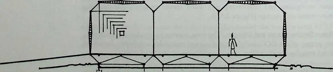
854855Figure 2.58 Wilson House. Schematic section.
856The Wilson House was destroyed by fire in the 1980s. The present owner, an architect, cut up and reassembled the frames, using the original floor structure—but it is entirely different now, according to Grantham.
857The Donald Pollock [House, Oklahoma City, 1957, Remodeled by Goff for John and Laura Warriner, 1977
858 The Pollock/Warriner House (Figure 2.59), like the Wilson House, is based on adjacent, repeated polyhedra derived from a floor plan consisting of abutting truncated squares; however, the joining of the Pollock/Warriner
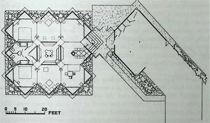
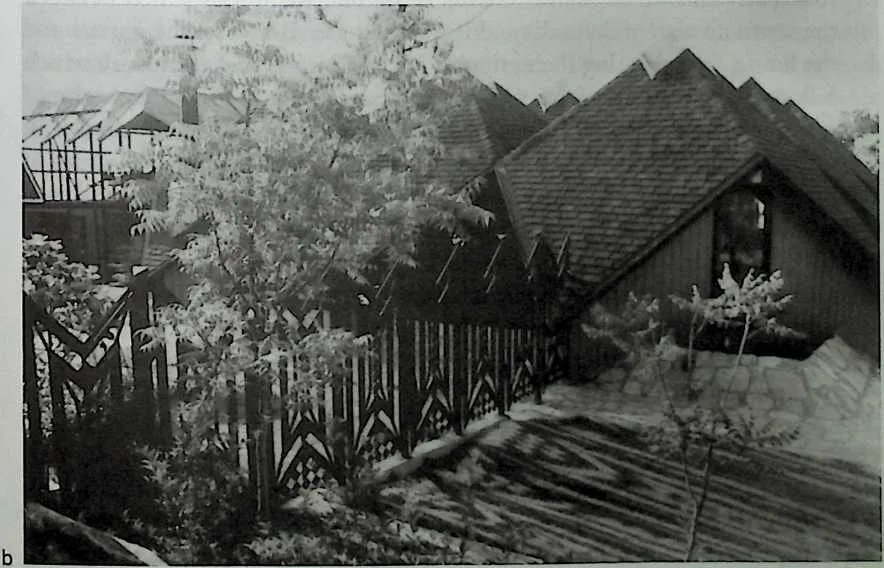
861 a
862 Figure 2.59 Pollock/Warriner House, Oklahoma City, Oklahoma, 1957. (a) Plan; (b) photo.
864865modules is more complicated. Like the Wilson module, the Pollock/Warriner module can be depicted as having been generated in several ways. Of these, incidentally, the most likely involves a design process that probably did not start with the polyhedra that we see in the completed house.
866To give an overview of the Pollock/Warriner House, we turn to others:
867De Long writes, ‘‘In plan, nine interlocking squares are arranged symmetrically upon a large square plinth. Nine pyramidally shaped roofs, each with an individual skylight at the peak, give volumetric expression to the module. In this realized design, shingles laid along angled lines further emphasize a crystalline quality, as do the faceted panels of translucent plastic over a porch joining house and garage. As with the McCullough and Bass projects [discussed previously], the parents’ and children’s areas are clearly defined along extremities of the house, and are joined by centrally placed units. And like the Wilson house of 1950 [discussed previously], the implied grid imposed by the strictly applied module disciplines the open interior.’’ Beginning in 1980, Goff made interior changes for later owners, Paul and Laura Warriner, who, De Long says, ‘‘became strong supporters of Goff. Their commissioned alterations included the addition of a swimming pool and cabana, as well as an elegant interior remodeling…that reinforced the plan’s clarity.’’61
868Architectural Design describes the Pollock house as being
869based on a plan of nine interlocking squares surmounted on a battered stone base—also in the form of a square. Each of the smaller squares is covered with a pyramidal roof, the sawtooth fascias of which echo the plan. A pyramidal skylight is positioned at the peak of each roof. The roofs, notes De Long, are covered with wood shingles which were originally painted dark green—the vertical siding of the wood-framed structure is painted fight green. At each interlocking corner of the squares are narrow full-height windows overlooking triangular planters formed between the sawtooth plan of the walls and the stone base. Between the garage and the house, and spanning the entrance, is a large screened enclosure which follows the geometry of the rest of the house, but on a slightly reduced scale, and slightly taller. This structure is wholly glazed and finished with pyramidal formed, translucent, green plastic roof panels. The structure of this outdoor living area encompasses part of the garage roof which is used as a sun-deck. Inside, the house is organized around a central kitchen (at Mrs. Pollock’s request) and divided into various spatial configurations by accordion doors. Against Goff’s advice the Pollocks commissioned landscape architects who repeated the 45° geometry of the plan in a hard-edged pattern of planting areas.’’62
870The polyhedral module of the Pollock/Warriner House is the rhombidodec- ahedron (occasionally referred to below as ‘‘RD’’), which has 12 rhombic faces (Figure 2.60zz). It is, incidentally, the dual of the cuboctahedron—an Archimedean solid.
871The plan schemata starts with nine 13-foot truncated squares arranged in a three-module-by-three-module grid, each square anchoring a major func-
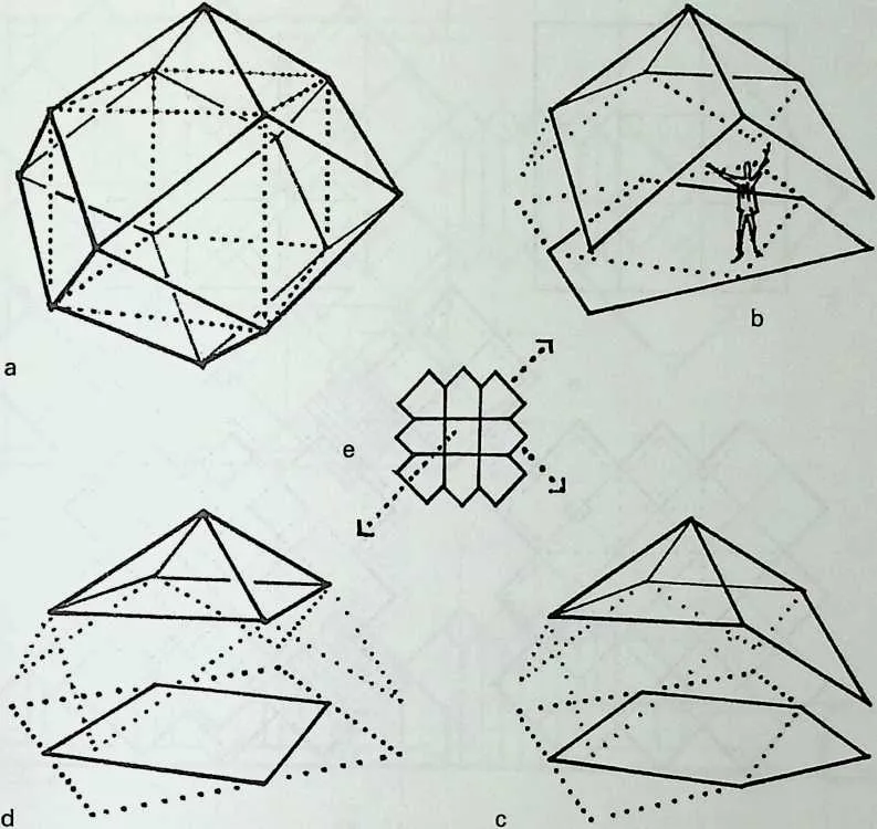
873 Figure 2.60 Pollock/Warriner House. Rhombidodecahedral unit geometry:
- (a)
- rhombidodecahedron relative to inscribed cube;
- (b)
- typical corner unit and plantrace; fc/typical edge unit and plan; (d) interior unit and plan; (e) schematic roof plan key.
875 tional area, for example, living, dining, and bedroom (Figures 2.59a and 2.61a).
876 Truncations of the comers of the grid squares form smaller squares (with 4-foot diagonals) at 45° to the original larger squares (Figure 2.61b). These areas, again as in the Wilson House, serve as circulation nodes, column locations, and window and door frames. Other elements in the house occur in harmony with the scale of these truncations, for example, skylights (one at the peak of each pyramid, recapitulating in miniature the RD shape of the roof below), distance of floor level to low point of roof, and screened porch mullions.
877 The truncations are extended at the exterior walls until they meet, forming the edges of yet another group of squares (about 16 feet) at 45° to the original group of squares and overlapping one another (Figure 2.61c). These new 45° ‘‘outcroppings’’ expand the original squares to provide storage, seating, dining, and bathroom space around the perimeter of the house. This group (discounting the roof overhangs) comprises plan sections of partial rhombidodecahedra.
878 The Pollock/Warriner module is related through transformation to the tetrakis hexahedron (Figure 2.62a) and the triakis octahedron (Figure 2.62b)— stellation-like derivatives of the cube and octahedron, respectively. They would not have played a part in the generation of the design, although the ‘‘stellation’’ aspect of the ‘‘outcroppings’’ mentioned in the preceding paragraph invites comparison.
879 The cluster of pitched-roof rhombi are the primary expression of these
880 Figure 2.61 Pollock/War-riner House. Development of plan grid: (a) square grid; (b) corner truncations; (c) truncations extended to form another grid at 45°; (d)roof plan; (e) rhombidodecahedral roof plan unit.
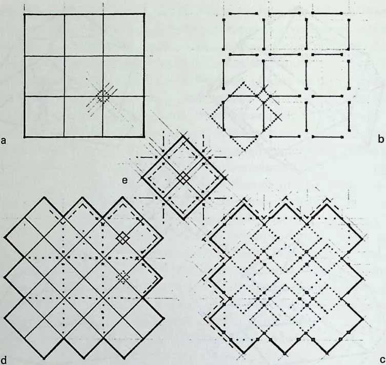
882 RDs, with half-and quarter-rhombi comprising exterior walls (Figures 2.61c and d and 2.63). However, nowhere is an entire 12-faced rhombidodecahe-dron completed. If it were, the obvious problem of how to provide a flat floor would occur. As to the roofs, the working drawings referred to them simply as hipped roofs, and so they are. They are similar to the ‘‘helm’’ roofs of Romanesque bell towers (e.g., Limburgh, Cologne, and Speyer Cathedrals), though the rhombi of these roofs are much more elongated than the Pol-lock/Warriner module (Figure 2.64). The central portion of the Crystal Chapel is a triangular version of the helm roof (Figure 2.46).
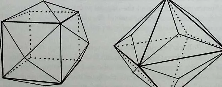
884 b
885 Figure 2.62 Pollock/War-riner House. Related geometry: (a)tetrakis hexahedron; (b) triakis octahedron.
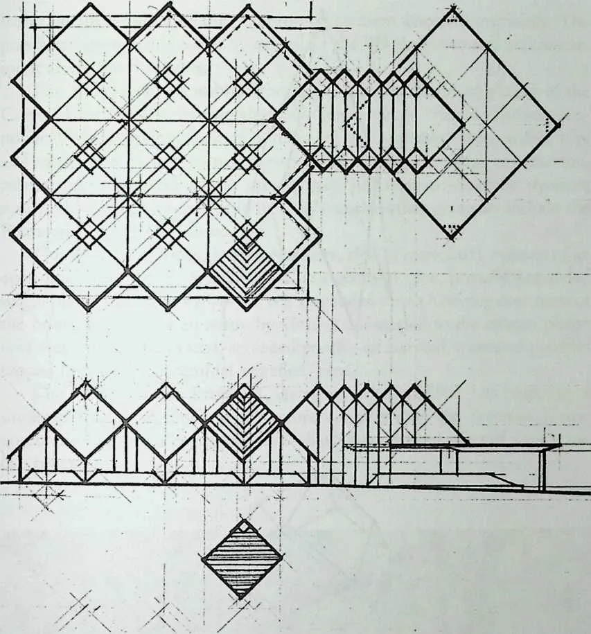
888889Figure 2.63 Pollock/Warriner House. Roof plan and elevation.
890 The ceilings under these hipped roofs rise to 15 feet at the top of the skylights and to just under 3 feet at their low points. The lower areas are consigned to the backs of closets and alcove-like portions of seating areas, with the underside of the main 4x10 beams at a height to accommodate a conventional 6-foot, 8-inch wood folding door.
891 The axial, or orthographic, projections of an RD are square grids (Figures 2.6\d and e and 2.63). A ‘‘4-axis’’ is that projection onto a plane that is perpendicular to an axis through opposite vertices at which four edges meet. The actual face angles, however, are 70° 32' and 109° 28'—hence the ‘rhombi’ in rhombidodecahedron.63
892 This square projection appears in both plan and elevation of the polyhedra and in the design and working drawings of the house—and the actual roof slopes are 45°. Looking at the drawings, an unsuspecting builder might not be aware of the rhombus nature of the roof segments until construction was underway. An untoward effect would be the fact that plywood sheathing would not fit as neatly on the rhombi as onto 90° rectangular shapes. The original
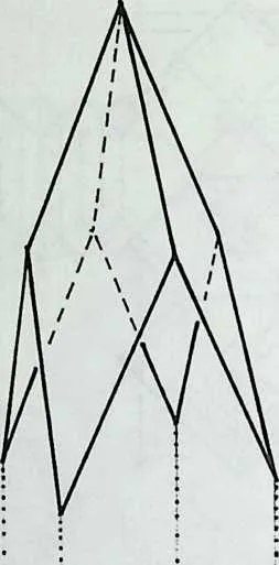
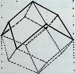
895 Figure 2.64 Pollock/Warriner House. Unit roof compared to medieval ‘‘helm’’ roof.
896 shingle pattern of nested V’s, which followed and emphasized the rhombi’s lower edges (a counterpart to the nested squares of the Wilson House redwood siding) was long ago replaced with conventional horizontal rows of shingles, eliminating one of the strong echoes of the RD profile (Figure 2.63).
897 A rhythm is created by the Pollock/Warriner House modules by three identical geometric shapes. Similar triplets occur in other Goff works, for example, the square faces of the Wilson House and the dodecagons of the First National Bank, among many others. The repetition of the regular faces of polyhedra or other structures symbolizes rationality—but in Goff’s work it also creates ‘‘music’’—rhythm.
898 The simplicity of the flat-roofed, corner-truncated, square-on-a-45°-angle garage contrasts strongly with the sculpted cluster of rhombi of the main house and is derived from the plan module formed by the roof ridges (Figure 2.63). The two are joined by a translucent green corrugated glass-fiber-roofed, screened porch that is a transparent, crystalline variation of the RD based on the module of the truncation dimension discussed previously. The porch variation is arrived at by extending the RD along two axes and repeating it along the third axis.
899 The translucent rhombi of the porch echo the diamond glazing of the Crystal Chapel. Effective polyhedral volumes can be created relatively economically in elements such as porches by means of inexpensive screen wire and ribs. The requirements of structural design, detailing, construction, weatherproofing, and so on are simpler and cheaper. Spatially dynamic screened porches are frequent in Goff’s work—other examples include the Freeman and Miller Houses.
900 The Freeman House, Joplin, Missouri, 1958 (Figure 2.65), consists of an open-plan, rectangular space roofed by a gently sloping, partially suspended single plane. The roof expressed as a suspended carpet hovering over most of the house was used frequently by Goff. A counterfoil to the opaque planar roof element is an elevated, screened porch—an inverted, truncated pyramid topped by another pyramidal screened ‘‘roof.’’
901 The Miller House, Project 3, Harrison, Arkansas, 1963, was topped by a similarly spatial screened porch, more complex than the Freeman House porch and built on a hexagonal plan—having the faceted effect of a cut stone in a setting.
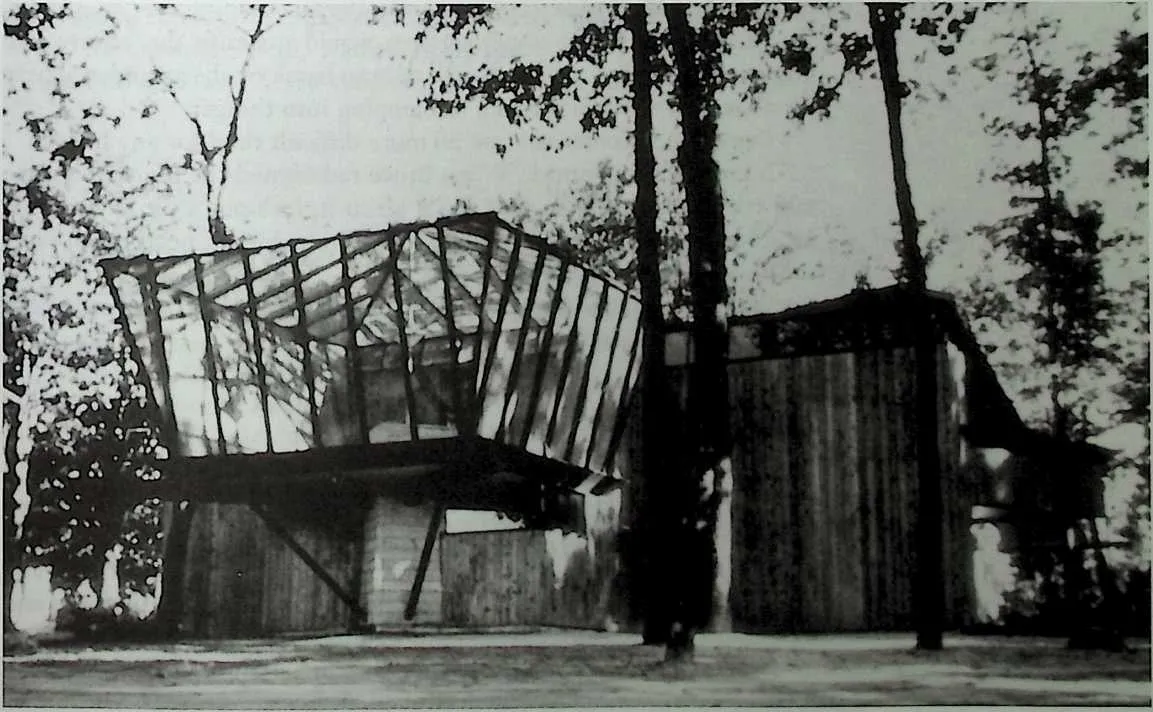
903 Figure 2.65 Freeman House, Joplin, Missouri, 1958. Photo of screened porch. (Courtesy of the Ryerson and Burnham Libraries of the Art Institute of Chicago.)
904 Frank Lloyd Wright frequently increased the sense of space and size in his designs with the comparatively economical use of porches and carports, which extended axes and elongated ground-hugging planes and masses.
905 The composition of the Pollock/Warriner House involved three major elements: (1) the cluster of roof polyhedra of the main house, (2) the flat-top garage, and (3) the polyhedral variations of the screened porch. The interaction of these three components, along with their exterior/interior spatial complexities and the attention to color, material, and detail, results in a grandeur, an atmosphere beyond the modest size, material, and construction methods of the dwelling.
906 Dr. and Airs. Warriner were asked to describe how it felt to live in this house—with emphasis on the polyhedral aspects. Laura Warriner, a painter, said:
908909I could never live in an ‘‘ordinary’’ house. The forms of light and shadow in this house are an education. It feels like living in a giant palace. It amazes people when I tell them it’s only 1,500 square feet. It was confusing when I first moved in—maze-like. …It’s amusing to see peoples’ reactions to the house when they first come in.
910The light changes during the day because each room has its own skylight. Thunderstorms—the house puts you in tune to nature—die outside comes in (visually, that is)—you can see completely through the house. It’s like living outside—the sense of shelter. If it’s snowing it’s like snowing on you. It’s like being inside a cut diamond—the faceted light.
911I felt that [polished stone] surfaces would magnify the effect. The house is angular but it does not seem to have harsh or sharp angles. There are no problems with headroom or bumping into things.
912 Repairs and maintenance are no more difficult than for any house.
914915It is not hard to furnish. When Bruce redesigned the house for us he said every other house of mine has a pit in it, let’s put a pit in this one. Most houses have too much furniture. This one doesn’t need much but I still have too much. But mostly it has art…
916I’m sorry that everybody in the whole world can’t live in a Bruce Goff house!64
2.26 GOFF’S LEGACY
918Goff left a rich body of work both with and without polyhedrality. Some of these have been lovingly and carefully tended and preserved. Others have suffered neglect, emasculating alterations, fires, and demolition, and need public attention and nurturing. The Gutman and Wilson Houses and the Phi Lambda Fraternity House were demolished after damaging fires. Other Goff houses are gone—the Glen Harder House near Mountain Lake, Minnesota, was completely destroyed by fire recently. In December 1996, Goff’s masterpiece, Shin’enkan, the former Oklahoma residence of Joe and Etsuko Price, burned to the ground. Arson is suspected. The Frank Cole House in Park Ridge, Illinois, an example of Stage 1 polyhedrality, was demolished several years ago. A number of structures have undergone radical alterations, for example, the 1967 Mercedes-Benz Building in Atlanta.
919 ‘‘…The process of designating as landmarks many of his best designs has just begun, and will continue as the structures pass the 50-year mark required for official recognition. It is our hope that the remaining body of Goff’s extant designs will be recognized and preserved as a testament to one of America’s great architectural minds.’’65
920 Goff’s contribution to the use of polyhedra in architecture did not originate in a spirit of rigorous polyhedral form making. Rather, it translates the concepts of Bragdon, Wright, et al., by creating new transcendental environments, incorporating polyhedra in their place among the universe of architectural form/structure/space possibilities.
2.27 ACKNOWLEDGMENTS
922I would like to thank the following for their assistance: Robert Bowlby, Nelson Brackin, Susan Bresler, Ernest Burden, David De Long, Jean Eckenfels, Robert Faust, Jack Golden and the Friends of Kebyar, Larry Wayne Grantham, Herb Greene, Grant Gustafson, Randolph Helming, David Milstead, Mrs. James Nicol, Kathy Nicol, Bruce Nicol, Joe Price, Rex Slack, Laura Warriner, and Mary Woolever and the Art Institute of Chicago.
2.28 NOTES
- 1.
- For a comprehensive, ‘‘rich and definitive account of the life and work of the brilliant maverick from the western plains,’’ according to Helen Searing (whose 1996 Goff-designed house in Kansas City, Kansas, includes variations on extruded truncated hexagonal prisms), refer to David G. De Long, Bruce Goff. Toward Absolute Architecture, MIT Press, Cambridge, MA 1988.
- 2.
- Refer to Sidney K. Robinson, ‘‘Bruce Goff and Music,’’ in The Architecture of Bruce Goff, 1904–1982, Art Institute of Chicago/Prestel, 1995.
- 3.
- Examples of Goff’s buildings utilizing forms other than polyhedra include: the Ford/Robinson House, Aurora, Illinois, 1948 (torus, cone); the Bavinger House, 1950 (helix, cylinder); the Garvey House 1 project, 1952 (sphere, torus, helix); Sid Lodge, Crested Butte, Montana, 1965 (16-sided, polygonal pyramid approaching cone); and the Struckus House, Woodland Hills, California, 1983 (cylinder). In 1978 the Bavinger House was recognized with a ‘‘Twenty-Five Year Award’’ from the American Institute of Architects as an ‘‘extraordinary work of imagination …a vivid expression of American values.’’
- 4.
- For example, the undulating and ragged ‘‘free forms’’ of the Don Leidig House project, 1946, and the Ledbetter House, Norman, Oklahoma, 1947. Tension structures also occur in Goff’s output, e.g., the aforementioned Bavinger and Lei-dig Houses, the Plunkett Guest House project, the Shin’enKan Museum in Los Angeles, etc. Tension structures employ cables deployed in straight-line configurations. Both two-and three-dimensional arrays of cables occur in Goff’s work, in the latter case resulting in subtle geometric volumes—cylindrical, conical, pyramidal, etc. Tension arrays were often used ornamentally by Goff, frequently as ‘‘curve stitching,’’ i.e., the overlapping of a group of straight lines such that their intersections result in polygonal or curved shapes.
- 5.
- Many books illustrate and analyze these figures, e.g., Anthony Pugh, Polyhedra, A Visual Approach, University of California Press, 1976; Magnus J. Wenninger, Polyhedron Models, Cambridge University Press, 1971. The latter covers both regular and semi-regular polyhedra, or more generally, the 75 ‘‘uniform’’ polyhedra, including stellations.
- 6.
- Crystallographers study centers, planes, and axes of symmetry and the relative orientation of x, y, and z axes in minerals, using terminology such as ‘‘monoclinic,’’ ‘‘brachypinacoid,’’ and ‘‘orthorhombic.’’ A recent concern of crystallographers is the hypercrystal, which is an irregularly organized, quasiperiodic structure. See Chapter 15 for a discussion of quasicrystals.
- 7.
- Robert Lawlor, Sacred Geometry, Philosophy and Practice, Crossroad Publishing, New York, 1982, p. 104. Here is another source on polyhedra, ‘‘gnomonic expansion,’’ the spiral, the golden section, metaphor, and universal order, etc., with many good illustrations and diagrams.
- 8.
- John Sergeant, Architectural Design Profiles 16, p. 55.
- 9.
- D’Arcy Thompson, On Growth and Form, John Tyler Bonner, ed., Cambridge University Press, abridged Ed., 1966, p. 122. Bonner, a biomorphologist, is the author of Morphogenesis, An Essay on Development, Atheneum, 1963, which discusses three basic determinants of form in the biological world: growth, differentiation, and morphogenetic movement. As architectural metaphors, growth is cell (module) iteration or duplication; differentiation represents the functional variations of spaces such as living room, dining room, entry, and storage; and morphogenetic movement represents uniform characteristics carried throughout different parts of the same building, e.g., structural members, mechanical lines, and materials assemblies.
- 10.
- The startling architecture of the zoological world is revealed in Karl von Frisch, Animal Architecture, Harcourt Brace Jovanovich, 1974. This book covers habitations and devices actually built by animals, not the anatomy of the animals themselves.
- 11.
- A steel frame sculpture objectifies this abstraction in Venturi and Rauch’s Franklin Court, Philadelphia, 1972–1976. It is illustrated in Charles Jencks, The Language of Post-Modern Architecture, Rizzoli, 1984, p. 89.
- 12.
- For a capsule visual history of architectural form covering 111 ‘‘styles,’’ including a profusion of recent entries, in 25 pages, see Chap. 1 of Ernest Burden, Elements of Architectural Design, A Visual Resource, Van Nostrand Reinhold, 1995. For a capsule history of Goff’s work, see the graphic, multipage pull-out section—pp. 7–14—in I’Architecture d’Aujourd Hui, No. 227, June 1983.
- 13.
- Islamic ornamental patterns are illustrated and analyzed in Syed Jan Abas and Amer Shaker Salman, Symmetries of Islamic Geometrical Patterns, World Science, River Edge, NJ, 1995. The 17 unique symmetry groups are used as a basis for this study. Another source of clear graphic analysis of intertwining Islamic tessellation (not only in architecture, but in planning, poetry, and music!) is Issam E. Said and Ayse Parman, Geometric Concepts in Islamic Art, World of Islam Festival Publishing Co., London, 1976.
926927Grids related to the Islamic can be found in Kaiyama Kyusaburo, The Book of Japanese Design—Bansho Shin Hinagata, Bijutsu Oyo, Crown, New York, 1969. Two-dimensional patterns attempt to rise off the paper into the third dimension—some quite similar to Goff designs in the Price Studio. The three-dimensional metal curtain walls of Goff’s First National Bank are related to these patterns.
- 14.
- ‘‘The Architecture of Bruce Goff,’’ Architectural Design, May 1957, p. 151. Author and historian Park was the University of Oklahoma architectural school librarian during Goff’s chairmanship. Goff, incidentally, explaining the bland conformity throughout the profession, said, ‘‘We all read the same magazines.’’
- 15.
- Francine du Plessix and Cleve Gray, ‘‘Bruce Goff, Visionary Architect,’’ Art in America, Winter 1965.
- 16.
- See John C. Lilly, Programming and Metaprogramming in the Human Bio-Computer, Julian Press, 1972.
- 17.
- Mentioned in an interview with Johnson in Vanity Fair, June 1993, p. 157.
- 18.
- An increasing number of three-dimensional graphics programs are available for computers, e.g., Truespace. One can start with a polygon, drag (extrude) it to make a prism, shrink one end, see it in three dimensions, and rotate it—here is an embryo polyhedral unit of the Price Studio. Or one could call up a preformed ‘‘organic,’’ i.e., a single geometric volume and transform it by pulling it through a ‘‘deformation lattice’’ or ‘‘energy field.’’ Then one can apply a surface texture, shades, and shadows, etc. Artifice contains a ‘‘solid modeling program’’ in which a three-dimensional background ‘‘space’’ appears with the cursor attached to a ‘‘wireframe,’’ e.g., lines representing the x, y, and z axes, in perspective. Typical commands are ‘‘linear duplicate,’’ ‘‘wallify’’ and the like. Not to mention the ubiquitous Autocad and animation programs such as Lightwave and Video Toaster. Information can be obtained from Computer Chronicles Newsletter, 1–800–800–9520. See Chapter 12 for a discussion of computers and polyhedra.
- 19.
- Introduction to A Portfolio of the Work of Bruce Goff, designed and compiled by William Murphy and Louis Muller, Architectural League of New York and American Federation of Arts, 1970. For an elaboration of these ideas, see Herb Greene, Mind and Image, Ait Essay on Art and Architecture, University Press of Kentucky, 1976, and Building to Last, Architecture as Ongoing Art, with Nanine Hillard Greene, Architectural Book Publishing Co., 1981. The Greenes go on to say (in the latter, p. 77), ‘‘Nature seems patient of as many systems of geometries as we can discover. At this time who can say which warrants the highest metaphysical status.’’
- 20.
- Suzanne K. Langer, Feeling and Form, A Theory of Art Developed from Philosophy in a New Key, Scribner’s, New York, 1953, p. 99.
- 21.
- Le Corbusier’s treatises: Modulorl irll, Harvard University Press, 1980. For a discussion of the golden mean or golden section, the ratio 4>> i-e., 1:1.618…as inherent in certain polyhedra, e.g., the icosahedron and dodecahedron, see H. E. Hunt-ley, The Divine Proportion, A Study in Mathematical Beauty, Dover, 1970.
- 22.
- This taxonomic series could be continued with a similar grouping for curvilinear forms—first, extrusions of two-dimensional curves, then curves beyond the flat plane, i.e., spheres, etc., singly and in clusters—continuing further with combinations of spherical surfaces and polyhedral forms and finally ‘‘free forms’’ and beyond. A transition from the polyhedral to the curvilinear can be seen in polygons with increasing numbers of edges—but this is for another study. A number of Goff designs were curvilinear in the first go round and later revised to polygonal to fit the budget. Scaling down occurs with the Price Studio designs, but away from complex polyhedra rather than away from the curvilinear.
930931In his article ‘‘Bruce Goff, The Strict Geometrist,’’ in Architectural Design Profiles 16 (a special issue on Goff), John Sergeant divides Goff’s work into crystalline (with three categories—rectangular, diagonal, and triangular) and curvilinear (four categories—circular, radial, spiral, and processional).
- 23.
- For a discussion of depth cues, see James J. Gibson, Perception of the Visual World, Riverside Press, Cambridge, 1950.
- 24.
- As a student of Goff in the early 1950s, I felt that Goff was neither particularly interested in nor impressed by Fuller’s ideas, unlike a few of his students, myself included. Goff was, rather, politely respectful and appreciative of Fuller’s work, as he was with that of technologists such as 'Ibrroja, Candela, Nervi, and Maillart, to name a few.
934935The Louis Kahn/Ann lyng high-rise space frame office tower, part of Kahn’s Plan for Central Philadelphia, was well publicized at this time (mid-1950s). As a classroom assignment this writer attempted to design a ‘‘High-Rise Monastery for Downtown Houston,’’ incorporating living, circulation, and service spaces within a story-high tet-oct grid (i.e., a space frame whose structural members were composed of a ‘‘close packing’’ of alternating tetrahedra and octahedra).
936We also designed a Chinese restaurant using the Fuller/Kenneth Snelson concept of discontinuous compression in the form of a sphere, or, more accurately, a tensegrity-modulated icosidodecahedron, as a structural/envelope matrix. In both cases almost the entire time allotted for the projects was taken up just trying to figure out the projective geometrical drawing of these forms, which today would be a snap on the computer. A pentagonal prism core/mast of concrete containing vertical circulation, kitchens, mechanical equipment, etc., served and supported the tensegrity bubble, which enveloped and supported the dining platforms. Goff grasped the nature of the beast and was most helpful in overcoming problems for the utilization of these forms in an architectural setting.
937Just as a reminder of the typically strong effect Buckminster Fuller had on students across the country during the 1950s—another Goff student, New York architect Robert Tieger, says, ‘‘Fuller gave a talk at the O.U. Student Union. He talked on and on. The janitor wanted to turn the lights out at 10pm but Fuller went on ‘til about 12. It was the greatest thing I’d ever listened to.’’
- 25.
- De Long, Bruce Goff.
- 26.
- Michael Field and Martin Golubitsky, Symmetry in Chaos, A Search for Pattern in Mathematics, Art and Nature, Oxford University Press, 1992, p. 160.
- 27.
- The variety of space-filling polyhedral units and their manipulation via twisting, tipping, and other metamorphoses are explored in Donald G. Wood, ‘‘Space Enclosure Systems, The Variables of Packing Cell Design,’’ Bulletin 205, Engineering Experimental Station, Ohio State University, 1968.
- 28.
- De Long, Bruce Goff, p. 304.
- 29.
- Ibid.
- 30.
- Ibid., pp. 232–233.
- 31.
- Kathy Nicol, letter to author, August 25, 1995.
- 32.
- Architectural Design, May 1957, p. 173.
- 33.
- De Long, Bruce Goff, pp. 152–153.
- 34.
- John Sergeant, ‘‘Bruce Goff, The Strict Geometrist,’’ Architectural Design Profiles 16, Vol. 48, No. 10, 1978, p. 58.
- 35.
- Ibid. This article provides thumbnail illustrations of some two dozen floor plans on a single page (!) for comparison. Sergeant’s ‘‘crystalline’’ categorization of Goff’s work is mentioned elsewhere in this chapter.
- 36.
- The Lacey Hotel was, incidentally, a forerunner of a rhombic grid of glass cladding—recalled by Goff’s Crystal Chapel—although Wright’s diamonds were arranged in an overlapping shingle-like pattern, whereas Goffs were set flush within a supporting grid.
- 37.
- As illustrated in George T. Kerr, ‘‘Synthetic Zeolites,’’ Scientific American, July 1989. Zeolites are minerals composed of silicon or aluminum and oxygen molecules, which form truncated octahedra. A cross section through the center of a truncated octahedron is an octagon. This may provide a clue to the subtle yet complex sense of space imparted in the Jones House—that complex, repeating, spatial symmetries can be suggested by a few pieces of the grid.
- 38.
- For the full text of the letter, see De Long, Bruce Goff, p. 126.
- 39.
- This preceded by some years a scene from the sci-fi film Zardoz, in which Sean Connery is trapped within a magic gemstone. Note Mrs. Warriner’s crystalline comment near the end of this chapter.
- 40.
- De Long, Bruce Goff, p. 305. The quote within is from Herman George Schef-fauer, ‘‘Dynamic Architecture,’’ Dial, Vol. 70, March 1921, pp. 323–328.
- 41.
- Ibid., p.13.
- 42.
- For further descriptions of functions, see De Long, ibid., and Jeffrey Cook, The Architecture of Bruce Goff, Harper and Row, 1978, pp. 41–45.
- 43.
- Sergeant, ‘‘Bruce Goff.’’
- 44.
- De Long, Bruce Goff, p. 13.
- 45.
- James J. Gibson, Perception of the Visual World, Riverside Press, Cambridge, 1950.
- 46.
- See Dennis Sharp, Modern Architecture and Expressionism, Braziller, New York, 1966. An untoward side effect of some of these projects is the chilling recall of the Nietszchean mountain-climbing mystique in German films of the 1920s such as The Blue Light by Leni Riefenstahl, who later became a propagandist for Hitler.
- 47.
- Ibid.
- 48.
- Both illustrated in De Long, Bruce Goff.
- 49.
- The Sierpinski arrowhead, a sponge-like tetrahedral fractal, will probably be used sooner or later as a basis for high-rise office or apartment buildings, if it hasn’t already. The figure is illustrated in John Briggs, Fractals, The Patterns of Chaos, Discovering a New Aesthetic of Art, Science and Nature, Simon and Schuster, 1992, p. 68.
- 50.
- Reminiscent of the roof trusses of Goffs very low budget Hopewell Baptist Church, Edmund, Oklahoma, 1949. In this dodecagonal pyramid the subtlety of the basic ‘‘tepee’’ is increased by using over a dozen variations of the angle of the sloping roof—in walls, bell armature, truss chords, etc.
- 51.
- Safdie, ‘‘Pyramid City,’’ p. 90; Christian W. Thomsen, Visionary Architecture, From Babylon to Virtual Reality, Prestel Verlag, Munich, New York, 1994, p. 164. Several others in this book—Bruno Taut’s 1918 ‘‘The Crystal Mountain,’’ p. 81, and Wassili Luckhardt’s 1919 ‘‘Project for a Sacred Building’’ in concrete and colored glass, p. 85.
- 52.
- For Johnson’s comment about Goff’s Crystal Chapel, as well as high praise from other architects in support of the Crystal Chapel over a traditional period piece, see De Long, Bruce Goff, p. 104.
- 53.
- This has a spherical/helical counterpart in Goff’s first Garvey House.
- 54.
- At Expo ’67 in Montreal, multistoried truncated tetrahedra were constructed from space trusses for (appropriately) the Space Frame Exhibition Hall by architects Affleck, Desbarats, Dimikopolous, Lebensold, and Sise; structural engineers de Stein and Associates, Eskenazi, and Barass.
- 55.
- Architectural Design, Vol. 28, May 1957, p. 163. More on the Wilson House can be found in Sergeant, ‘‘Bruce Goff,’’ p. 22.
- 56.
- Progressive Architecture, Dec. 1962.
- 57.
- L. Lines, Solid Geometry, Dover, 1965. Lines illustrates close packing in polyhe-dra such as hexagonal prisms, ‘‘rhomboidal dodecahedra,’’ ‘‘rhombo-hexagonal dodecahedra,’’ and truncated octahedra—in order to prove properties relating to vertices, centers, etc.
- 58.
- See Haresh Lalvani, Transpolyhedra, Dual Transformations by Explosion—Implosion, Lalvani, New York, 1977. See also Chapter 14.
- 59.
- Claude Bragdon, Projective Ornament, Dover, New York, 1992, p. 28.
- 60.
- ‘‘Supercube’’ was a term used by Lester Walker, New York architect, teacher, and author, for a cubic device, totally different from the Wilson module, which he designed, patented, and built in the 1960s—a prefabricated, unfolding, expanding, ‘‘exploding’’ multipurpose studio furnishing module with a miscellany of built-in functions such as bed, desk, storage, and fighting.
- 61.
- De Long, Bruce Goff, pp. 154, 325
- 62.
- Architectural Design Profiles 16, p. 27.
- 63.
- Anthony Pugh, Polyhedra, A Visual Approach, University of California Press, 1976, p.43.
- 64.
- Laura Warriner, telephone conversation with author, 1994.
- 65.
- Annemarie van Roessel, ‘‘Bruce Goff’s Built Works,’’ in The Architecture of Bruce Goff, 1904–1982, Design for the Continuous Present, Pauline Saliga, Mary Wbolever, and Sidney K. Robinson, eds., Art Institute of Chicago and Prestel Verlag, 1995—the catalog issued in conjunction with the 1995 exhibition of Goff’s architecture and paintings at the Chicago Art Institute. The Institute holds Goff’s archives.
2.29 BIBLIOGRAPHY
940Abas, S. J., and Salman, A. S.: Symmetries of Islamic Geometrical Patterns, World Science, River Edge, NJ, 1995.
941 Baukunst und Werkform, No. 7, Frankfurt, 1953.
942 Bonner, J. T: Morphogenesis, An Essay on Development, Atheneum, 1963.
943 Bragdon, C.: Projective Ornament, Dover, New York, 1992.
944 Briggs, J.: Fractals, The Patterns of Chaos, Discovering a New Aesthetic of Art, Science and Nature, Simon and Schuster, New York, 1992.
945 Burden, E.: Elements of Architectural Design, A Visual Resource, Van Nostrand Reinhold, 1995.
946 Cook, J.: The Architecture of Bruce Goff, Harper and Row, New York, 1978.
947 Coxeter, H. S. M.: Introduction to Geometry, Wiley, New York, 1961.
948 De Long, D. G.: Bruce Goff, Toward an Absolute Architecture, MIT Press, Cambridge, MA, 1988.
949 Field, M., and Golubitsky, M.: Symmetry in Chaos, A Search for Pattern in Mathematics, Art and Nature, Oxford University Press, 1992.
950 Frisch, K. v.: Animal Architecture, Harcourt Brace Jovanovich, 1974.
951 Fuller, R. B.: Ideas and Integrities, A Spontaneous Autobiographical Disclosure, Robert W. Marks, ed., Collier Books, Macmillan, 1963.
952 Ghyka, M.: Geometrical Composition and Design, Alec Tiranti, London, 1952.
953 Gibson, J. J.: Perception of the Visual World, Riverside Press, Cambridge, 1950.
954 Goff, Bruce, Architect (boxed folio), distributed by Prairie School Press, Chicago, 1978.
955 Gray, C., and du Plessix, E: ‘‘Bruce Goff, Visionary Architect,’’ in Art in America, Winter 1965.
956 Greene, H.: Mind and Image, An Essay on Art and Architecture, University Press of Kentucky, 1976.
957 Greene, H.: Introduction to A Portfolio of the Work of Bruce Goff, designed and compiled by Louis Muller and William Murphy, Architectural League of New York and American Federation of Arts, 1970.
958 Greene, H., with Greene, N. H.: Building to Last, Architecture as Ongoing Art, Architectural Book Publishing Co., 1981.
959 Hambidge, J.: The Elements of Dynamic Symmetry, Yale University Press, 1919, reprinted 1948.
960 Holden, A.: Shapes, Space and Symmetry, Columbia University Press, 1971.
961 Huntley, H. E.: The Divine Proportion, A Study in Mathematical Beauty, Dover, 1970.
962 Jencks, C.: The Language of Post-Modern Architecture, Rizzoli, 1984.
963 Johnson, P.: Vanity Fair, June 1993.
964 Kerr, G.T.: ‘‘Synthetic Zeolites,’’ Scientific American, July 1989.
965 Kyusaburo, K.: The Book of Japanese Design—Bansho Shin Hinagata, Bijutsu Oyo, Crown, New York, 1969.
966 Lalvani, H.: Transpolyhedra, Dual Transformations by Explosion-Implosion, Lalvani, New York, 1977.
967 Langer, S. K.: Feeling and Form, A Theory of Art Developedfrom Philosophy in a New Key, Scribner’s, New York, 1953.
968 Lawlor, R.: Sacred Geometry, Philosophy and Practice, Crossroad Publishing, New York, 1982.
969 Le Corbusier: Modtilor I ir II, Harvard University Press, 1980.
970 Lilly, J. C.: Programming and Metaprogramming in the Human Bio-Computer, Julian Press, 1972.
971 Lines, L.: Solid Geometry, Dover, 1965.
972 Mohri, T.: Bruce Goff in Architecture, Kenchiku Planning Center Co., Tokyo, 1970.
973 Park, B. A.: ‘‘The Architecture of Bruce Goff,’’ in Architectural Design, Vol. 28, May 1957.
974 Parman, A., and Said, I. E.: Geometric Coticepts in Islamic Art, World of Islam Festival Publishing Co., London, 1976.
975 Progressive Architecture, Dec. 1962.
976 Pugh, A.: Polyhedra, A Visual Approach, University of California Press, 1976.
977 Robinson, S. K.: ‘‘Bruce Goff and Music,’’ in The Architecture of Bruce Goff, 1904–1982, Art Institute of Chicago/Prestel, 1995, catalog to the exhibition.
978 Scheffauer, H. G.: ‘‘Dynamic Architecture,’’ Dial,Vol. 70, March 1921.
979 Sergeant, J.: ‘‘Bruce Goff, The Strict Geometrist,’’ in Architectural Design Profiles 16, Vol. 48, No. 10, 1978.
980 Sharp, D.: Modem Architecture and Expressionism, Braziller, New York, 1966.
981 Thompson, D’A. W.: On Growth and Form, Abridged ed., John Tyler Bonner, ed., Cambridge University Press, 1966.
982 Thomsen, C.W.: Visionary Architecture, From Babylon to Virtual Reality, Prestel Verlag, Munich, New York, 1994.
983 van Roessel, A.: ‘‘Bruce Goff’s Built Works,’’ in The Architecture of Bruce Goff, 1904–1982, Design for the Continuous Present, Pauline Saliga, Mary Woolever, and Sidney K. Robinson, eds., Art Institute of Chicago and Prestel Verlag, 1995.
984 Wenninger, M. J.: Polyhedron Models, Cambridge University Press, 1971.
985 Wood, D. G.: ‘‘Space Enclosure Systems, The Variables of Packing Cell Design,’’ Bulletin 205, Engineering Experimental Station, Ohio State University, 1968.