
6 Tetrahedral Purity: The Javits Center
2Matthys Levy
6.1 INTRODUCTION
3New York’s Javits Center, one of the world’s largest exhibition spaces contained in a single building, sits on Manhattan’s waterfront on a 9-hectare site. Its distinctive architectural profile is identified by a unique space frame that both encloses and defines interior spaces. Because the center is a major public facility, the building’s architect, James Ingo Freed of Pei Cobb Freed, sought to create a design that welcomes the public while creating a dynamic interplay between the purely commercial and the public uses of the project. To achieve this result, Freed took advantage of the special features of the site: the views toward the river, the changes in ground elevation over the site, and the difference in relative importance of the surrounding streets.
6.2 ARCHITECTURE AND POLITICS
5The building is oriented along 11th Avenue, which slopes down from the southern to the northern end of the site, permitting the development of a two-level entry system. A ceremonial entrance at the highest point leads directly to a great entrance hall on the level of the upper exhibit hall. A roadway entered from the northern end provides access to a 300-m-long bus and taxi dropoff that is directly outside the concourse, which is at midheight between the two exhibit floors. The lower exhibit floor, with a 6-m ceiling height, contains about 60,000 m2 of space, including restaurants, meeting rooms, and a specialevents hall. The upper exhibit hall, with a ceiling height of 10 m and an area of 50,000 m2, is over 300 m long. A galleria floats above this hall in an east-west direction, providing access from the entrance hall to a future restaurant and bar overlooking the Hudson River. At the back of the exhibit halls, along 12 th Avenue, truck bays are provided on both levels with direct access to each exhibit floor.
6 The exhibit hall, the galleria, the concourse, and the entrance hall are all covered with a continuous space structure with a plan area of over 53,000 m2 supported on a grid of columns spaced 27 m on center. This roof structure climbs in giant steps from the general roof line over the exhibit hall to a point 47 m above the entrance hall. The multilevel cubes give the appearance of a crystalline structure reminiscent of the 1851 Crystal Palace.
7 New York had long sought to build a new convention center to meet the ever-growing demand of the public and trade show sectors that were inadequately served by the small (30,000 m2) coliseum. After a failed attempt in 1972, the needed legislation for a new center was passed in the spring of 1979 and married the state’s Urban Development Corporation, which had construction and planning expertise, to the Triborough Bridge and Tunnel Authority to provide the necessary financing. To further complicate matters, separate development and operating corporations were established to build and manage the new facility. This proved to be an awkward arrangement that was finally changed, centralizing all responsibility in one agency, but only after the building was completed.
8 GEOMETRY AND STRUCTURAL FORM
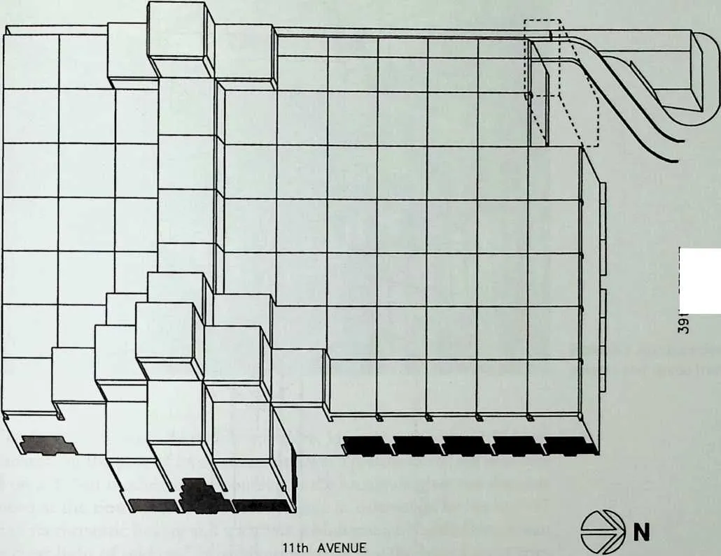
9 The two most challenging problems in the overall design were first to devise a structural system to unite the building’s diverse functions in a coherent pattern of visual and spatial rhythm, and, second, to articulate this structure in a way that visually reduced the scale of so large a building. The center’s form represents a synthesis between these related objectives (Figure 6.1).
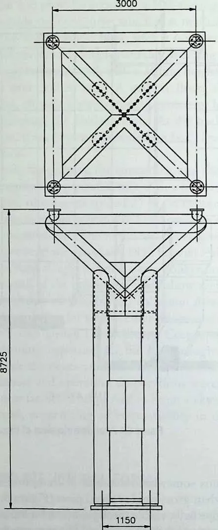
10 Derived from the 27-m spans used within the exhibition halls, the basic structural unit of the exhibition center is a 27-m bay covered with a space frame roof supported at each 8.725-m-high column at four comers of an inverted pyramidal column capital on 400-mm-diameter circular base plates 3 m apart. At each of these points, the space frame is either fixed, free, or permitted to slide in either the N-S or E-W directions, depending on the location of expansion joints in the roof and the requirement for restraint to support lateral loads. Below the inverted pyramidal top are four 400-mm shafts centered on the four comers of a 1.5-m square that are welded to a base plate bolted to the concrete floor of the upper exhibition level. The sculptured
12 38th STREET
13 Figure 6.1 Axonometric view of the Javits Center.
14 th STREET
15 shape of these columns somewhat resembles delicate, multistemmed champagne glasses rather than gross single-legged piers (Figure 6.2).
16 The 27-m repetitive bays, visible throughout the building, unify the structural rhythm of the entire exhibition center: The concourse and galleria are the width of one bay, whereas the exhibition halls are formed by the repetition of many such bays. Through the variety of heights defined by the space frames and the sculptural quality of the frames themselves, the design achieves a reduction of scale in the formation of the building itself.
17 Along the building’s exterior, the form of the space frames and columns is mirrored in the building’s facade. The skin of the building is modulated by the metal of the frames and a range of reflective glasses. Transparent glass forms the lower facade of the entrance hall and the concourse, as well as that of the galleria and restaurants; the remaining facades are translucent or opaque glass. The skin articulates the functions of the building and expresses the form of the structural unit. The result is a single, unified rhythm, integral to the structure, patterned to reduce scale (Figure 6.3).
18 The interior illumination of the building differs significantly from most
2122Figure 6.2 Column elevation.
23 glass architecture in realizing the possibility of using natural light as a means of visually defining interior spaces. The public spaces are articulated, not by walls, but by a soft, evanescent fight filtering in from outside the building through the tinted glass that reduces the light entering the building and permits views outside the building.
24 The center’s design presents a rare opportunity, in the tradition of the great exposition palaces of the 19th century, to demonstrate the innovative use of modem technology. It is perhaps closest in concept to the Crystal Palace built for the 1851 London Exhibition, although images are also present of the Galerie des Machines built for the 1889 Paris Exhibition.
26 Figure 6.3 Juxtaposition of column and space frame.
27 The Crystal Palace, a 72,000-m2 structure, 555 m long (which is 1,851 feet long, matching the year of its construction), was a prefabricated iron structure based on a 1.2-m module corresponding to the maximum glass size that was produced at the time. Those who saw it before its destruction by fire in 1937 spoke of its romantic beauty and said, ‘‘it is a Midsummer Night’s Dream seen in the clear light of midday.’’ It is this same image that the Javits Center tries to evoke. Clearly, it is the structure of the building, more than any other element, that contributes to the crystalline quality of the design.
28 What is interesting is the process leading to the solution. From the beginning, an organic approach was sought that would tie together the various forms. The space frame, which covers the horizontal planes, turns comers, climbs in steps to the top of the great hall, and descends to the ground, does so without violating the ‘‘pure tetrahedral geometry’’ of its smallest unit. Specified as an assembly of steel pipes and spherical steel nodes, the space frame geometry is the master to which the designer is the servant. The deft and elegant maimer in which the elements are handled demonstrates how imaginatively prefabricated elements can be handled by a competent designer.
29 Based on a 3 X3-m horizontal module, 1.5 m deep, the space frame is stiffened along the column lines by diamond trusses formed by a second layer of the standard tetrahedral geometry. The whole assembly behaves much like a flat plate with reinforced column strips. At the columns, a third layer of space frame creates a drop panel completing the analogy. The column itself contains the capital, an inverted pyramid, sitting on four stiffened shafts of steel-clad reinforced concrete (for fireproofing) (Figure 6.2). The column capital member sizes use 400-mm tubes, 40 mm thick for diagonals and 13 mm thick for horizontals. Material for these tubes is ASTM A618 Gr 2 (F7 = 345 MPa). The crossed base of the inverted pyramid consists of butt-welded 38-mm-thick gusset plates of ASTM A3 6 steel (F? = 248 MPa). These are, in turn, welded to bearing plates at the top of the four vertical 400-mm-diameter concrete-filled steel shafts.
6.3
31JOINTING
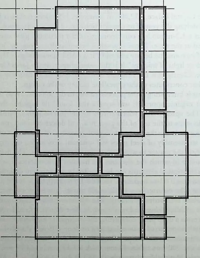
32 Because of its size, it was necessary to divide the roof area into eight units, each of which would respond independently to movements and deformation resulting from temperature variations (Figure 6.4). Two conditions were considered:
- 1.
- Maximum temperature variations during construction: 3 5 °C with large permissible deformations and stresses.
- 2.
- Maximum ambient temperature variation during operation, after the building is closed in: 15°C with small deformations and stresses.
3637Figure 6.4 Layout of roof regions.
38 PLAN
41 Figure 6.5 Unidirectional sliding bearing.
42 Figure 6.6 Expansion joint
44 EXHIBITION HALL
45 CENTRAL HALL
46 Figure 6.7 Wall/roof expansion joint.
48 Consistent with these principles, three types of supports were designed for the space frame at the top of the columns: fixed, free, and one-way sliding (in one of the two orthogonal directions). In general, the center of a unit between expansion joints was fixed and the unit was permitted to expand outward from this center. As a result, no more than two bays, or 54 m, of the continuous space frame is fixed against expansion and the resulting bar forces are no more than 10 percent of the total design forces.
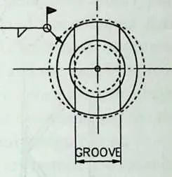
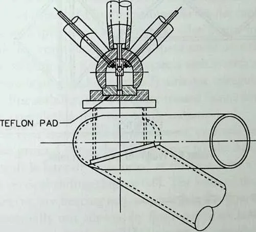
49 Most of the roof units are required to resist lateral wind forces, because they are either continuous with exterior walls or support mullions from entrances or curtain walls. These wind forces are resisted at fixed supports as well as sliding supports that are perpendicular to the wind direction (Figure 6.5).
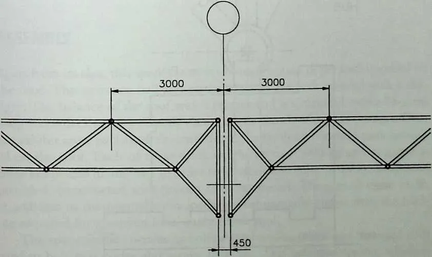
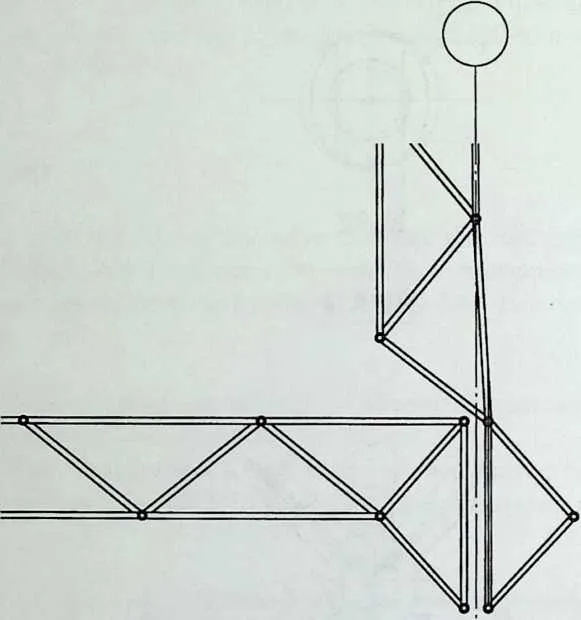
50 In plan, the repetitive grid of column locations is carried out without regard to the location of expansion joints. As a result, the pure geometry of the space frame is distorted at these locations to accommodate the expansion joints. Two such conditions exist in the building. In the flat roof area, the diamond-shaped beam is split into two triangular edge beams spaced 450 mm apart, each of which is continuous with the space frame on either side of the joint (Figure 6.6). Where the flat roof intersects with a vertical wall, a more complicated division is provided (Figure 6.7) with one triangular beam hanging from the wall. For stability, the triangular trussed beams have diagonals in the vertical plane, completing the truss configuration.
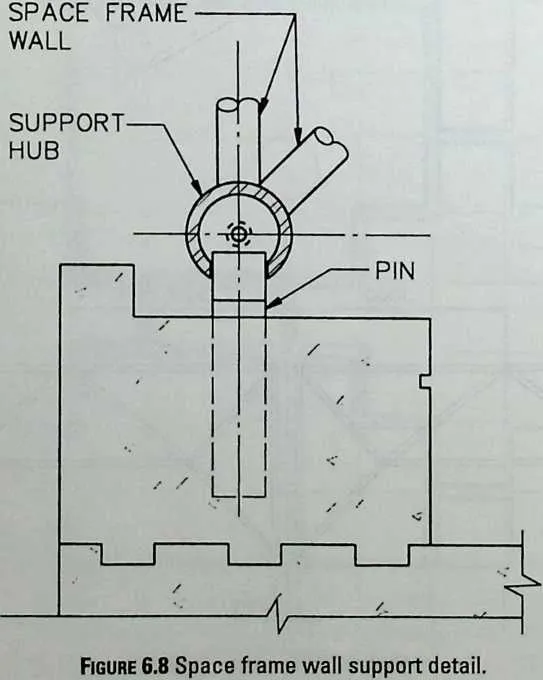
51 In general, the roof is supported on the columns, even where the wall continues down to the ground along the 11th Avenue facade. At these locations, the space frame wall is laterally supported at the base with a detail connection that permits vertical sliding (Figure 6.8). The walls of the three bays on 12 th Avenue, however, are bearing and supported on the floor slab. This condition, which is normally not allowed by fire regulations, was permitted on the condition that an automatic sprinkler system be provided covering the full area of the walls.
52 ASSEMBLY
53 Apart from its size, this space frame is unusual because of the loads imposed on the roof. The entrance hall and restaurant area are both covered with a skylight. The balance of the roof area is opaque and is structured with a 75-mm-deep metal deck resting directly on the upper chords of the space frame. Over the exhibit area, packaged air-conditioning units sit on concrete pads provided on the roof. Each of these units weighs up to 10,000 kg and as many as three are placed in one bay. In order to service these units, pathways have been provided, constructed with precast-concrete pavers. The sum of these loads, in addition to the normal snow loads, are substantially higher than the loading required for a conventional space frame roof.
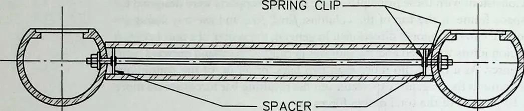
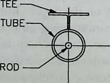
54 The space frame consists of hollow steel nodes, tubes, and threaded rods used to bolt two nodes and a tube together. This patented system, which is known as the PG System, operates as follows: The tubes carry all compressive


56 WASHER
57 Figure 6.9 Typical member-hub connection detail.
58 PLAN
59 SECTION
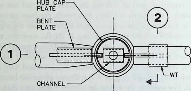
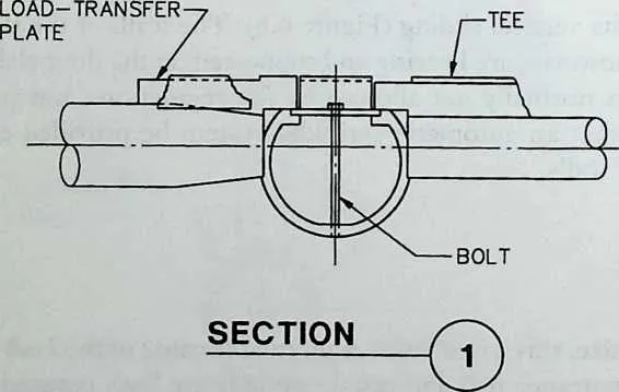
6162Figure 6.10 Top chord roof deck support.
63forces, and rods, all tensile forces. The rods, which run from node to node, provide a level of prestress to the system, which varies depending on the rod size (Figure 6.9). The diameter of the rods varies from 13 to 83 mm and they are made of high-strength steel with an ultimate strength of 1,035 MPa and a yield strength of 863 MPa. A total of 75,000 rods are used in the project.
64Tubes, which vary in diameter from 75 to 215 mm, are 365-MPa-yield- strength material. The actual tube strength varies by ± 13 percent, depending on the tube diameter. Larger tubes are swaged (tapered down at the ends) to avoid interference with adjacent tubes at nodes. Where tubes are required to support transverse loads, such as at the top chord of the roof, they are reinforced with a tee or channel. This reinforcing extends onto the node to provide a positive load transfer device (Figure 6.10). For light lateral loads, a bearing washer between the tube and the rod placed within 20 mm of the end of the tube provides the load transfer mechanism. Tubes are cut square at the ends and therefore bear on the spherical node along a line. Local yielding is assumed to take place along this line bearing due to the Hertz contact pressure.
65Hollow nodes used on this project have an outside diameter of 215 and 240 mm and vary in thickness from 19 to 38 mm. These nodes, with a strength of 863 MP a/1,03 5 MPa (yield/ultimate), were originally conceived as cast steel. In order to provide the required 19,000 nodes in time, it was necessary to seek more than one supplier. A Japanese manufacturer (who eventually supplied one-third of the total required) was found who was able to forge the nodes rather than casting them.
66 ANALYSIS
6869The analysis of the structure was performed using the NASTRAN program, modeling the space frame as a truss system. Each region defined by expansion joints or free edges was analyzed separately.
70The largest region, with over 20,000 bars and 5,100 nodes, is the central hall area. It is also the most complex with both vertical and horizontal surfaces as well as columns made up of space frame elements. The second-largest region, a portion of the exhibit hall roof, has almost 15,000 bars, and the smallest region is a single bay with 1,500 bars (on average, there are four bars per node). Each region was analyzed for five loads, dead loads, wind and temperature effects as well as snow loads in a checkerboard pattern. Various combinations of these loads were considered and the most critical combination was determined for each member in the roof. An iterative approach was used to size members with corrections introduced in each subsequent run. A maximum of three iterations was used to produce a final list of members.
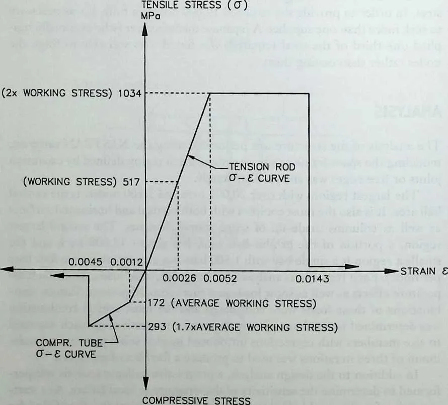
71In addition to the design analysis, a progressive collapse analysis was performed to determine the sensitivity of the structure to local failure. As a starting point for this analysis, it was assumed that a critical member failed for whatever reason. For this purpose a critical member was defined as the bottom chord of the diamond beam at the center of the span, or a diagonal just above the support column. Nonlinear member properties were defined for the bars: Tension bars were modeled as elastoplastic members; compression bars were modeled as nonlinear elastic bars approximating the buckling behavior obtained from actual tests of a range of tube diameters (Figure 6.11). An additional criterion was imposed stating that if a node became unstable due to failure of all but two bars connected to the node, the load applied at that point was removed. From a physical viewpoint, this implies that the load falls to the ground if the node fails. A stepwise solution of the problem using the MARC program was performed with four load increments. In order to obtain preliminary indications of the extent of a potential collapse, static runs were performed with critical bars removed at various locations. The inherent strength of the continuous indeterminate space frame is apparent from these preliminary analyses. Removing members anywhere within the fabric of the structure was shown to be not critical and redistribution of forces easily accommodated the loss of the member. Only on the perimeter bays was any significant collapse shown to occur due to removal of a critical member. Even here, the extent of the potential collapse was shown to be limited to the affected bay.
7475MPa
76Figure 6.11 Stress-strain diagram for tension rod and compression tube.
77 FABRICATION AND CONSTRUCTION
7980For ease of fabrication, the roof was assumed to be built without any camber. As a result, the natural deflection of the roof under load results in a low point at the center of a bay. For redundancy against possible ponding, two drains were provided in the vicinity of this point. In addition, a minimum deflection was specified to assume adequate slope for drainage of the roof. The bays covered by skylights, on the other hand, drain to channels that were incorporated into the skylight construction along a square 3 m from the edge of the roof. In this case, the skylight channel is posted up from the space frame and sloped to these drains. This imposed a stiffness requirement on the space frame as maximum deflections were specified.
81On the facade and at entrances, the design of the space frame is controlled by stiffness rather than strength requirements. The limitation on the deformation of glass panels and entrance doors, both of which are attached to the space frame, limits the permissible deflection of the space frame. This requirement resulted in oversizing members and, in the case of the concourse facade, in adding a stiffened edge to the space frame wall. Two criteria were the determinants for this condition: First, the racking of a 3-m square facade panel is limited to 6 mm and, second, the out-of-plane twist is limited to 6 mm.
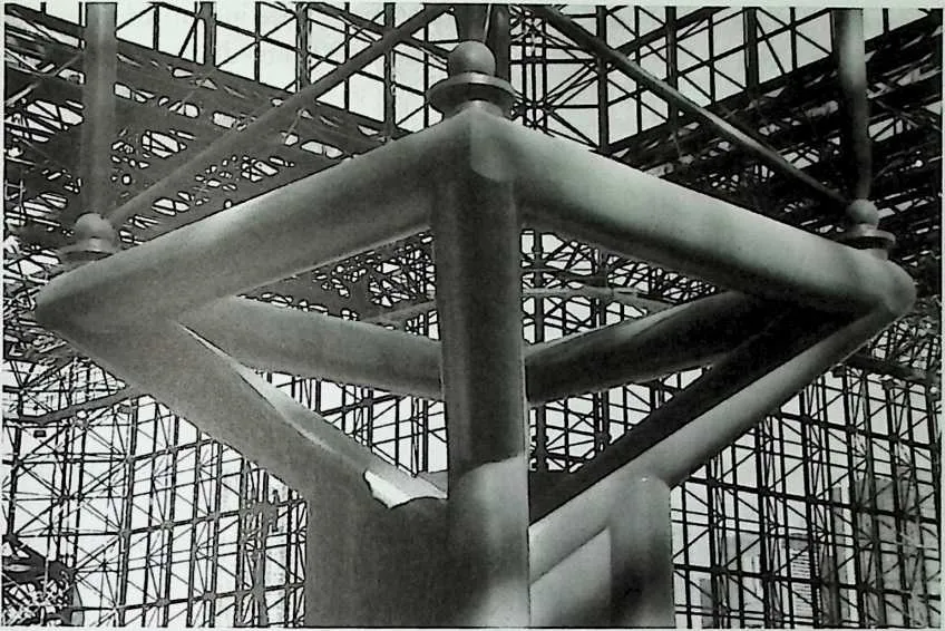
82The sculptural columns supporting the space frame were required to conform to a building code ordinance that the columns be fireproofed to a point 7.5 m above the floor. This requirement was met by filling the four steel shafts with reinforced concrete. Under symmetrical loads, the pyramidal capital acts essentially like a truss with tension in the horizontal tie members and compression in the diagonals. Under nonsymmetrical loads, significant bending is introduced in the diagonals, which tend to act as cantilevered branches from the vertical trunk of the column. The details at the four comers of the capital were developed without external gussets to provide an elegant solution. The 400-mm-diameter space frame base plate is supported by a 250-mm vertical pipe, which is, in turn, welded to an inclined 38-mm-thick plate welded to the diagonal arms of the capital. The horizontal tubes are then welded to each other and the 250-mm vertical pipe at the mitered comer. After welding, a reinforced epoxy filler was used at the mitered comer to form a clean curved fine after welding, a solution that proved to be more economical than filling with weld metal and grinding (Figure 6.3). The comers themselves were originally conceived as three-dimensional cast-steel elements, but because the same visual and structural result could be obtained by a weldment at substantially lower cost, the welded solution described here was chosen.
83The four 400-mm-diameter columns below the capital are filled with 40- MPa concrete as are the midlength cross braces. This concrete was pumped in from the bottom prior to the attachment of the capital. At the base of the columns, both the shell and the reinforcing bars are welded to the base plate, achieving the required tensile resistance against overturning moments.
84Stringent vertical and horizontal tolerances had to be maintained in the assembly and fabrication of the capital. The four bearing points have a center-to-center tolerance of 2 mm in 3 m and were required to be in plane within 3 mm. In order to meet these tolerances, a sequence of welding and assembly was developed to minimize thermal distortion due to welding and a jig was used for both the subassemblies and the final assembly. Welding procedures required both preheat for all heavy plates and tubes and the use of E70XX electrodes. In the final assembly, a boxed cover enclosed the crossed plates below the capital to match the dimensions of the cross-stiffeners of the vertical shafts of the column. Apart from this concession to visual architectural requirements, the structure of the column assembly is totally exposed, protected by a thin film of epoxy paint.
85 CONSTRUCTION
86 Stringent tolerances were maintained throughout the fabrication and erection of this structure. These tolerances started with the column location, which was controlled to within 8 mm in the two orthogonal directions. For the space frame itself, individual tubes are within 1 mm of specified length and the overall assembly is within 8 mm per 27-m bay. These strict tolerances were required to ensure proper fit of the elements without forcing and inducing built-in stresses into the assembly. In order to obtain these tolerances, extraordinary controls were established for the fabrication and assembly process. Jigs were used to check each tube length and subassemblies were prepared in highly accurate frames.
87 The erection process was devised taking into account the required final tolerances. The flat roof of the exhibit hall was divided into subassemblies, each of which was transportable. A typical bay consisted of four beam elements, two of which sat on the columns, and a central 18-m square divided into three 6X18-m strips. These three strips were joined together by stitching on the ground prior to lifting (Figure 6.12).
88 Erection started with the four beam elements. When these were stitched together to form a ring, the center section was lifted in one piece and temporarily suspended from four corners at an elevation slightly below that of the adjacent beams while the stitching process took place. Stitching members were first loosely installed. Torquing of nuts at the end of the rods pulled the central section into alignment with the previously placed beams.
89 Erection of the cubes over the central hall presented a further complication. Each cube, except the one at the center, is supported by four walls, one of which belongs to the cube at the next-higher level. This required a sequence whereby the supporting walls had to be erected first before placing the central sections, which, in turn, entailed temporary cable bracing particularly for the four space frame columns in the central hall.
90 The schedule for erection required completion of a minimum of two bays per week. As there are a total of 71 bays, a total erection time of nine months was anticipated and met!
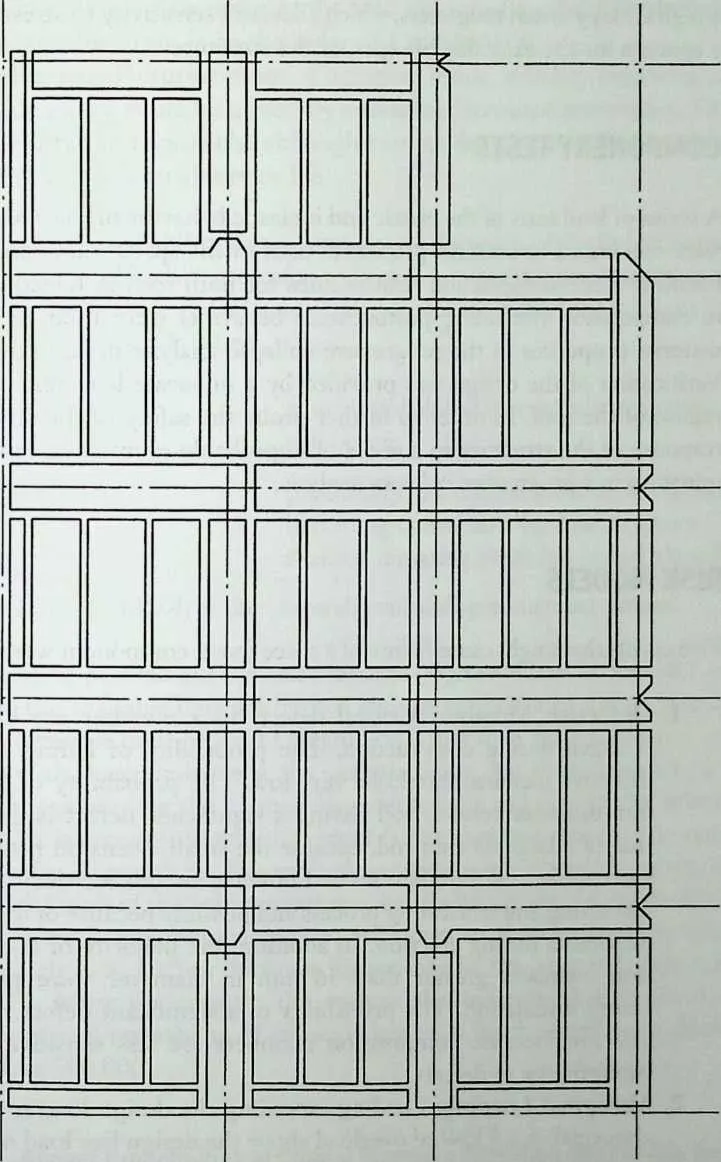
92 Figure 6.12 Layout of subassembly units.
93 Stringent controls were established for every step of the fabrication and erection process. The cast-steel nodes were subject to visual, magnetic particle, and radiographic inspection. Flaws in the castings such as cracks or voids, which were not repairable by welding, were cause for rejection. Particular attention was focused around the open mouth of the casting where high stresses were shown to exist by analysis. The high-strength rods with upset rolled threads were inspected for defects. Rolled threads were called for, instead of cut threads, to avoid notch sensitivity. The material for the rods has
9596a high Charpy notch toughness, which alleviates sensitivity to stress corrosion, a concern for the extended life span of the structure.
97COMPONENT TESTS
98A series of load tests of the elastic and inelastic behavior of the rods and tubes were conducted to confirm properties used in the space frame analysis. The resulting force-deformation relationships for both rods in tension and tubes in compression (including postbuckling behavior) were used to define the material properties in the progressive collapse analysis described previously. Verification of the design was provided by a full-scale load test of a 14-bay region of the roof. In order to further probe the safety of the structure, the response of the structure to a series of improbable events was explored, culminating in a progressive collapse analysis.
99RISK MODELS
100Five events that might cause failure of a space frame component were identified:
- 1.
- Defective Member: Critical defects in a member are likely to be detected during construction. The probability of failing to detect a defective member should be very low. The probability of a small 13- mm-diameter tension rod having a significant defect is greater than that of a large 83-mm rod, because the smaller tension rods are more susceptible to discontinuities and notches introduced during the manufacturing and fabricating process and possibly because of less stringent inspection during erection. In addition, the majority of the large tension members greater than 36 mm in diameter were proof-tested before installation. The probability of a significant defect in a tube is also low, because compression members are less sensitive to loss of strength due to defects.
- 2.
- Abnormal Loading: Loading exceeding the design load is considered abnormal. A 1.9 kN/m2 overload above the design five load over at least one bay, owing to an accumulation of slushy snow, for example, would be a very rare occurrence. Even application of the full design five load of 1.9 kN/m2 , with no overload, over at least one bay would be an uncommon occurrence, happening perhaps only a few times during the lifetime of the roof.
- 3.
- Human-Induced Accident: The probability of failure as a result of an event such as a crane hitting a critical member or uncontrolled welding on a sensitive, highly stressed member is very low. Fire was not included in this analysis.
- 4.
- Catastrophic Event: Events such as an airplane or a large wind-driven missile crashing into the structure are also extremely rare. Even with the high level of air traffic in the area, the annual probability of such a catastrophic event is on the order of 1 in 1,000,000.
1031045. Unknown Deterioration: Corrosion inside tubular members, or inside joints, could be missed by normal maintenance procedures. This deterioration is possible, although very unlikely, in an inside environment over a normal service life.
105 Approximate probability values were assigned to each of the five initiating events for three different types of members (13-mm-diameter tension rods, 76-mm-diameter tubes, and 83-mm-diameter tension rods). These values are summarized in Table 6.1, where
106 P(A) is the annual probability that an initiating event
108109will occur;
110 P(M/A) is the probability of a critical member failing and
112113becoming unavailable for loading given that the initiating event has occurred; and
114 P(M)=P(A) X P(M/A) is the overall probability of member failure.
115 It should be pointed out that the estimates of probabilities in Table 6.1 are subjective; the available data are limited and the probabilities should be considered in terms of their orders of magnitude rather than exact numerical values. Even with these limitations, the analysis shows that the risk of failure is several times greater for the 13-mm-diameter tension rod than for the tube or larger rod. It is recognized that the risk of failure during a catastrophic event is the same for all members. However, the analysis suggests that the probability of failure for all of the other events may be 10 times higher in the small 13-mm tension rods (approximately 2 X 10⁻⁶) than in the compression tubes (approximately 2 X 10'7) or 50 times higher than in the large rods (approximately 10*). More importantly, the analysis also indicates that, in absolute terms, the annual probability of failure is low even for the small rods: on the order of 1 in 500,000.
116 TABLE 6.1 Annual Probabilities of Critical Members Becoming Unavailable for Loading Given the Occurrence of an Initiating Event and Probabilities of Initiating Events
|
1202=Initiating Event |
13-mm
Tension
Rod
|
76-mm-Diameter
Tube
|
83-mm Tension Rod
| ||||||
|
122P(M/A) |
123P(A) |
124m |
125P(M/A) |
126P(A) |
129P(M/A) |
130P(A) |
131P(M) |
||
|
1321. Defective member |
13310* |
13410* |
13510* |
13610* |
13710* |
13810* |
13910* |
14010* |
14110* |
|
1422. Abnormal loading |
14310* |
144106 |
14510* |
14610’’ |
14710* |
14810* |
14910* |
15010* |
15110* |
|
1523. Human-induced accident |
1531 |
15410* |
15510* |
156102 |
15710* |
15810* |
15910* |
16010* |
16110* |
|
1624. Catastrophic event |
1631 |
16410* |
16510* |
1661 |
16710* |
16810* |
1691 |
17010* |
17110* |
|
1725. Unknown deterioration |
17310’’ |
17410* |
17510* |
17610’’ |
17710* |
17810* |
17910* |
18010* |
18110* |
|
182Summation YP(M/A) P(A) |
183= |
1843x10* |
187=10* |
190=10* |
|||||
199200ULTIMATE LOAD CAPACITY
201Based on the results of the risk analysis, four cases were explored to determine the ultimate capacity of the roof structure. The region of the roof that was analyzed consisted of the 14 bays on the north end, with a uniform live load of 1.9 kN/m2, in addition to the dead load applied over the entire roof. The corner bay (Figure 6.13) was then loaded until a large number of members had failed as defined by fracture of tension members and postbuckling of compression members. The four cases that were studied and the results are as follows:
202 Ultimate Load Capacity
as a Multiple of Design
204205Case Condition Live Load (1.9 kN/m2)
- 1.
- Roof as built 3
- 2.
- Smallest tension member: 3
20820913-mm rod removed from
210bottom chord of diamond truss
- 3.
- Small compression member: 3
21321476-mm tube removed from
215bottom chord of diamond truss
- 4.
- Largest tension member: 0.75
21821983-mm rod removed from
220bottom chord of diamond truss
221The analysis on which these results are based considered nonlinear member properties and assumed a 3 percent sliding friction coefficient at the Teflon support bearings. Intermediate cases were also studied with results similar to those shown previously.
222COLLAPSE ANALYSIS
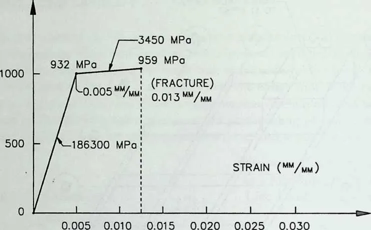
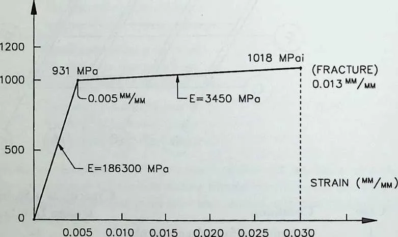
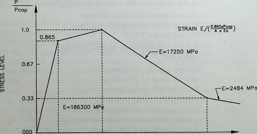
223A nonlinear model of the structure includes separate force-deformation relationships for tubes and rods. For tubes, the postbuckling behavior is modeled based on earlier tests. For tension rods, yielding and fracture are similarly based on tests with the tensile area at the thread used to define member strength. Because of different steel quality, the ductility of rods below 18 mm in diameter was less than that of large bars (Figures 6.14 to 6.16).
224Using a nonlinear version of the SAP IV program run on a CDC 7600 mainframe, loads were applied incrementally to the roof, making multiple runs to obtain convergence of the solution. Initial load increments were large (0.9 kN/m2) and were decreased to 0.2 kN/m2 as the capacity of the structure was approached. Loading was continued until a load level was reached for which no stable solution was achieved. The following table summarizes the results obtained for the five cases studied:
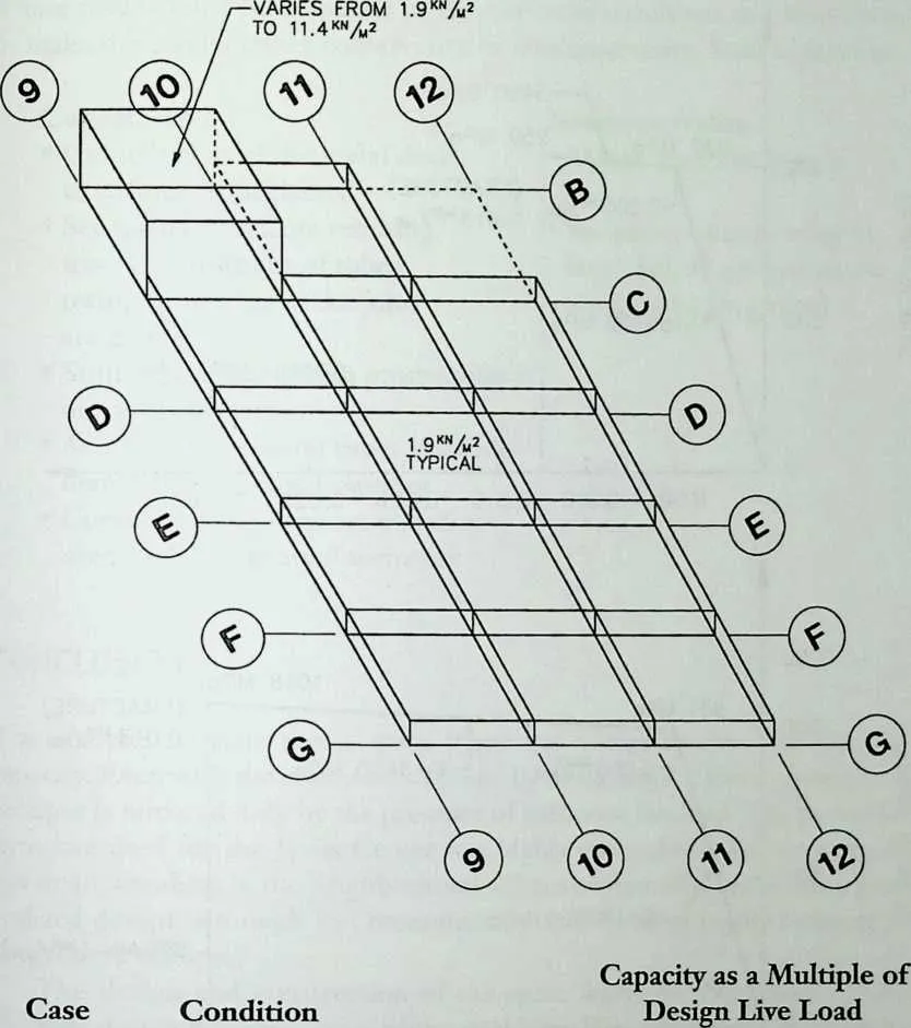
226 Figure 6.13 Loading condition for ultimate load capacity.
- 1.
- As built—uniform dead load plus 3+
2292300.9 kN/m2 over entire roof. Loaded
231in the southwest corner incrementally.
- 2.
- 13-mm tension rod removed from 3+
234235bottom chord of diamond truss. Same loading as case 1.
- 3.
- As built—incrementally applied load over 3.5+
238239entire roof.
- 4.
- 8 3-mm tension rod removed from 0.25+
242243bottom chord of diamond truss.
244Incrementally applied load over entire roof.
- 5.
- Catastrophic event: diamond truss and 0.10+ portion of adjacent space frame removed. Incrementally applied load over
247248remaining roof.
249 cn tn Ld or
250 tn
251 Figure 6.14 Force-deformation relationship for 13-and 16-mm tension rods.


254 tn tn Ld (Z i—
255 tn
256 Figure 6.15 Force-deformation relationship for 18-mm and largertension rods.
257 Figure 6.16 Force-deformation relationship for typical compression tube.
258 1.0
259 3.0
260 8.4
262 These results must be evaluated in the context of conditions that would tend to make the results either conservative or nonconservative. Such factors are:
263 Conservative
264 Nonconservative
- Dynamic effects ignored
- Secondary effects owing to large deflections (geometric nonlinearity) neglected
- Contribution of the metal deck to stiffness is neglected
- Secondary moments resulting from end restraint of tubes owing to friction at the joint are neglected
- Stiffness resulting from prestressing of rods is neglected
- Actual test results on tubes and rods higher than assumed capacity
- Conservative interaction equation used to define flexural members
6.4 CONCLUSION
266The analyses indicate that a space frame has a large reserve load-carrying capacity. Even with the condition imposed by a catastrophic event, progressive collapse is initiated only by the presence of sufficient live load. The particular structure used for the Javits Center was highly optimalized, and, as a result, has small members in the neighborhood of lines of contraflexure. A more generalized design, although less economical, would be more highly resistant to progressive collapse.
267 The design and construction of the space frame for New York’s Javits Center presented unique and complex problems. The solutions to these problems demonstrate the adaptability of the space frame concept to specialized applications. Starting with a defined geometric configuration, modifications to a standard-component prefabricated system are shown to be readily made. The flexibility of the system extends to the originality of the construction solution. Although few structures of such a large scope may be built, lightweight, steel, space frame construction should find application to more modest enclosure problems and should be an integral part of the design repertoire of architects and engineers.
6.5 BIBLIOGRAPHY
269Levy, M.: ‘‘New York Convention Center Space Frame,’’ IASS Symposium, Dortmund, 1984.
270 Levy, M., and C. Chow: ‘‘Load Test Verification of Space Frame Roof Design, Space Structure,’’ International Journal of Space Structures, Vol. 3, No. 1, 1988.
271 Wiss, Janney, and Elstner: ‘‘Results of Analysis II for J.K. Javits Convention Center Space Frame.’’