
13 Tensegrity: Theory and Application
2Ariel Hanaor
13.1 INTRODUCTION
3Characterization
4 The terms tensegrity and tensegrity structures are not well defined, and have been used to designate widely differing types of structures in different contexts. The vagueness of the term, which was coined by R. Buckminster Fuller, stems from Fuller’s lack of clear definition in either the geometrical or the structural context:1–3
67The word tensegrity is an invention: it is a contraction of tensional integrity. Tensegrity describes a structural-relationship principle in which structural shape is guaranteed by the finitely closed, comprehensively continuous, tensional behaviors of the system and not by the discontinuous and exclusively local compressional member behaviors. Tensegrity provides the ability to yield increasingly without ultimately breaking or coming asunder.4
8 Fuller’s definition implies a network consisting of tension members (cables) and compression members (bars), in which the cable network is continuous (hence ‘‘tensional integrity’’), and the bar system presumably is not (‘‘exclusively local,’’ see the following figures). He endows the concept with mystical qual-
9 Beyond the Cube: The Architecture of Space Frames and Polybedra, edited by J. Francois Gabriel ISBN 0–471–12261–0 © 1997 John Wiley & Sons, Inc.
10 ities: ‘‘All structures, properly understood, from the solar system to the atom, are tensegrity structures. Universe is omnitensional integrity.’’ Such a sweeping generalization renders the definition useless. Fuller goes on to equate tensegrity and pneumatic structures (‘‘Tensegrity structures are pure pneumatic structures…’’), when, in fact, these are totally different structural systems. Following are some of the more precise definitions used in the literature.
11 The widest definition of tensegrity structures, from the geometric point of view, is sometimes used by mathematicians in the field of discrete geometry. They define tensegrity structure as a pin-jointed network consisting of any combination of bars, struts, and tendons. Bars are straight members of fixed length and can sustain either compression or tension. Struts are straight members with a lower bound on length. They cannot contract but they can extend indefinitely in a ‘‘telescoping’’ fashion and therefore cannot support tension. Tendons are straight ‘‘cables’’—members with an upper bound on length. They cannot extend but can contract freely and therefore cannot sustain compression.
12 This definition covers the whole range of pin-jointed structures, including trusses and cable networks. The narrowest definition of tensegrity structures, in the geometrical context, is: a network consisting of tendons and bars (or struts), such that any one bar is connected only to cables but to no other bar (except, perhaps, at the boundary). Thus the bar system, under this narrow definition, is completely disjointed. Such a system can be called ‘‘pure tensegrity.’’
13 A more general definition, in the structural context, is: an internally prestressed cable network. The ‘‘tensile integrity’’ aspect is covered by the well-defined term cable network, whereas the presence of bars is implied by the term intent ally prestressed, which indicates that the network does not require an external anchoring system, like conventional cable networks, but is prestressed internally by means of compression members (bars), which form part of the network. Emmerich5 calls them ‘‘self-tensioned structures,’’ but because any prestressed structure is ‘‘self-tensioned,’’ this is not appropriate. The concept of internal prestress is the key concept in tensegrity, because it is precisely this feature that distinguishes this type of structure from conventional cable networks and from pneumatic structures. This definition is generally adopted in the present work, but most of the discussion is limited to the more restricted class of ‘‘pure’’ tensegrity networks, in which bars are not mutually in contact.
14 One type of structure encountered in the literature under the ‘‘tensegrity’’ caption is a certain class of dome (e.g., the Georgia Dome in Atlanta), consisting of cables prestressed against a disjointed system of bars, but requiring a compression ring in the perimeter. This type of dome is clearly excluded from the preceding definition of tensegrity networks, because it is externally prestressed, incorporating an external anchorage system (the compression ring). Cable dome would be a more appropriate term for this type of structure.
15 Background
16 Few, if any, engineered structures of substantial scale exist that can fit the preceding definition of tensegrity structures. The London Zoo aviary (Figure 13.1) contains elements of tensegrity in the form of disjointed tetrahedra used
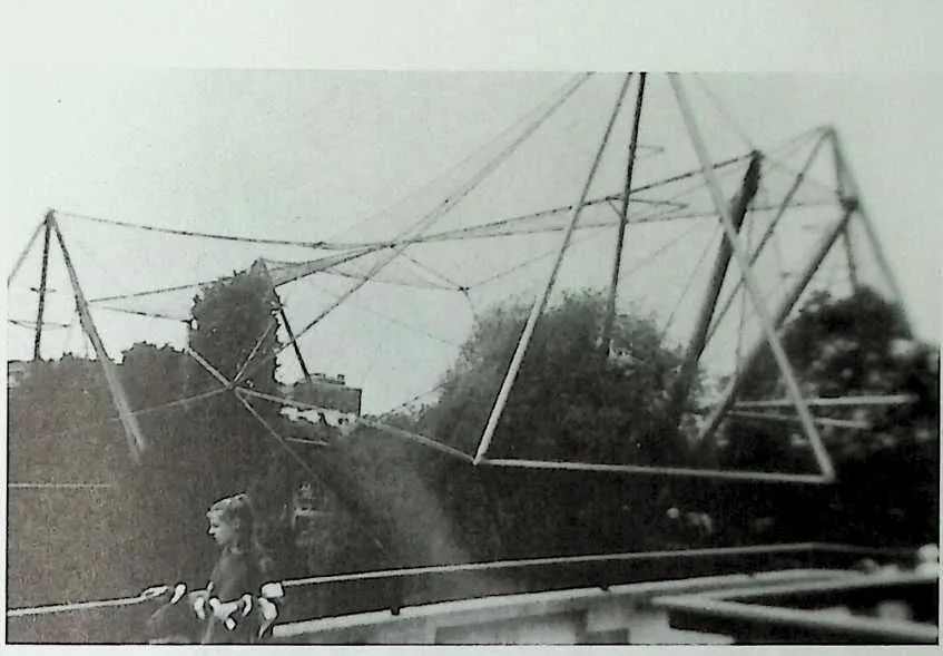
18 Figure 13.1 The London Zoo aviary.
2021in prestressing the cable network, but it also involves external anchoring (to the ground). A number of tensegrity sculptures exist, most notably by the artist Kenneth Snelson (Figure 13.2). These are ornamental objects of quite striking appearance located in various public places, mostly in the United States (Figures 13.3 and 13.4). The simplest object that can be perceived as a tensegrity structure, under the definition in force, is the kite. It probably served as the inspiration and starting point for more complex objects such as Snelson’s ‘‘sculptures.’’
22The first to conceive of tensegrity as a building structure was probably Fuller, arguably as a result of his collaboration with Snelson. His first patent for ‘‘Tensile-Integrity Structures’’ was filed in 1959.6 It is a dome of spherical surface consisting of struts and tendons such that struts are connected only to tendons at their ends and at the midpoints (Figure 13.5a and £)• In the patent application Fuller claims that the invention ‘‘has special application to structures of vast proportions such as free-span domes capable of roofing a stadium or housing an entire village or city,.. .’’7 This vastly exaggerated claim is based on the misconception that in very large domes the struts themselves can be constructed as tensegrity structures (Figure 13.5c), thus progressively reducing the relative length (or volume) of struts and generating an almost purely tensile structure, like a balloon. In the words of Fuller:
23Every time we can see a separate strut and can devise means for making a tensegrity strut of that overall size, we can substitute it for a previously ‘‘solid’’ strut. By such a process of progressive substitutions in diminishing order of sizes, leading eventually via sub-sub-sub-miniaturizing tensegri-ties to …a minimum ‘‘solid state’’ strut diameter, which corresponds exactly with two diameters of the atoms of which it is constructed…. The atom is a tensegrity, and there are no ‘‘solids’’ left in the entire structural system…. ’’8
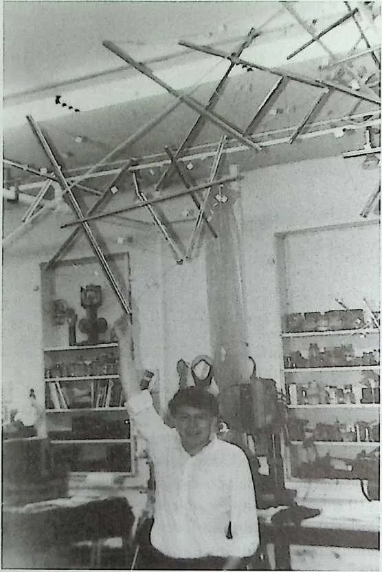
25 Figure 13.2 Kenneth Snelson in his studio in lower Manhattan (1990).
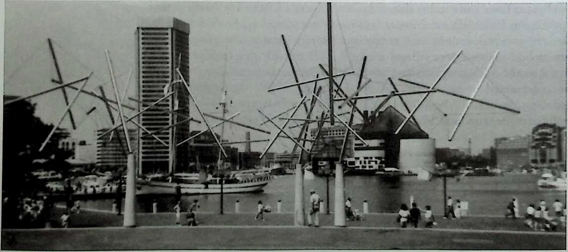
2829Figure 13.3 Snelson's sculpture in front of the Maryland Science Museum, Baltimore.
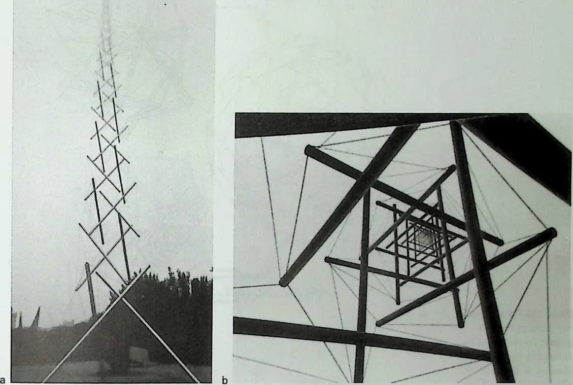
3233Figure 13.4 Snelson's ‘‘Needle Tower’’ at the Hirshhorn Museum of Modern Art, Washington, DC: (a) general view, (b) view from below.
34 Since the miracle of a purely tensile, freestanding structure has been achieved (‘‘no solids’’), there is practically no limit to achievable spans. The basic theoretical principle involved in this reasoning is that of material dilution. This principle, which applies to all structures, involves increasing structural depth without adding material (and therefore weight) in order to achieve larger spans. In tensegrity structures, as in all structures, the application of the principle is limited by practical constraints. The concept of tensegrity in general, and Fuller’s version of it in particular, suffers from other drawbacks, which will be discussed later.
35 Nevertheless, the credit goes to Fuller for opening the field of tensegrity structures for research and invention. Several other patents have followed over the years, including Fuller’s,9 but these appear to have produced no actual structures. The sections that follow review some of the main research topics and results. The research falls into two general areas. Most of the work is concerned with geometric configuration. Some limited research has been carried out into the actual load response of this type of structure, but a lot more is needed. The last section is a critical evaluation of the concept and its prospects for implementation.
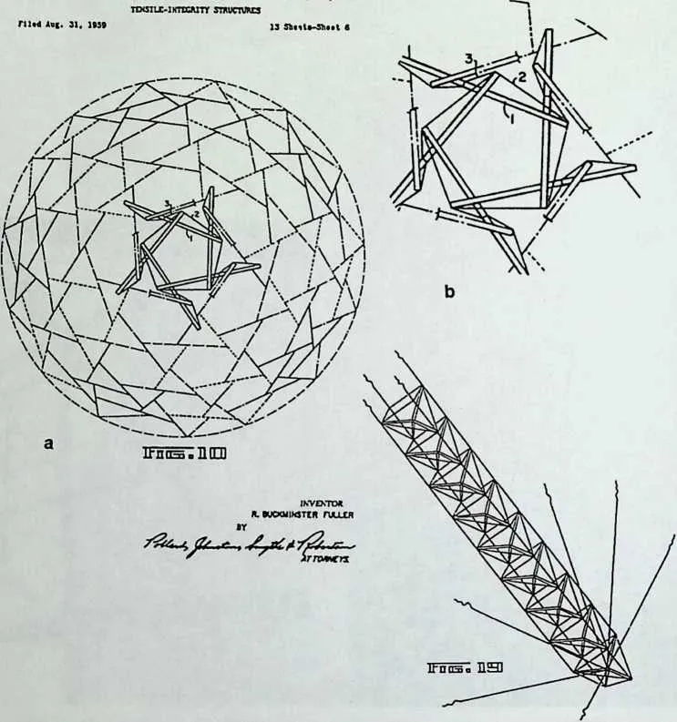
37 Figure 13.5 Fuller's tensegrity dome of his 1962 patent (a) plan, (b) detail, fc) tensegrity strut (Source: R. B. Fuller, ‘‘Tensile-Integrity Structures,’’ U.S. Patent 3,053,521, Nov. 13, 1962.)
38 Not. 13, 1962 r. b. fuller 3,063,521
39 GEOMETRY
40 Polyhedra
41 The simplest three-dimensional tensegrity object is the tensegrtty prism (T prism), the simplest of which is the triangular prism, sometimes termed simplex. A tensegrity prism is a skew prism formed by cables along the edges of the prisms, with bars along the diagonals of the side faces in a consistent sense. Figure 13.6 shows a number of these prisms. The two bases of the prism are rotated relative to each other by an angle that is dictated by the requirement for stability of the shape.10 For regular prisms (i.e., having regular base polygons), this angle is half the base polygon angle (30° for a triangular prism, 45° for a square prism, etc.). Right-handed and left-handed configurations can be distinguished, in accordance with the sense of rotation of the two bases. It is possible to add cables along diagonals of skew prism faces—the diagonals not occupied by bars—to obtain a reinforced prism. Figure 13.6e shows a triangular rein-
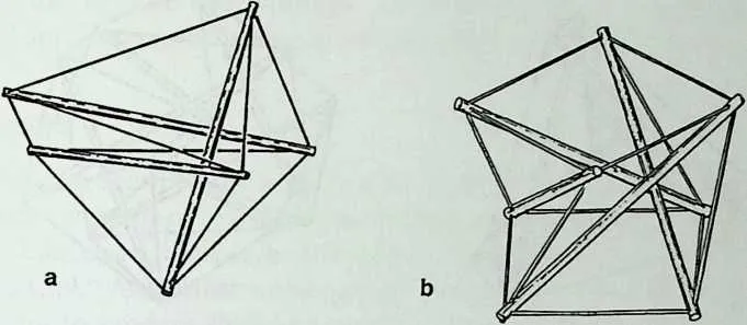
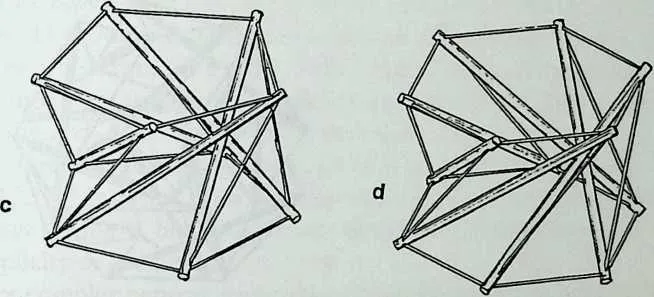
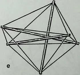
45 Figure 13.6Tensegrity prisms: (a) triangular, 6Wsquare, (c) pentagonal, (d)hexagonal, (e) triangular, reinforced.
46 forced prism, which has the property of geometric rigidity (see the following discussion under Load Response). The relative base rotation of reinforced prisms is no longer predetermined but can be varied in a range between the simple prism value, as a lower bound, and double that value, as an upper bound (at the upper bound the bars intersect at the centroid of the prism).
47 Higher polyhedra can be constructed. Figure 13.7 shows some relatively simple polyhedra, but any polyhedron can be constructed as a tensegrity.11,12 Emmerich shows a systematic way of deriving tensegrities from a range of Platonic and Archimedean polyhedra.13 Some of these polyhedra are shown in Figure 13.8. Fuller’s dome (Figure 13.5) is, in effect, a high-order tensegrity polyhedron obtained by geodesic subdivision of the sphere. It can be termed a geodesic tensegrity dome and is closely related to Fuller’s geodesic dome. It is
48 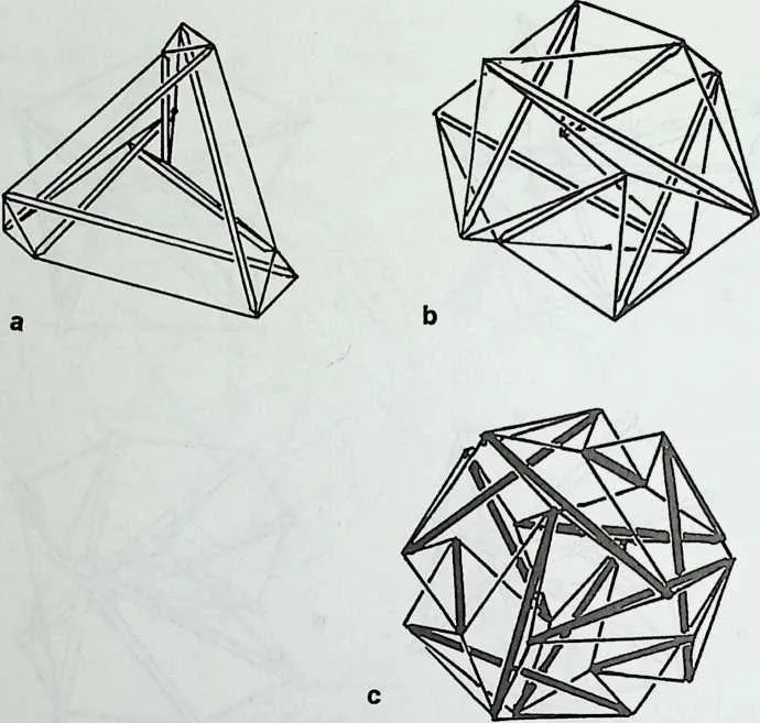
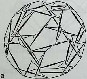
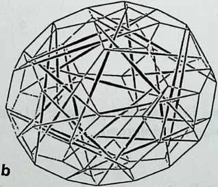
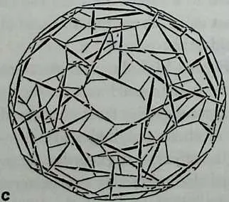
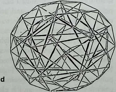 Figure 13.8 Some of Emmerich's Archimedean polyhedra:
/a/truncated dodecahedron, /"truncated icosahedron, (c) great rhombicosidodeca-hedron, (d)
small rhombi-cosidodecahedron. (Source: D. G. Emmerich, ‘‘Self-Tensioning Spherical Structures:
Single and Double Layer Spheroids,’’ International Journal of Space Structures (Special Issue on
Geodesic Forms), T. Tarnai, ed., Vol. 5, No. 3/4, 1990, pp. 353–374. Courtesy of Multi-Science
Publishing.)
Figure 13.8 Some of Emmerich's Archimedean polyhedra:
/a/truncated dodecahedron, /"truncated icosahedron, (c) great rhombicosidodeca-hedron, (d)
small rhombi-cosidodecahedron. (Source: D. G. Emmerich, ‘‘Self-Tensioning Spherical Structures:
Single and Double Layer Spheroids,’’ International Journal of Space Structures (Special Issue on
Geodesic Forms), T. Tarnai, ed., Vol. 5, No. 3/4, 1990, pp. 353–374. Courtesy of Multi-Science
Publishing.)
interesting to note that although the geodesic dome concept found widespread application, the
tensegrity concept has so far found none.
49 Figure 13.7 Tensegrity polyhedra: (a) truncated tetrahedron, (b) octahedron, (c) cuboctahedron.
50 Networks
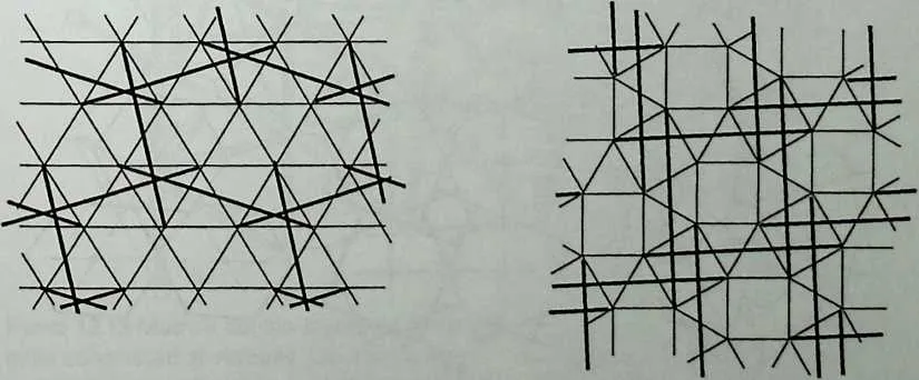
51 Whereas tensegrity polyhedra enclose a finite space, networks consist of repetitive patterns of bar-cable connections covering surfaces or filling space. Vilnay conceived single-layer infinite networks, a sample of which is shown in Figure 13.9.14 As a planar surface, these networks are not stable. They require curvature to produce shell-like surfaces. Double-layer networks can be produced by joining together tensegrity prisms. Some ways of joining such prisms to generate double-layer tensegrity grids (DLTGs) are shown in Figure 13.10.15 Figure 13.11 shows grids generated by these methods (only prism top and bottom bases are shown, for clarity). While the patterns are quite intricate, the lines joining the centroids of individual prisms form quite regular grids, termed the arch-grids. Figure 13.12 shows some simple models. A different way of joining T prisms to generate DLTGs is due to Motro and is shown in Figure 13.13.16 It differs from other networks in that it contains bar-bar connections at the joints, but it has certain advantages, such as continuity of cables and simplicity of geometry.
52 More complex network geometries can be generated by joining polyhedra of higher order. Emmerich produced some rather complex surface-covering and
53 Figure 13.9 Some of Vil-nay's single-layer tensegrity networks.
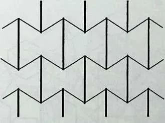
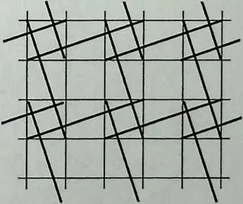
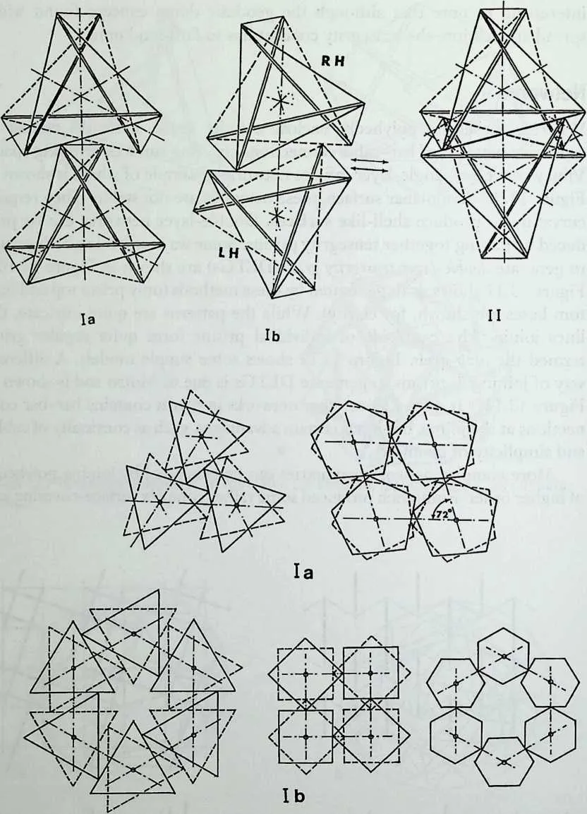
56 Figure 13.10 Methods of forming double-layer tensegrity networks from tensegrity prisms. (Source: A. Hanaor, ‘‘Double Layer Tensegrity Grids,’’ in Studies in Space Structures, H. Nooshin, ed., Multi-Science Publishing, Brentwood, 1991.)
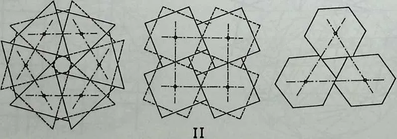
58 Figure 13.11 Double-layer tensegrity grids formed by the method of Figure 13.10. Top and bottom cable layers only are shown. Dash-dot line indicates arch-grid.
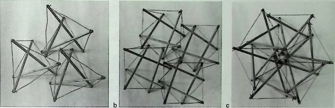
6162Figure 13.12 Models of double-layer tensegrity grids: (a) triangular type la, /d) square type II, (c) triangular type II.
63 space-filling configurations.17 Fuller and Grip developed a different type of space-filling network, a sample of which is shown in Figure 13.14.18,19
64 Structural Forms
65 Single-layer domes or domical surfaces can be formed on the basis of tensegrity polyhedra and geodesic spherical subdivision, such as Fuller’s dome (Figure 13.5). The use of polyhedra without face subdivision is limited to relatively small spans, as faces become impractically large with increasing spans. Single-
67 Figure 13.13 Metro's double-layer tensegrity grid using square prisms or truncated pyramids connected at vertices. (Source: R. Motro, ‘‘Tensegrity Systems and Geodesic Domes,’’ International Journal of Space Structures (Special Issue on Geodesic Forms), T. Tarnai, ed.. Vol. 5, No. 3/4,1990, pp. 341–351. Courtesy of Multi-Science Publishing.)
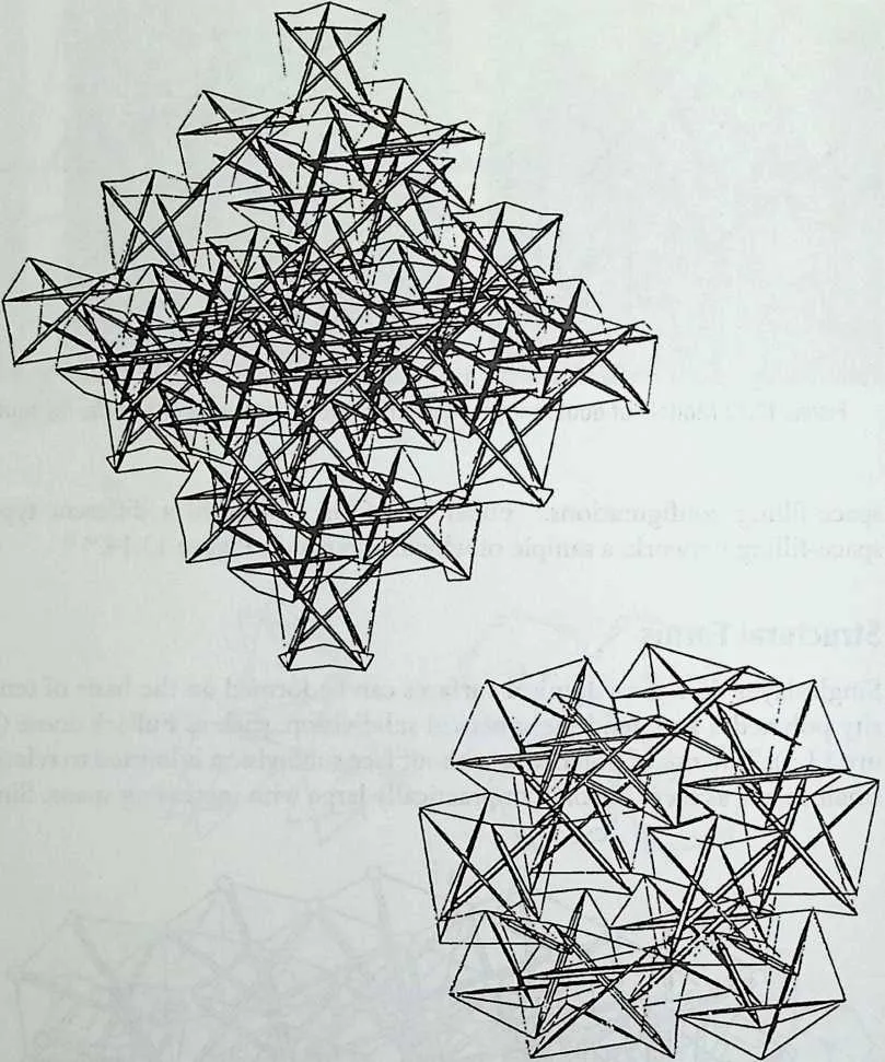
69 Figure 13.14 Some of Grip's multilayer and space-filling tensegrity grids. (Source: R. Grip, ‘‘The Correspondence Between Convex Polyhedra and Tensegrity Systems: A Classification System,’’ International Journal of Space Structures (Special Issue on Tensegrity Systems), R. Motro, ed., Vol. 7, No. 2,1992, pp. 3115–3125. Courtesy of Multi-Science
70 Publishing.)
71 layer curved surfaces of any shape can be generated from single-layer networks. Figure 13.15 shows a dome based on Vilnay’s network.20 This dome differs significantly from Fuller’s dome. In Fuller’s dome, as spans increase and curvature decreases, bars quickly come into contact with one another if module size is to be kept to a reasonable value. This is avoided in Vilnay’s concept but at the cost of increased bar lengths.
72 Emmerich developed double-layer domes based on hyper-polyhedra, in which the polyhedron face is replaced with a tensegrity truncated pyramid (T pyramid).21 This is, in fact, a T prism with base polygons of similar geometry but different sizes. Figure 13.16 shows one such hyper-polyhedron. The comment on the span limitation of domes based on polyhedra also applies to this concept, but the concept can be extended to include geodesic subdivision and to avoid both bar contact and excessive bar lengths. Bars are laced between two parallel cable surfaces and these surfaces can be kept wide enough apart to prevent bar contact.
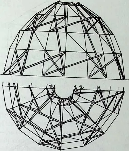
74 Figure 13.15 Vilnay's tensegrity dome based on single-layer tensegrity grid. (Source: 0. Vil-nay, Cable Nets and Tensegric Shells, Analysis and Design Applications, Ellis Norwood, New York, 1990.)
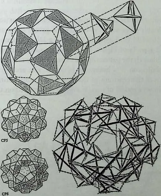
76 Figure 13.16 Emmerich's double-layer hyper-polyhedron and its derivation (from truncated icosahedron). (Source: D. G. Emmerich, ‘‘Self-Tensioning Spherical Structures: Single and Double Layer Spheroids,’’ International Journal of Space Structures (Special Issue on Geodesic Forms), T. Tanai, ed., Vol. 5, No. 3/4,1990, pp. 353–374. Courtesy of Multi-Science Publishing.)
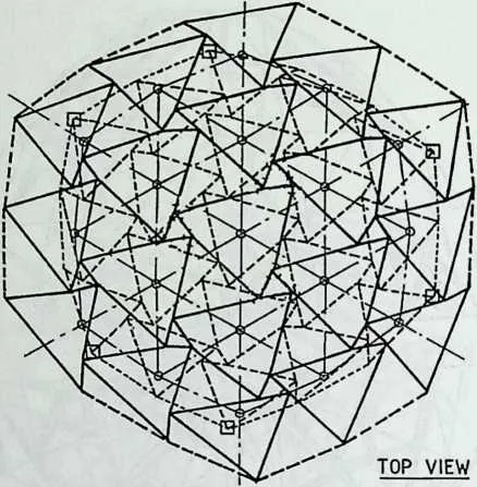
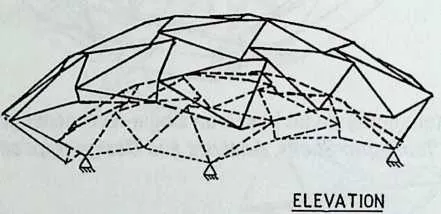
79 Figure 13.17 Double-layer tensegrity dome constructed using type la connection triangular truncated pyramids (only top and bottom cable layers shown). The dash-dot line represents the arch-grid, which is a geodesic subdivision of a hexagonal pyramid. (Source: A. Hanaor, ‘‘Geometrically Rigid Double-Layer Tensegrity Grids,’’ International Journal of Space Structures,\lo\. 9, No. 4,1994, pp. 227–238.)
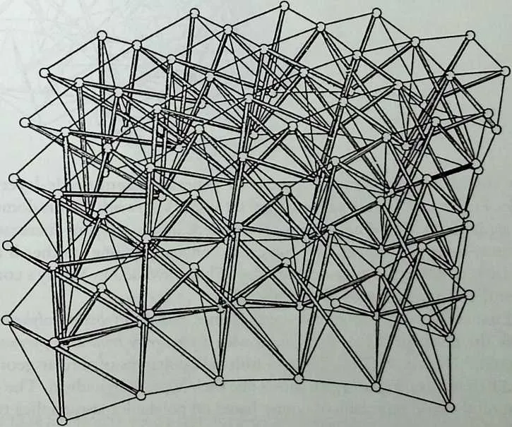
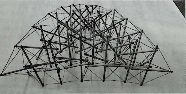
8182Double-layer surfaces of any shape, including flat surfaces, can be generated from double-layer networks based on T prisms or pyramids, as shown in Figures 13.10 to 13.13. Figure 13.17 shows a DLTG dome based on the triangular grid type la of Figure 13.11 (only top and bottom cable layers are shown).22 Although the pattern appears complex, the arch-grid forms a simple geodesic subdivision of a hexagonal pyramid. The arch-grid nodes indicate the locations of the centroids of the T pyramids constituting the dome. Figure 13.18 shows a model of part of a dome constructed on this basis.
83 Figure 13.18 Scale model of double-layer tensegrity dome segment using triangular truncated pyramids in type la connection.
85 LOAD RESPONSE
86 Geometric Rigidity
87 Referring back to the definition of tensegrity structures, tensegrity structures are prestressed cable networks, from the structural point of view. This implies that they are in most cases geometrically deformable. The terms geometric deformability and geometric rigidity require some explanation, as there is considerable confusion in terminology concerning this topic. The essence of the concepts is best explained by the simple prestressed cable structures shown in Figure 13.19. Figure 13.19/z shows a geometrically deformable prestressed cable. The deformability is expressed by the fact that the system cannot maintain equilibrium with the applied load in its original geometry. It must deform and change its shape in order to develop internal force components to balance the external load. The magnitude of the deformation depends primarily on the load and on the level of prestress—the tension force in the cable. It can be quite large, even for small load values. By comparison, the planar cable ‘‘network’’ of Figure 13.19£ (the cables are loaded in their plane) can maintain equilibrium in its original geometry, and its deformation is a result of elastic deformations (elongation and shortening) of the cables alone. These deformations are small in comparison to the geometric deformations of the cable of Figure 13.19a.
88 Some sources refer to geometrically deformable structures as ‘‘unstable,’’ but this is clearly a misnomer, because they are perfecdy capable of sustaining load, albeit at large deflections, compared with geometrically rigid structures such as trusses. Other sources refer to them as kinematically indeterminate, referring to the fact that the geometry changes depend on the load. A more rigorous discussion of this topic can be found in Pellegrino and Calladine.23
89 Most cable networks are geometrically deformable, including all tensegrity
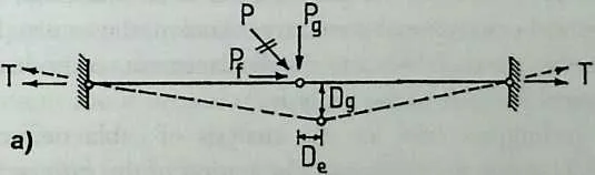
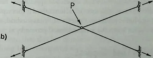
92 Figure 13.19 Illustration of geometric rigidity: (a) geometrically deformable prestressed cable, (b) geometrically rigid cable configuration.
93 configurations discussed up to this point, with the exception of the reinforced prism of Figure 13.6e. Geometrically rigid structures do not require prestress to maintain a reasonable stiffness. Some degree of prestress is nonetheless applied in cable networks, in order to ensure the tautness of cables. A geometrically rigid DLTG is described and discussed later (Figure 13.20#). Geometrically deformable networks are insensitive to inaccuracies in cable lengths. Tension in all cables is easy to maintain either by the shortening of a relatively small number of cables or by the elongation of bars. The inaccuracies in member lengths translate into deviations in the overall geometry. Geometrically rigid structures, on the other hand, are statically indeterminate. They can maintain equilibrium with the prestress force in the original geometry and do not adapt their geometry to compensate for changes in member lengths. Consequently, inaccuracy in bar or cable lengths may result in some slack cables. This tolerance sensitivity is a price that has to be paid for enhanced stiffness.
94 Features of Structural Analysis
95 A detailed discussion of structural analysis techniques for cable networks is beyond the scope of this chapter, but some general comments are warranted on the problems involved in analysis and design. Owing to the large deflections associated with geometrically deformable structures, nonlinear computational methods are needed, which are considerably more complex than the analysis of stiff, geometrically rigid structures such as trusses. Typically, the analysis of cable networks requires two phases. Phase I is a shape-finding procedure aimed at determining the equilibrium geometry of the network under prestress. Except in some special cases (such as tensegrity prisms and simple polyhedra), the initial geometry is not known, as it depends on the prestress. An initial geometry is assumed close to the desired final shape, prestress is then applied, and the new geometry is found in an iterative procedure. If this geometry is not satisfactory, the prestress has to be modified, and the process resumed. Once the prestressed geometry is known, the external load is applied and the forces in the members and the displacements of nodes are computed. This constitutes phase H of the analysis.
96 Several techniques exist for the analysis of cable networks. Levy and Spillers give a concise yet rigorous presentation of the stiffness method for geometrically nonlinear structures, including cable networks (computer programs implementing the algorithms are also presented).24 Barnes presents the principles of the dynamic relaxation method, developed specifically for tension structures (cable and membrane structures).25 This method is more powerful in dealing with highly nonlinear problems than the stiffness method, which may have convergence problems when the assumed initial geometry is greatly in error.
97 Characteristics of Load Response
98 As mentioned previously, very few studies—analytical and experimental—have been carried out on real-scale prototypes. Such studies are essential for the assessment of the concept of tensegrity structures and of the range of its feasible or practical applications. Two such studies are presented in the following sections, illustrating both the strengths and the weaknesses inherent in the concept of tensegrity.
99 Analytical Study
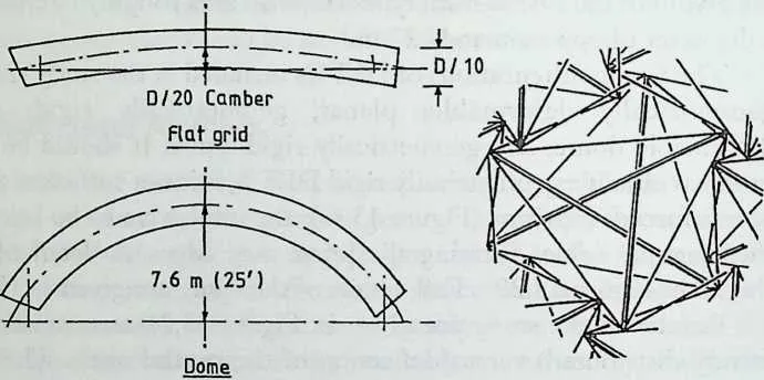
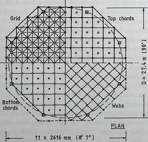
100 The study by Hanaor involves the full design, including nonlinear analysis (using the stiffness method), of several types of DLTGs of the triangular type la geometry (Figures 13.10 and 13.11).26 To facilitate the assessment of tensegrity structures in comparison with ‘‘conventional’’ space structures, a space truss of similar dimensions is also designed. The truss is a square-on-square offset double-layer grid (DLG). Figure 13.20/z shows the dimensions and layout of the DLTGs. Only the arch-grids are shown for clarity. Figure 13.20b depicts the layout of the DLG. Both types cover an area roughly circular in plan, with a diameter of approximately 27 m.
101 The four configurations of DLTGs included in the study are: planar (flat), geometrically deformable; planar, geometrically rigid; geometrically deformable dome; and geometrically rigid dome. It should be noted that in order to obtain a geometrically rigid DLTG, it is not sufficient to join together reinforced T prisms (Figure 13.6e); the units have to be laced together by the diagonal cables forming the prism side edges. A detail of the lacing is shown in Figure 13.20/z. Full details of the study are given in Hanaor.27
102 Results of the study are given in Figure 13.21 as normalized load (uniformly distributed) versus deflection of the central node. The abbreviations used in Figure 13.21 to denote the four DLTG configurations consist of two letters. The first letter denotes the geometry: P—planar (flat); D—dome. The second letter denotes the geometric rigidity: R—rigid; F—deformable (flexible). The curves represent the stiffness of the structure. The stiffness of deformable DLTGs depends on the level of prestress. The average level of prestress in bars was assumed as approximately half the capacity of the bar (initially assuming constant bar cross section).
103 Table 13.1 presents the relative unit weight (weight per unit surface area) of the structure, without the covering, with the DLG serving as control. This value may represent the structural efficiency of the system (the lower the value, the higher the efficiency).
104 It can be observed from Figure 13.21 and Table 13.1 that all DLTG configurations are considerably less stiff than the truss, and that all but the configuration marked with an asterisk have lower structural efficiency. The reason for the low structural efficiency is the length of the bars, as compared to the length of the bars in the truss (maximum forces are of the same order). The configuration marked with an asterisk relates to the rigid dome, with bars restrained against buckling at their midlength (e.g., by joining them together at this point). It can be seen that this has dramatic influence on structural efficiency.
105 Relatively long bars (compared with the length of cables) is a feature of all tensegrity structures encountered in the literature—refer to all figures. Unless this problem is addressed, it appears that structural inefficiency’ is inherent in tensegrity structures, at least those with no bar-bar connections. It is not a trivial matter, for instance, to restrain midpoints of bars in the DR*
106 CROSS-SECTION OUTLINES DETAIL OF
107 RIGID CONNECTION
108 Figure 13.20 Grids for analysis/design study: (a) double-layer tensegrity grid configurations, (b) double-layer grid space truss.(Source: A. Hanaor, ‘‘Geometrically Rigid Double-Layer Tensegrity Grids,’’ International Journal of Space Structures, Vol. 9, No. 4, 1994, pp. 227–238.)
110111b


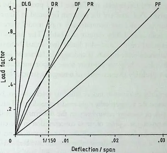
114 Figure 13.21 Normalized load-deflection curves of grids in design study. (Source: A. Hanaor, ‘‘Geometrically Rigid Double-Layer Tensegrity Grids,’’ International Journal of Space Structures, Vol. 9, No. 4,1994, pp. 227–238.)
115 configuration, without actually joining the bars. In all fairness it should be noted, however, that the comparison between space truss and tensegrity structures may be somewhat misleading. For a start, it does not include the roofing weight, which in tensegrity structures is expected to be a fight membrane, nor does it include the walls and other nonstructural elements absent in the dome configuration. In addition, the range of overlapping applications for the two types of structures (where a selection has to be made) is expected to be narrow. A more appropriate comparison might be with ‘‘conventional’’ cable and membrane structures, where the weight of anchoring systems has to be included. A discussion of the merits, limitations, and range of applications of tensegrity structures forms the substance of the last section.
116 Experimental Study
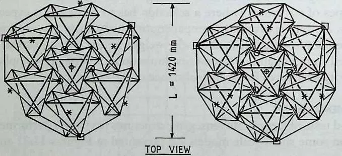
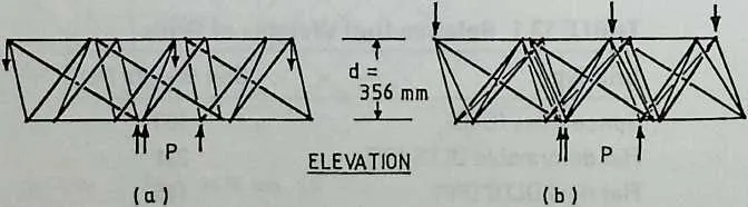
117 No load tests of large-scale tensegrity structures have been performed to date. Tests on some small-scale models are presented in Figures 13.22 and 13.23.28
119120TABLE 13.1 Relative Unit Weights of Grids
|
124Grid Type |
125Unit Weight (%) |
|
126Space truss (DLG) |
127100 |
|
128Flat deformable DLTG (PF) |
129221 |
|
130Flat rigid DLTG (PR) |
131185 |
|
132Deformable dome (DF) |
133125 |
|
134Rigid dome (DR) |
135119 |
|
136Rigid dome* (DR*) |
13777 |
145146* Bars restrained at midlength.
147 Figure 13.22 presents the test models and Figure 13.23 presents the results as load-deflection curves. Full details of the tests can be found in Hanaor.29 One geometrically deformable and one geometrically rigid model were tested to failure. Failure in both cases was by rupture of a cable. The curves of Figure 13.23 present analytical curves (dash-dot lines) and actual behavior (solid lines). Although failure by cable rupture is undesirable (failure by bar buckling would be more ductile), it helps to illustrate some important features of the behavior, which are probably characteristic of tensegrity structures:
- The geometrically deformable model failed to reach the predicted load capacity, whereas the geometrically rigid model exceeded it. This is probably due to lack of member redundancy in the deformable configuration, with cable rupturing at a point of stress concentration in the connection. The statically redundant geometrically rigid configuration, on the other hand, allowed for some load redistribution as some bars buckled elastically.
- Both configurations, but particularly the deformable one, regained a substantial portion of their load-bearing capacity following cable rupture, even though this rupture amounted to the loss of a whole unit, representing one-seventh of the members in the structure. This feature is due to the way in which the structure is constructed of individual tensegrity units, with the rupture of one not affecting the integrity of others. In the geometrically rigid structure, this unit separation is somewhat compromised by the interlacing of units. This characteristic is an expression of
150 □ Support O Load point * Critical member
151 Figure 13.Z2 Double-layer tensegrity grids for load testing. (Source: A. Hanaor, ‘‘Geometrically Rigid Double-Layer Tensegrity Grids,’’ International Journal of Space Structures, Vol. 9, No. 4, 1994, pp. 227–238.)
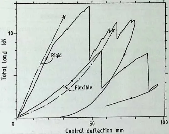
153 Figure 13.23 Load-deflection curves of tested tensegrity grids. (Source: A. Hanaor, ‘‘Geometrically Rigid Double-Layer Tensegrity Grids,’’ International Journal of Space Structures, Vol. 9, No. 4,1994, pp. 227–238.)
155156structural redundancy (as distinct from static redundancy or indeterminacy), which is a major factor in avoiding progressive collapse.
157 ASSESSMENT
158 Evaluation
159 Table 13.2 presents an evaluation of tensegrity structures, in terms of positive and negative features, based on current knowledge and understanding. There is no attempt at assigning weight or significance to these features. The negative features probably constitute a major factor in the nonimplementation of the concept to date, but psychological and other nontechnical factors probably play a role as well.
160 Applications
161 In view of their peculiar features, both positive and negative, it is not expected that tensegrity structures will find widespread application, replacing more familiar structural systems. Implementation of the concept is expected to be limited to applications of unusual or exotic nature. Following are some applications where it is thought that tensegrity structures could provide a viable and effective solution:
- Large open spaces with light or translucent coverings, such as swimming pools, conservatories, covered ‘‘outdoor’’ cafes, and other public spaces.
- Temporary, dismountable structures, such as exhibition halls, temporary storage facilities, and hangars.
- Deployable (i.e., folding/unfolding) structures, such as mobile reusable
|
TABLE
13.2
Evaluation
of
Tensegrity
Structures
| |
|
165Positive Features |
166Negative Features |
|
167Geometric variety and intricacy 168Light, intriguing appearance 169Absence of massive anchorage systems 170Simple (bar-cable) connections 171High structural redundancy 172Low tolerance sensitivity (connections in tension) 173Convenient deployability |
|
188189exhibition and display spaces; temporary shelters for various functions (celebrations, festivals, etc.); shelters in inaccessible places; and deployable structures in space.
- Additional, emergency support for air-supported structures to allow for unusual loading, such as asymmetrical snow loads, loss of pressure, and rupture.
- Exotic architectural features where dramatic visual effects are sought.
190 Implementation
191 Two of the negative features of tensegrity structures mentioned in Table 13.2 are a lack of complete understanding and some unresolved questions. Some of these questions have to be resolved and practical solutions provided for implementation in actual, functional structures. Following are a few of the more immediate requirements that come to mind:
- There has been very little work done on the roofing/surfacing material for the structures. It is recognized that in most cases the surfacing has to be fabric or other flexible material, yet most of the surfaces of structures proposed to date consist of planar facets. Such facets are unsuitable for fabric covering, which requires surfaces of negative Gaussian curvature (saddle shaped). How such surfaces are to be achieved is a question that requires thorough investigation and may fundamentally affect the geometric design of these structures.
- The incorporation of surfacing material affects other topics such as loading and structural analysis. It also offers the challenge of trying to use the fabric in a system to stabilize bars against buckling. Bar buckling is another major problem requiring a solution that will not detract from any of the concept’s main assets, such as its eerie ‘‘floating bars’’ appearance.
- Deployability is another topic that has received little attention. It may yet prove to be one of the main, if not the principal, assets of the concept, yet very little thorough research has been done into its theory and technology. Figure 13.24 presents a small deployable model.30 The
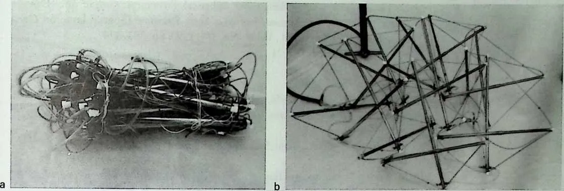
194195Figure 13.24 Deployable tensegrity dome model: (ajfolded, (b)deployed.
196model was constructed under primitive conditions, yet it proved to be quite efficient. It consists of telescoping bars with O-ring seals. When bars are contracted, all cables are slack and the structure collapses into a bundle (Figure 13.24/?). Deployment is by means of air pressure (supplied by a bicycle pump in this case) applied into the bars’ outer tubes by means of thin flexible tubes laced between them. Deployment was quite smooth with the flexible bars easily compensating for any inaccuracies in construction.
197• Although such simple models demonstrate the inherent deployability of the concept, there are many technical problems to be overcome. The effect of scale is of critical importance in mechanical devices in general. A major advantage of the present device is that it is self-adjusting and free of the problem of accumulating ‘‘free-play,’’ which plagues bar-folding structures. Nevertheless, means of adjusting the final geometry and providing adequate prestress are needed. The possibility of cable entanglement and its prevention also needs investigation. Another scale problem is the effect of cable stiffness and joint dimensions. Incorporation of roof covering adds another level of complexity to the deployment problem.
198 With these and other questions in mind, it can be said that the concept is long overdue for its first full-scale implementation in a highly visible prestigious architectural project.
13.2 NOTES
- 1.
- R. B. Fuller, Synergetics, Explorations in the Geometry of Thinking, Macmillan, New York, 1975.
- 2.
- R. B. Fuller, ‘‘Tensile-Integrity Structures,’’ U.S. Patent 3,053,521, Nov. 13,1962.
- 3.
- R. B. Fuller, ‘‘Non-Symmetrical Tension-Integrity Structures,’’ U.S. Patent 3,866,366, Feb. 18, 1975.
- 4.
- Fuller, Synergetics, p. 372.
- 5.
- D. G. Emmerich, ‘‘Self-Tensioning Spherical Structures: Single and Double Layer Spheroids,’’ International Journal of Space Structures (Special Issue on Geodesic Forms), T. Tamai, ed., Vol. 5, No. 3/4, 1990, pp. 353–374.
- 6.
- Fuller, U.S. Patent 3,053,521.
- 7.
- Ibid.
- 8.
- Fuller, Synergetics, p. 408.
- 9.
- Fuller, U.S. Patent 3,866,366.
- 10.
- H. Kenner, Geodesic Math and How to Use It, University of California Press, 1976.
- 11.
- Fuller, Synergetics.
- 12.
- Emmerich, ‘‘Self-Tensioning Spherical Styructures.’’
- 13.
- Ibid.
- 14.
- O. Vilnay, ‘‘Determinate Tensegric Shells,’’ Architectural Science Revue, Vol. 22, No. 2, June 1979, pp. 39–43.
- 15.
- A. Hanaor, ‘‘Double Layer Tensegrity Grids,’’ in Studies in Space Structures, H. Nooshin, ed., Multi-Science, Brentwood, 1991.
- 16.
- R. Motro, ‘‘Tensegrity Systems and Geodesic Domes,’’ International Journal of Space Structures (Special Issue on Geodesic Forms), T. Tamai, ed., Vol. 5, No. 3/4, 1990, pp. 341–351.
- 17.
- D. G. Emmerich, ‘‘Absolute Minimal Self-Tensioning Configurations,’’ Space Structures 4, G. A. R. Parke and C. M. Howard, eds., Proceedings of the Fourth International Conference on Space Structures, University of Surrey, England, Thomas Telford, London, 1993, pp. 998–1007.
- 18.
- Fuller, Synergetics.
- 19.
- R. Grip, ‘‘The Correspondence Between Convex Polyhedra and Tensegrity Systems: A Classification System,’’ International Journal of Space Structures (Special Issue on Tensegrity Systems), R. Motro, ed., Vol. 7, No. 2, 1992, pp. 3115–3125.
- 20.
- O. Vilnay, Cable Nets and Tensegric Shells, Analysis and Design Applications, Ellis Horwood, New York, 1990.
- 21.
- Emmerich, ‘‘Self-Tensioning Spherical Structures.’’
- 22.
- A. Hanaor, ‘‘Geometrically Rigid Double-Layer Tensegrity Grids,’’ International Journal of Space Structures, Vol. 9, No. 4, 1994, pp. 227–238.
- 23.
- S. Pellegrino and C. R. Calladine, ‘‘Matrix Analysis of Statically and Kinematically Indeterminate Frameworks,’’ International Journal of Solids and Structures, Vol.
20220322, 1986, pp. 409–428.
- 24.
- R. Levy and W. R. Spillers, Analysis of Geometrically Nonlinear Structures, Chapman and Hall, New York, 1995.
- 25.
- M. R. Barnes, ‘‘Forms and Stress Engineering of Tension Structures,’’ Structural Engineering Review (Special Issue on Tension Structures), M. R. Barnes and B. H. V Topping, eds., Vol.6, No.3/4, 1994, pp. 175–202.
- 26.
- Hanaor, ‘‘Geometrically Rigid Double-Layer Tensegrity Grids.’’
- 27.
- Ibid.
- 28.
- Ibid.
- 29.
- Ibid.
- 30.
- A. Hanaor, ‘‘Double-Layer Tensegrity Grids as Deployable Structures,’’ International Journal of Space Structures (Special Issue on Deployable Space Structures), S. Pellegrino, ed., Vol. 8, No. 1/2, 1993, pp. 135–143.