
7 Double Curvature Space Frames Supported on Four Points: Design and Construction of the International Plaza of Portopia ‘81
2Masao Saitoh
7.1 INTRODUCTION
3Port Island, which is off the coast of Kobe, is the first large-scale man-made marine city in the world. It has an area of 436 ha in which a hundred baseball stadiums could entirely be laid out. Fifteen years after the reclamation work began, major urban facilities such as hotels, hospitals, residences, and parks, as well as a fully automated mass-transit system, were completed in 1981.
4 The exhibition, called PORTOPIA’81, to commemorate the completion of Port Island was held during a 180-day period beginning March 20, 1981, in an area of about 65 ha in the south of Port Island (Figures 7.1 and 7.2). The
5 Beyond the Cube: The Architecture of Space Frames and Polyhedra, edited by J. Francois Gabriel ISBN 0–471–12261–0 © 1997 John Wiley & Sons, Inc.
6 □ 211
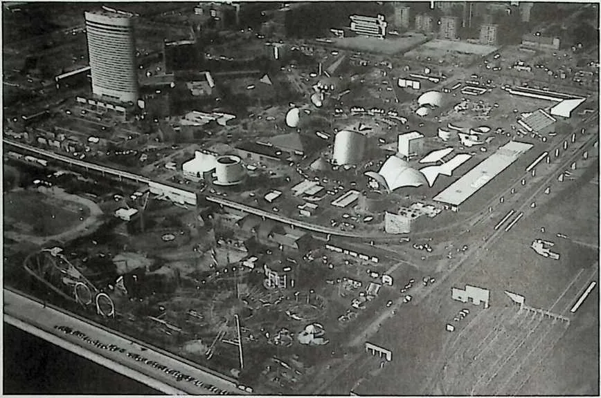
8 Figure 7.1 Aerial view of P0RT0PIA'81.
1011main theme of the exhibition was ‘‘Creation of a New Marine City of High Culture’’ with the aim of presenting an ideal future-oriented marine city as well as promoting international friendship and peace. The International Plaza was plarmed as the main facility for the exhibition.
12The International Plaza is an open space for events in which an octagonal space shelter covers the spectators’ seats. In this plaza such international events as dances, choral concerts, and dramatic presentations were held every day during the entire period of the exhibition. Sixteen hundred spectators’
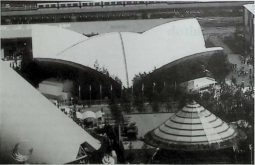
14 Figure 7.2 Aerial view of International Plaza.
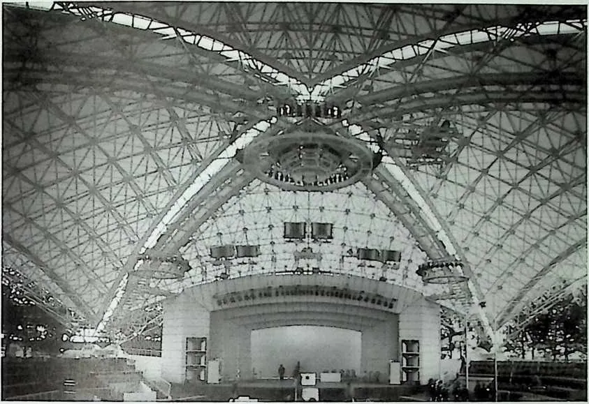
16 Figure 7.3 Interior view of space frame.
17 seats and a stage with a width of 18 m and a depth of 8 m were installed around an open space with an area of 700 m1 2 . The plaza had a seating capacity of 2,600 with the addition of movable seats from the adjacent vacant lot. The shelter that covered the International Plaza was in the shape of four triangular eaves connected to a central elliptical paraboloid shell, giving the appearance of open flower petals. The plan of the shelter was a square with sides of about 51m and was supported by hinges at the center of each side.
20 The spectators’ seats and the stage were designed to be enclosed under one roof. At the same time, the external shape was designed so that many people would be interested in entering the plaza. The shape chosen for the International Plaza was arrived at after a survey of shapes having either a static and closed image of an internal space or a dynamic and expansive image of an external atmosphere (see Figure 7.3). Both the shelter and the International Plaza were removed after the end of the exhibition.
21 OUTLINE OF THE STRUCTURE
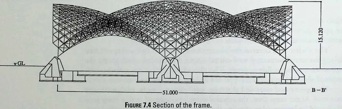
22 In order to realize a column-free large-scale roof with an area of about 2,600 m2, which possesses the shape of such a unique doubly covered surface, a double-layer space truss structure composed of a system truss was employed (Figure 7.4). This structure was chosen for the following four reasons:
- 3.
- Manufacturing accuracy of members is high owing to the fact that they are made in a factory with a dimensionally controlled production system.
- 4.
- A short construction period is possible.
2728The roof truss consists of upper and lower layers with a two-way square grid of about 2 m and a depth between layers that varies from 1 to 2 m. The TM (Taiyo-Mero) system adopted for this roof has 5,600 steel tubes for the chords and web members and 1,560 steel nodes for its joints. The self-weight of the roof truss is about 85 tons corresponding to 33 kg/m2 and the long-term design load is estimated at 50 kg/m2, including the weight of the roof fabric.
29In general, the structural design followed the flow diagram shown in Figure 7.5. It is important to note that there are two phases, a preliminary design to decide the structural system and a final design to examine the structural behavior.
30Architectural
31Requirement
- image & function •scale
- boundary
32 t
33 ( Structural Form )<■
34 4
35 Internal Structure -. system of internal str.
- strength and stiffness
36 of subassemblies
- arrangement
37 / unit, pattern \
38 \ depth, frequency /
39 4
40 ( Structural System )
41 Form Finding
Method
42 . geometrical
43 . mathematical
44 . experimental
45 -Connection -
- joint mechanism
- statical property
- eccentricity
46 Analytical Method
- theoretical
- numerical
- experimental
47 Structural
48 Analysis ~
- stress analysis
- stability analysis
49 . limit analysis
- dynamic analysis
5152Additional Load
53 dead & live
54 snow wind earthquake temperature erection
55 support movement
56 ( Structural Behavior )


58 ’’
- internal str.
- joint str.
- boundary str.
59 Design of
Structural Element
60 Figure 7.5 Structural design flow of space frame.
61 STRUCTURAL PLANNING
62 During the design of the space frame, attention was paid to three basic factors:
- 1.
- Form
- 2.
- Arrangement
- 3.
- Connections ‘‘Form’’ is the shape of the overall space frame, ‘‘arrangement’’ in the internal structure means the arrangement of the individual members consisting of several elements, and ‘‘connections’’ refers to the joint system of the space frame. When the support conditions and the perimeter conditions of the space frame are predetermined, its structural properties are determined by the factors mentioned previously. In this chapter we shall discuss form and arrangement.
64 Finding the Form
65 Finding the form of the roof surface is the starting point in the preliminary design of a shell structure. It is also the approach used in the design of a space frame and starts with a general form—a surface curved in space—which is then replaced with a similar structure composed of discrete elements.
66 Therefore, the technique for the form design of space frames is the same as the technique in the design of shell, tension, or pneumatic structures. Three methods of design can be distinguished: geometrical, mathematical, and experimental.
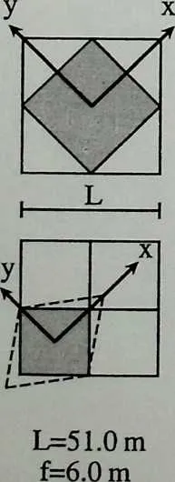
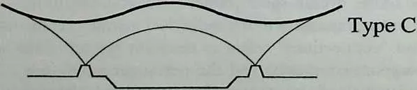
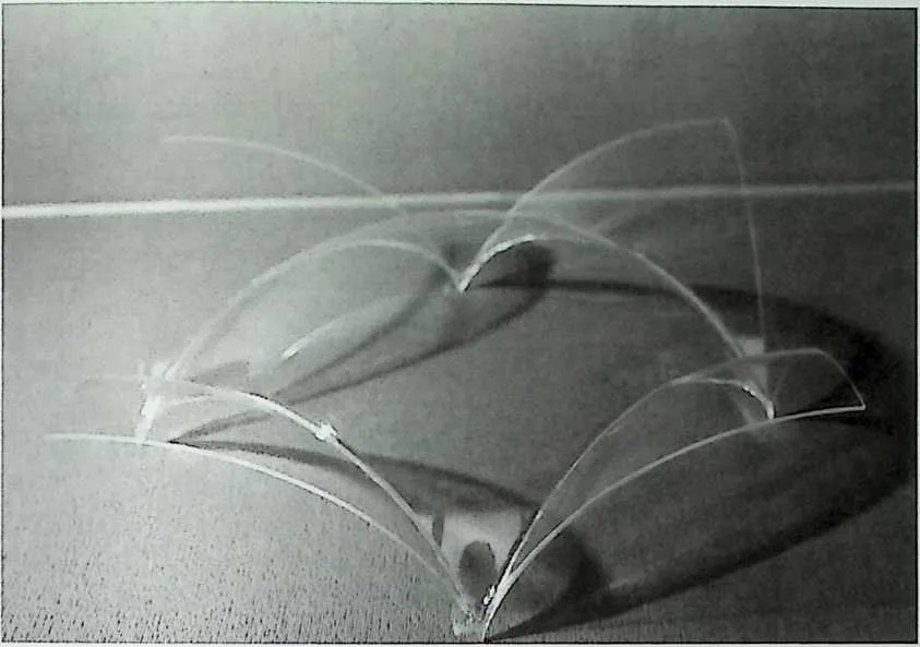
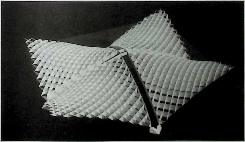
67 In this case, from the architectural point of view, the form was desired not only to provide the enclosed space for the audience but also to be attractive as monumental architecture. One can imagine a number of curved surfaces with four supporting points. Here, the author proposed three forms of shells, characterized by the curved edge line as shown in Figure 7.6.
68 Type A has four wing shells spread from a central dome, type B is obtained by the combination of four hyperbolic paraboloid surfaces, and type C is the continuous surface as a whole having both properties of types A and B. Types A and B are pure geometrical surfaces and type C is a free form that can be determined mathematically or by experimental methods such as by hanging a weighted net.
69 To compare the structural behavior of the proposed form of types A and B (Figures 7.7 and 7.8), stress and displacement analyses were carried out for the case of self-weight, which is dominant in large-span space frames. Using the finite-element method of numerical analysis, units are replaced with equivalent beam sections. Consequently, the effective stiffness in tension and
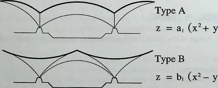
71 Figure 7.6 Proposed form of the roof.
73 Figure 7.7 Model of Type A.
74 bending and shearing of two kinds are measured in the unit and are put into the equivalent beam that makes up the grid surface of the shell roof.
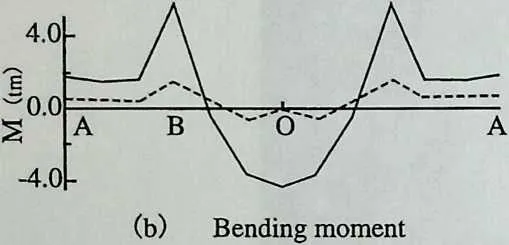
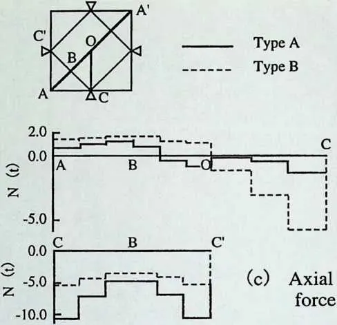
75 Figure 7.9 shows the results of calculations using the equivalent-grid model. Both the deflection and the bending moments of type B shells are smaller than those of type A. On the other hand, the axial force along OC is larger in type B than in type A. From these results, type B behaves more like a membrane than type A.
76 After considering the architectural requirements, especially the creation of a theater-like space, type A (composed of transitional surfaces of an elliptical paraboloid) was adopted for the actual shell roof.
78 Figure 7.8 Model of Type B.
79 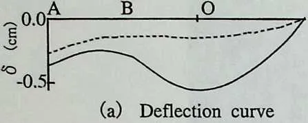
 Transition to the Curved Surface
80 Figure 7.9 Comparison of Types A and B.
81 In order to comprehend the structural effect obtained by the curvature in the type A shell, the models that demonstrate the stages of development, starting with a plate to arriving at a final structure, are presented in Figure 7.10.
82 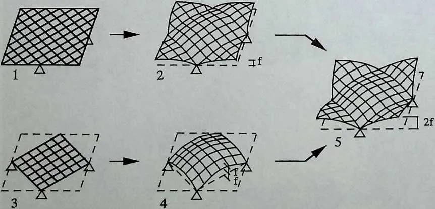 Each stage of the models was subject to uniform loads (50
kg/m3
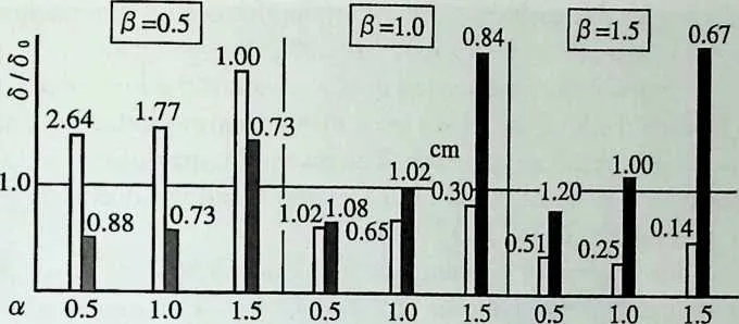
4
) and
the structural behavior was calculated by the equivalent-grid method. The following
Each stage of the models was subject to uniform loads (50
kg/m3
4
) and
the structural behavior was calculated by the equivalent-grid method. The following
7.2 CONCLUSION
85s are drawn from the deflection and bending-moment distribution (Figure 7.11):
86 Figure 7.10 Five stages in the development of the shell.
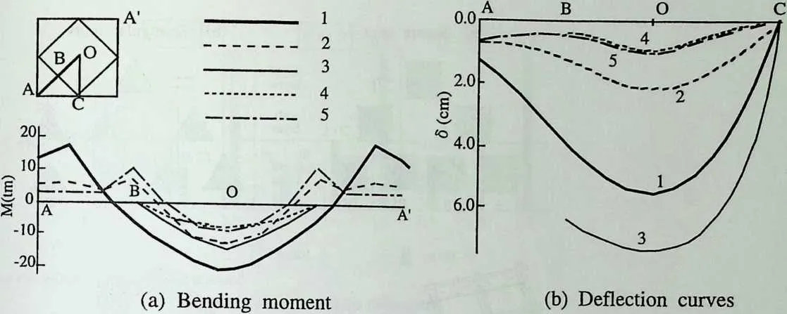
88 Figure 7.11 Transition of the structural behavior.
- 2.
- The apparent effects of the curvature in shell structures can be seen in the deflection of stages 2 and 4.
- 3.
- Because the change in deflection is only slighdy different between stages 4 and 5, the structural rationality of stage 5 to cover a larger area is evident.
90 Member Arrangement
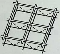
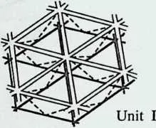
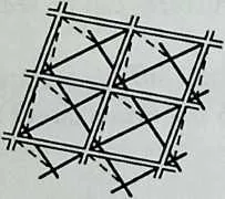
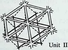
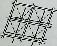
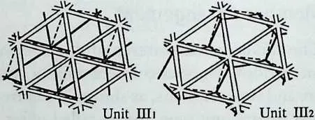
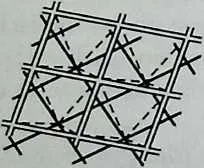
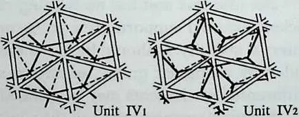
91 The fundamental patterns of double-layer space frames can be obtained geometrically by various combinations or arrangements of the upper and lower layers and web elements, as shown in Figure 7.12. Unit HI, which is the most popular square unit type, the so-called offset grid, was adopted for this structure.
92 Because this unit has no twisting rigidity and is not internally stable, sufficient external supports have to be provided to compensate for the lack of internal stability. It should be noted that with internal stability (such as is provided by triangular grids) additional stresses during construction or due to differential settlements may be avoided.
93 Member arrangement and the constituent frequency (the scale ratio of the element dimension to the overall dimension) determine the stiffness and the load-carrying capacity of a space frame.
94 For the purpose of studying the influence of depth and frequency on structural behavior, a numerical analysis was carried out for the unit models as shown in Table 7.1. In this table the frequency ratio and the depth ratio for the basic unit used in the realized structure are presented as a (the ratio of unit frequency) and Ji (the ratio of unit depth) respectively. The numbers in parentheses represent the ratio of total volume of truss members used in the whole structure.
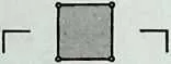
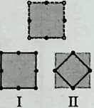
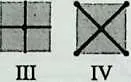
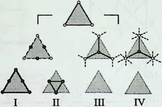
95 The analytical method used was the one mentioned earlier and only the effective rigidities are changed for the beams of the grids of the shell. Figure 7.13 shows the deflection at points A and 0 in nondimensional units with a=y?=1.0.
96 (a) Square units
97 (b) Triangular units
98 upper layer
99 web layer
100 lower layer
101 Unit
102 Unit n
103 Figure 7.12 Fundamental pattern of units.
104 Table 7.1 Analytical Models of Different Units.
|
2=
|
a (b/bo)
| |||
|
1100.5 |
1111.0 |
1121.5 |
||
|
114un o |
115Q—9 116V (2.00) |
117■(0.85) |
118w (0.55) |
|
|
120o 121T-—< |
122T7 y (2.74) |
123V(1.00) |
124q p 125\ (0.60) ¥ |
|
|
126CQ. |
127v-~< |
128V7 129V (3.53) |
130Sms) |
1319 P 1321 / 133\/(0.67) |
140 b



143 point A | point O
144 So: the deflection of the basic unit at point 0
145 Figure 7.13 Comparison of the deflection.
146 In this figure two numbers are shown: the deflections for each case divided by the deflection of the basic unit at point 0 and the actual values of deflection.
147 As the depth ratio / becomes large, the deflection decreases considerably and the point of maximum deflection moves from point A to 0, corresponding to increasing bending rigidities.
148 The economical efficiency concerning the depth and frequency is difficult to estimate. Although the deflections have a tendency to decrease as a and Ji increase, care should be taken to ensure that the tolerable force due to buckling decreases simultaneously.
149 NUMERICAL ANALYSIS OF THE SPACE TRUSS SHELL
150 Static Analysis
151 The structure was analyzed as a grid framework in the preliminary design to select the form and member arrangement of the structural system. A final calculation was made using the displacement method, assuming a hinged connection at every intersection of the truss elements. Axial forces on truss members and the deflection of all points were numerically obtained under dead load (50 kg/m2), horizontal earthquake force (seismic coefficient = 0.3) and wind force (v = 35m/sec). Wind tunnel tests were performed on a 1/100 scale model to obtain the design loads.
152 Because the roof is fight and an open-air type, the wind force has considerable influence on its structural behavior. The maximum tensile axial force of truss members due to wind forces was 4.6 times as large as that due to dead loads.
153 Furthermore, for the case of temperature forces, the elongation of the tie beam and differential settlement of the supports were examined.
154 Dynamic Analysis of the Roof
155 The dynamic analysis for seismic forces was carried out using a model composed of 85 nodal points and 168 equivalent beams. A lumped mass system was adopted for this analysis, and the damping factor and the maximum acceleration were assumed to be h = 0.02 and 200 gal respectively .
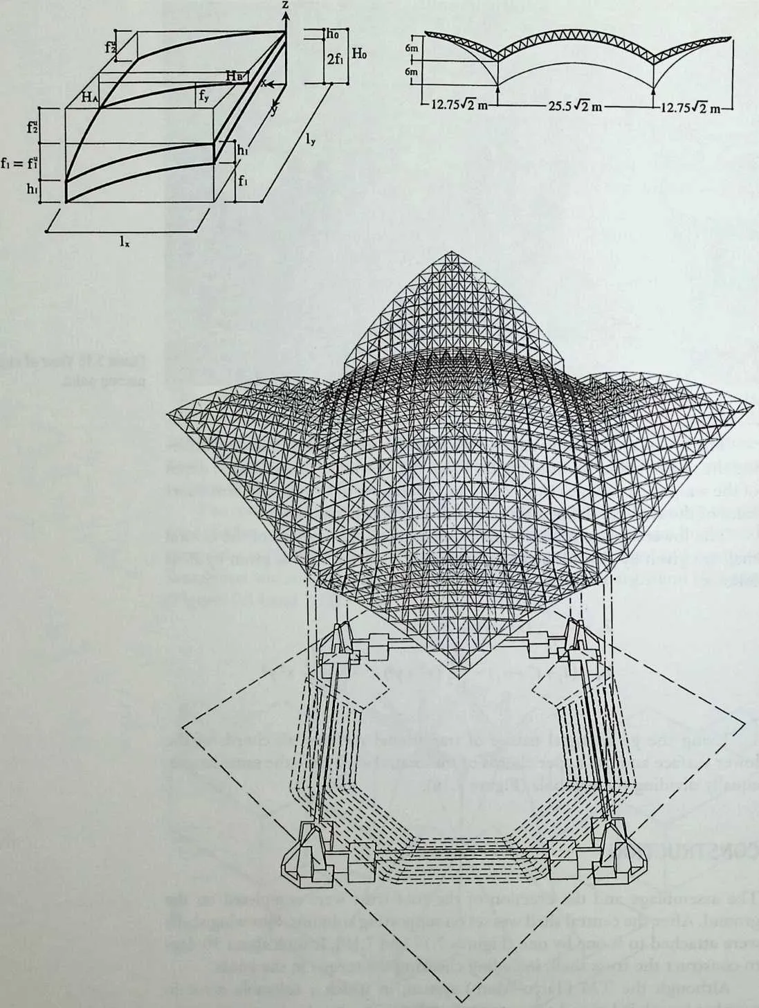
156 For a comparison of the vertical displacement of the influence coefficients given by each method, the RMS (root mean square) method of analysis was used based on a response spectrum. The maximum magnification of acceleration response is 8.43 (EL CENTRO UD 1940) and the maximum deflection is 14.2 mm (MIYAGIOKI UD 1978).
157 The distribution of bending moments was obtained from the above response displacement by means of the replacement method with equivalent beam. It is important to emphasize that the axial forces in this case are very large. That is, the maximum force of 15.6 ton corresponds to a magnification of 10.9 of the one due to horizontal earthquake forces (seismic coefficient = 0.3) and 0.96 of the one due to wind forces (q= 148 kg/m2; return period = 30 years).
158 STRUCTURAL DESIGN
159 The member size of the steel tubes used in the roof are of eight kinds, 114.34>X6.0 to 48.6<J>X3.2, with slenderness ratios of about 50–100, 80–120, and 60–130 for upper chords, lower chords, and diagonal members, respectively. The ball joints used for the intersections have five different diameters ranging from 150c|> to 85<j>.
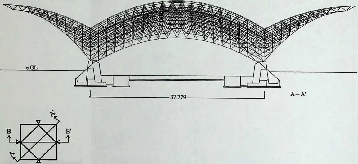
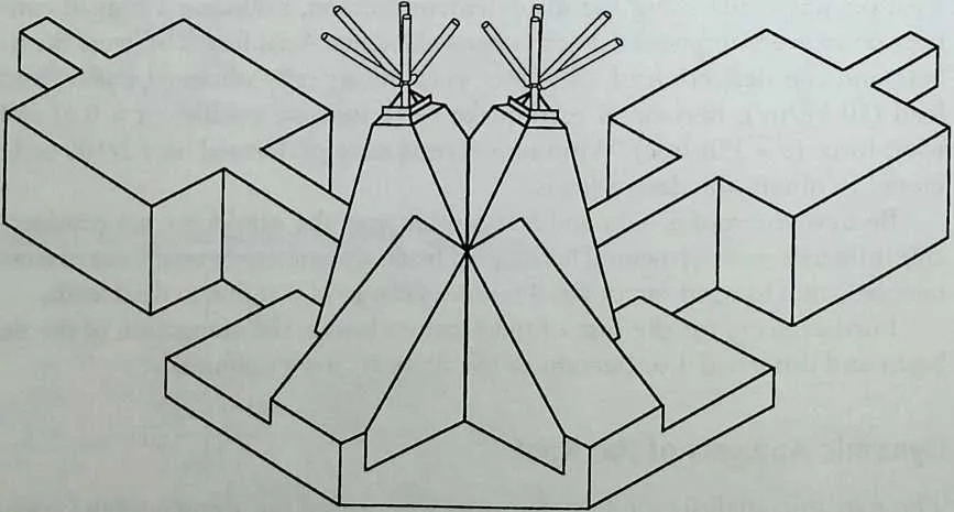
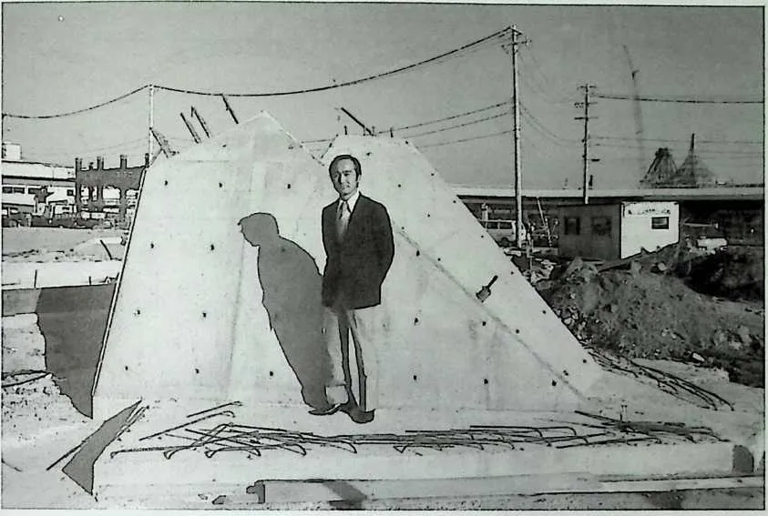
160 The roof has eight supporting pin joints at the lower chords sitting on the four reinforced concrete supports. To resist the rotation due to the horizontal thrust of wind or earthquake, these supporting columns are fixed to a complex foundation and are also connected to each other by an underground tie beam (Figures 7.14 and 7.15).
163164Figure 7.14 Supporting point.
165 Figure 7.15 View of supporting point.
167 The catwalks for maintenance were provided in the space frame by utilizing the space within the roof depth. From the viewpoint of statics, the depth of the wing shell changes from 2 to 1 m. Therefore, the upper and lower surfaces of the roof are defined by two kinds of elliptical paraboloid.
168 The lower surface of the whole roof and the upper surface of the central shell are given by Zo and the upper surface of the wing shell is given by 7,\ as follows:
170171Zo = -—(x2 + y2) + 2f
172iy
173u f2
174Z1=(f1 + f‘‘+h1)--(x2 + y2)-z lyz
175 '1 A-J lx2ly2
176 Using the geometrical nature of transitional surfaces, all chords of the lower surface and the upper chords of the central shell have the same length, equally dividing the parabola (Figure 7.16).
177 CONSTRUCTION
178 The assemblage and the erection of the roof truss were completed on the ground. After the central shell was set on supporting columns, four wing shells were attached to it one by one (Figures 7.17 and 7.18). It took about 30 days to construct the truss shell, including checking the torque in the joints.
179 Although the TM (Taiyo-Mero) system, in which a tolerable error in member length is 1 mm, has no error-absorbing capacity, the construction was achieved without scaffolding or adjusting of the support position. The reason
182183Figure 7.16 Surface of the shell.
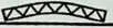
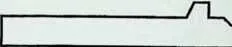
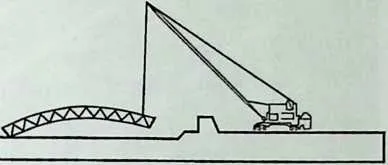
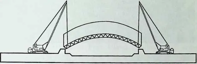
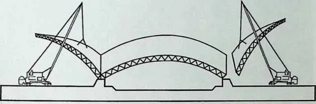
185 Figure 7.17 Process of the construction.
187188for adopting this construction method was because this structure is not too large and the unit of space frame used has no twisting rigidity. In the construction of a large-span space frame, particular attention must be paid to member deformation due to temperature change and self-weight.
7.3 CONCLUSION
190At present, many double-layer space truss structures of the type described in this chapter are being constructed. However, we often forget that this type of structure has low applicability to shapes formed by such permanent finishing materials as glass and membranes, although it can be freely formed as a structure. As for the roof finish, a membrane material was adopted and attached to each upper joint of the space frame. Sometimes the existence of secondary members to support finishing roof material seems to prevent the rationalization of a space frame in which all members are attached with pin joints.
191We live in an age when ‘‘any kind of shape can be formed’’ because of the remarkable development in computer and analytical technologies. It is now true that the degree of freedom for conceiving any design and shape seems to have become unlimited.
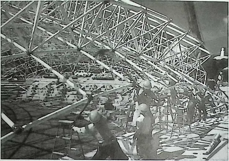
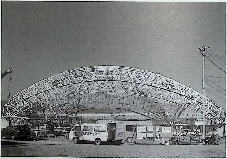
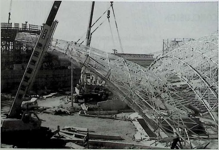
195 Figure 7.18 View of space frame during construction.
196 Consequently, a firm concept concerning the ‘‘integration of structure and design’’ must be established. As this chapter shows, a sound and attractive structure with a double-layer space truss can be developed based on this concept.
197 ACKNOWLEDGMENTS
198 The author wishes to express his sincere gratitude to the late Dr. Yoshikatsu Tsuboi and other colleagues who recommended this manuscript to the IASS, and for their fruitful discussions. This paper was completed in collaboration with Mr. Akira Okada, a research assistant at Nihon University. The author also wishes to thank the following organizations for allowing publication of this manuscript: Association of Port Island Exhibition of Kobe; Nikken Sekkei, Ltd., planners, architects, and engineers; Kajima Corporation, general contractor; Taiyo Co., Ltd., space frame contractor; Saitoh Laboratory, Nihon University, and TIS & Partners, engineering consultants; Kawamura Laboratory, Osaka City University, wind tunnel testing; and Tajimi Laboratory, Nihon University, vibration testing.