14 Visual Morphology of Space Labyrinths: A Source for Architecture and Design
2Haresh Lalvani
14.1 INTRODUCTION
3The spatial and visual appeal of morphological images is inescapable for architects, designers, and engineers willing to explore new geometries and structures for architectural space making and the fundamental order of space underlying structures across the disciplines. Such an order imposes itself upon every architect who experiments with geometry as a device for shaping and structuring space, and upon every engineer who searches for a morphologic basis of improved structural performance. Basic morphological principles are embodied at varying levels of complexity in architecture and in the design process itself. The knowledge of such principles is essential for architects willing to ‘‘create’’ lasting works that integrate the art with the science of architecture.
4 Beyond the Cube: The Architecture of Space Frames and Polyhedra, edited by J. Francois Gabriel ISBN 0–471–12261–0 © 1997 John Wiley & Sons, Inc.
5 □ 409
78This pictorial essay is put together to show a small fragment of the vast design resources offered by the study of morphology and design science. The examples shown here demonstrate the limitless scope of this new design field, which is in need of a comprehensive visual encyclopedia of morphology. An atlas of form and structure, noticeably absent in the field of architecture and design, can serve as a standard reference for architects, artists, designers, engineers, scientists, and mathematicians. Morphology provides the underpinnings of a taxonomy for such an atlas. Our work in the development of a unified morphological system of space structures provides a candidate model for such a taxonomy.
9In this chapter we illustrate excerpts from our morphological system by focusing on an interesting class of structures called space labyrinths, based on the author’s ongoing research on these particular structures.
10SPACE LABYRINTHS
11Reminiscent of the Cretan legend where the labyrinth designed by Daedalus was a single ‘‘sequential’’ linear space, the space labyrinths described here are ‘‘distributed’’ spaces in three or more dimensions. These labyrinths are spatial structures composed of a continuous surface (called a manifold) that divides space into two parts, one on the ‘‘inside’’ and the other on the ‘‘outside.’’ Seen as surfaces, these configurations are not unlike the commonly used boxshaped rooms in architecture or the familiar donut shape, with the essential difference that these space labyrinths are surfaces that are ‘‘open’’ and can be extended finitely as well as infinitely, whereas the box is a finite ‘‘closed’’ region of space. Three such structures were known to mathematicians in 193 71 and the concept was extended independently by Burt et al.,2 Pearce,3 and Schoen,4 and additional examples were developed by Lalvani.5 This catalog shows some of these and several interesting cases from new classes of labyrinths already mentioned in the author’s previous works. These include nonperiodic space labyrinths,6 -dimensional space labyrinths termed hyperlabyrinths) •’’ and hyperbolic labyrinths.9
12Space labyrinths are inherently interesting for architecture because of their continuously winding three-dimensional space. The first example of a built space labyrinth with curved surfaces is provided by Pearce’s structure for the Brooklyn Children’s Museum. Burt has suggested novel applications for very large span building structures.10 Our new periodic, nonperiodic, and higher-dimensional labyrinths provide alternative geometries for such large structural spans. In aquatic environments, the ‘‘outside’’ space of the labyrinth can accommodate the water displaced by the ‘‘inside’’ space, thereby providing a natural marriage of geometry with Archimedes’ buoyancy principle. Transformational labyrinths provide candidates for deployable and adaptable architecture, which changes its size and shape with changing needs.
13The study of space labyrinths is an active area in the sciences, especially in certain classes of biological structures, and it also provides new directions in crystallography. In macroscopic biological structures, the trabeculae of bones are among the common examples of irregular curved-faced labyrinths. The use of labyrinths at a micro level in nature is found in the structure of zeolites, which act as molecular sieves. Such sieves are filters that remove or trap undesirable substances. Recent applications to car filters, and spin-off applications to surfaces and ‘‘openings’’ of smart buildings that ‘‘breathe’’ or otherwise maintain homeostasis through a labyrinth membrane, are promising applications of micro space labyrinths to architecture.
14 SYSTEMATIC METAMORPHOLOGY
15 We have adopted Anne Tyng’s term metamorphology to define our approach to the systematic morphological classification and generation of form. We use the concept of higher-dimensional (72-dimensional) periodic tables, or hypertables. Our method permits an exhaustive classification, indexing, generation, as well as transformation, of a wide variety of space structures.11 Here, we show the use of this technique for the generation of labyrinths, both known and new. The chapter is, in most part, restricted to labyrinths that have a single type of vertex only. All vertices of such structures are identical, with each vertex having the same number of polygons and edges meeting at it in the same sequence. This restriction offers a convenient starting point for exploring the fundamental order of space and is, in addition, significant for modular building systems where identical components translate into economy in construction. For the purposes of illustration, we show structures composed of plane regular polygons, but the method extends to all of its topologic variants: curved-space labyrinths composed of curved polygons, nonperiodic labyrinths, labyrinths projected from higher dimensions, and labyrinths in non-Euclidean space. Some examples of these different types of labyrinths, most of them new, are shown toward the end of the chapter.
16 Regular Structures
17 The concept of hypertables is briefly recapitulated from our previous work and is followed by its application to space labyrinths. For 72-dimensional regular structures, characterized by the Schlafli symbol \p,q,r,s,…,u,v,ru)}, the hypertable is a hypercubic lattice of dimension 72-I, where each distinct regular structure occupies a different vertex of this lattice; for details, see Lalvam.12 In this space the structures are indexed by corresponding higher-dimensional Cartesian coordinates (p,q,r,s,…;u,v,'u)'). Three-dimensional structures {p,q}, comprising polyhedra, plane and hyperbolic tessellations, and characterized by/2-sided polygonal faces, q of which meet at every vertex, are indexed (p,q) and are arranged in a two-dimensional lattice with the integer p varying along one axis and the integer q along the other. Four-dimensional structures [p,q,r}, comprising four-dimensional polytopes, which are composed of cells {p,q} and vertex figures {q,r}, are indexed (p,q,r) and are arranged in a three-
|
21{3,3,5} 22600-cell |
23{4,3,5} |
24{5,3,5} |
|
25{3,3,4} 2616-cell |
30{5,3,4} |
|
|
31{3,3,3} |
32{4,3,3} |
33{5,3,3} |
|
345-cell |
358-cell |
36120-cell |
43 Figure 14.1 A portion of a three-dimensional lattice of four-dimensional polytopes designated by the Schlafli symbol {p, q, /}.
4546dimensional cubic lattice defined by the integer variables p, q, and r. And so on for higher-dimensional structures.
47Figure 14.1 shows a portion of a square lattice extracted from the three-dimensional cubic lattice of polytopes. This figure includes nine four-dimensional polytopes, which are indicated by their Schlafli symbol. Of these nine, five are finite structures in Euclidean space and include the simplex {3,3,3} (or 5-cell), the four-dimensional cube {4,3,3} (or 8-cell) and its dual {3,3,4} (or 16-cell), and the 120-cell {5,3,3} and its dual {3,3,5} (or 600-cell). The structure {4,3,4} is the simple cubic lattice, a degenerate four-dimensional structure, and the remaining three are structures in hyperbolic space. The computer-animated film Not Knot by Charles Gunn and Delle Maxwell and based on William Thurston’s work,13 shows the transformation of the structures in the last column on the right. Clearly, our hypertable system provides a basis for a multitude of such intertransformations between these and other structures within the hypertable.
48Semiregular Structures
49Semiregular structures, composed of more than one type of regular polygon meeting identically at each vertex of the structure, can be mapped in an extended hypertable. Each vertex of the hypertable of regular structures splits into n additional directions to accommodate 2’’ semi-regular structures; for details, see Lalvani.12 The extended hypertable is composed of regular and semi-regular structures and provides a starting point for generating space labyrinths. The structures in this space are indexed in binary combinations of 0’s and l’s or 0’s and X’s, where X is any integer for the number of stages (frames in an animation) in the transformation process between labyrinths. The index gives the location of each structure within the hypercubic lattice.
50Figure 14.2 shows the tetrahedral fundamental region PQRO of a fourdimensional polytope {p,q,r}. It is composed of six edges, which join the centers of a cell, a face, an edge, and a vertex to each other. The fines radiating from the cell center 0, the ‘‘radial’’ edges, are coded in three primary colors,
51 Figure 14.2 The tetrahedral fundamental region of a fourdimensional polytope in six edge colors orthree pairs of complementary colors.
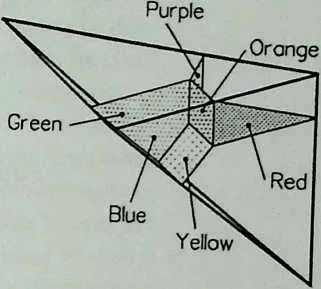
52 Figure 14.3 Six planes meeting at one vertex within the fundamental region; each plane is perpendicular to one of the six edges of Figure 14.2 and colored correspondingly.
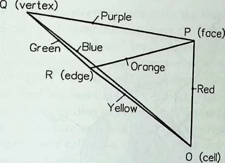
54 and the ‘‘circumferential’’ edges are coded in three secondary colors with the complementary colors coding the opposite edges.
55 Figure 14.3 shows portions of six dual planes (faces) meeting at a vertex within the fundamental region. The faces are defined by four different edges, each perpendicular to the face of the fundamental region. Each face plane is perpendicular to one of the six axes and colored accordingly; that is, a red plane is perpendicular to the red axis, and so on. Alternatively, a pair of complementary colors could be used to illustrate the line-plane duality. The six planes define the faces of a semi-regular polytope 1111 composed of four different cells. This is one of a family of 16 four-dimensional polytopes obtained by different combinations of the four different edges, with each edge corresponding to a different dimension of the hypertable. Within the fundamental region of each structure, the vertex occupies a distinct position different from the others. In fact, only 16 distinct positions are possible and hence 16 structures. Details of this organization have been described elsewhere for one family of structures corresponding to the simple cubic lattice {4,3,4} and referred to as family (43 4).7 The left-handed and right-handed ‘‘snub’’ structures require the introduction of two additional dimensions to the hypertable, one for left-handedness and the other for right-handedness.
56 The six planes defining the structure corresponding to Figure 14.3, and belonging to the cubic family (434), are shown in Figure 14.4. Its associated
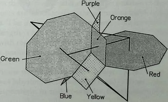
58 Figure 14.4 Six planes at a vertex located within the fundamental region of the simple cubic lattice {4,3, 4}, a degenerate fourdimensional polytope. The structure obtained this way is indexed 1111.
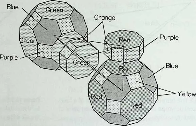
60 Figure 14.5 Four cells corresponding to the six planes of Figure 14.4, shown here in an exploded view.
61 four cells are shown in an exploded view in Figure 14.5. The entire set of regular and semi-regular structures of this family comprises a total of 16 structures and is illustrated in Color Art 6 in a four-dimensional hypertable; only four cells associated with a fundamental region are shown in an exploded view. This fundamental region, when repeated by symmetry operations, generates the complete structure which, in the example shown, is space filling. A portion of this space filling for each of the 16 structures is shown in Color Art 7. In
63 q=3
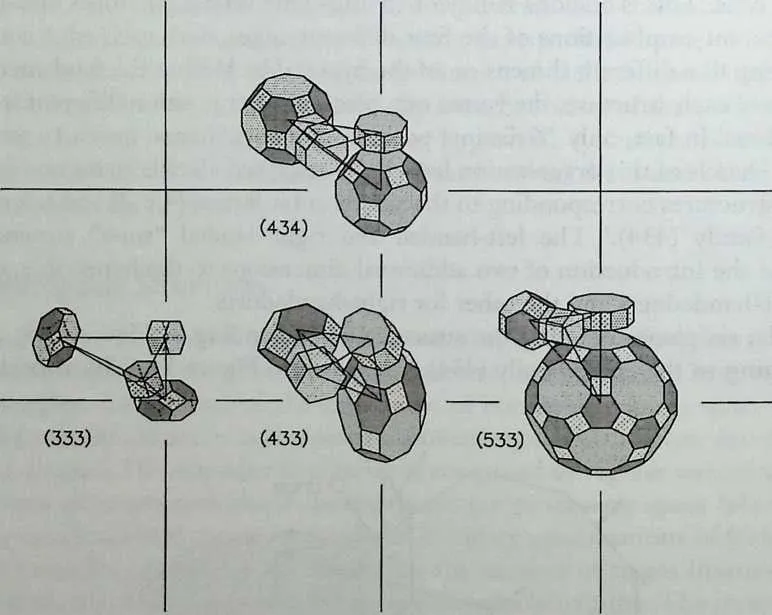
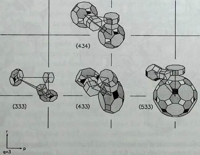
64 Figure 14.6 Structures 1111 of four families of polytopes corresponding to Figure 14.1 and arranged in a corresponding three-dimensional lattice; only a two-dimensional portion of this lattice is shown.
65 continually transforming structures the four edges ‘‘implode’’ and ‘‘explode’’ gradually in all combinations along the four directions of the hypertable generating all ‘‘intermediates’’ between these 16 structures. The intermediates are themselves interesting space structures as shown later with a few examples.
66 In Figure 14.6 the four cells of the semi-regular polytopes 1111 of four different families, families (333), (433), (533), and (434), are shown in a square lattice corresponding to Figure 14.1. The cells are shown in exploded views in each case and are analogous with one another. The corresponding faces of the corresponding cells have the same color and in each case the same six colors are needed. Color Art 7 and Figure 14.6 combined are part of a larger sevendimensional table that maps all the regular and semi-regular four-dimensional structures in one space.
67 LABYRINTH GENERATION
68 Families of space labyrinths, which divide space into two parts, can be derived from the families of regular and semi-regular structures by removing all faces in complementary colors. In fact, the removal of complementary colors is a convenient selection because any single color, or any combination of colors, could be removed to provide space structures composed of cells with different types of openings. This aspect of systematic face removal by color was addressed by Lalvani.11 Clearly, labyrinths, where only two complementary-colored faces are removed, are special cases in such an extended family of space structures produced from each source family.
69 Cells of one family of labyrinths belonging to the cubic family (434) are shown in Color Art 8 in an exploded view. Here, red and green faces are removed from the cells of structures in Color Art 6. Several ‘‘degenerate’’ labyrinths, composed of isolated closed cells, are produced in the process. Of the 16 structures generated this way, 9 are ‘‘legitimate’’ labyrinths having a continuous interior space. The cells of these are shown in Figure 14.7 in a portion of the hypertable. The same nine structures are shown as cubic portions of a space-filling array in Color Art 9; in this illustration the continuous surfaces of the labyrinths can be better appreciated.
70 One of the four two-dimensional tables, each defined by a different face of the hypertable and embedded in Color Art 9, is shown in Color Art 10. In addition to the structures lying at the vertex positions of the table, intermediate structures are added to show the continuous transformations between the labyrinths. The intermediates preserve angles but have more than one different edge length. They also provide visually and spatially interesting variants of the ones with regular faces only. Close-up views of three labyrinths located at the vertex positions in Color Art 10 are shown in exploded views in Figures 14.8 to 14.10.
71 Labyrinths from other families of polytopes can be derived in a similar way. Cells of labyrinths for families (433) and (533) are shown in Color Art 11 and 13, respectively, in analogous tables. Continuous transformations within
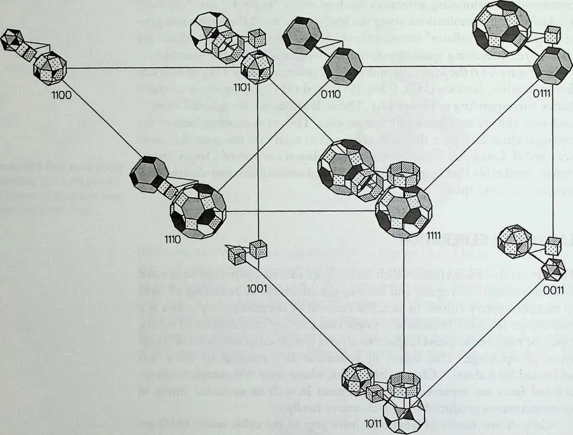
7475Figure 14.7 Basic cells of labyrinths of family (434) in exploded view.
76 each table are suggested by the structures shown in Color Art 12 and 14. Compared with the cubic family (434), these labyrinths are more legitimate four-dimensional labyrinths and can be built in three-dimensional space as ‘‘projections.’’ The cells, as well as the labyrinths composed of these cells, are completely analogous to one another between all the families. These structures are part of a larger table of labyrinths obtained by interconnecting the families. The complete larger table includes all four-dimensional labyrinths, finite as well as infinite, and Euclidean as well as hyperbolic, -dimensional labyrinths (w>4) are similarly included in a larger, more inclusive hypertable.
77 Additional labyrinths for each family are obtained by removing the remaining pairs of complementary-colored faces, namely, blue and orange and yellow and violet. The legitimate labyrinths in these cases are much fewer. Cells of such labyrinths having blue and orange faces removed are shown in Figure 14.11 in a portion of an extended table for four families (333), (433), (533), and (434). In Figure 14.12, cells of labyrinths having yellow and violet faces removed from the structures 1111 of the same families are shown; compare this illustration with Figure 14.6.
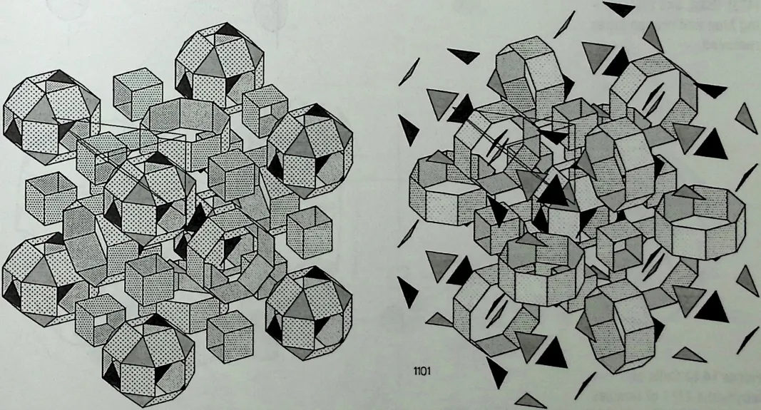
78 Figure 14.8 A detailed view of the labyrinth 1111 in an exploded view (compare with Color Art 9).
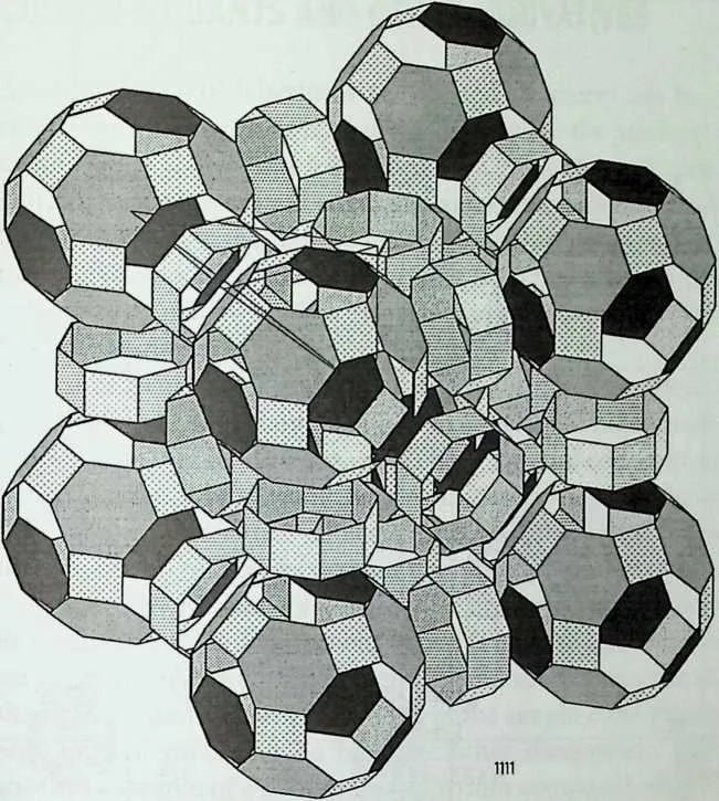
81 Figure 14.10 A detailed view of the labyrinth 1101 in an exploded view (compare with Color Art 9).
82 Figure 14.9 A detailed view of the labyrinth 1011 in an exploded view (compare with Color Art 9).
83 Figure 14.11 Cells of labyrinths of families (333), (433), (533), and (434) having blue and orange faces removed.
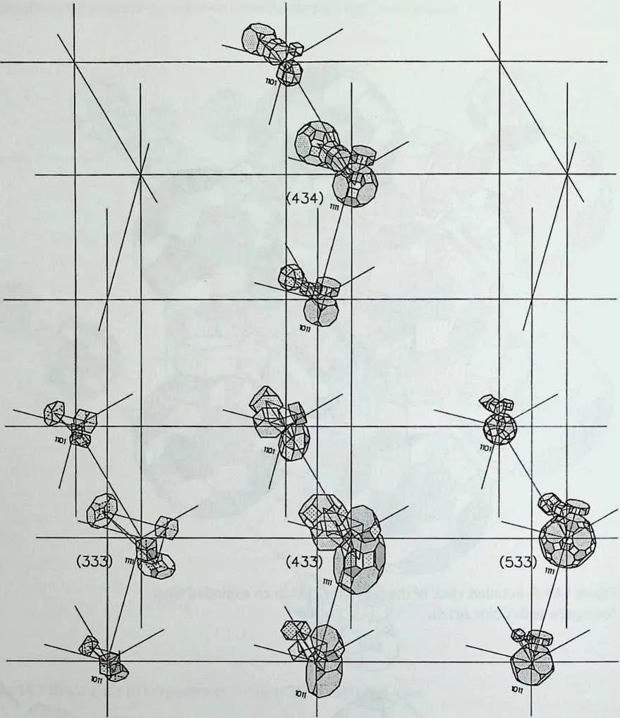
86 Figure 14.12 Cells of labyrinths 1111 of families (333), (433), (533), and (434) having yellow and violet faces removed.
87 CURVED VARIANTS AND OTHER DERIVATIVES
88 A large variety of labyrinths and related structures can be derived from the regular and semi-regular labyrinths described in the previous sections. Nonperiodic space labyrinths related to the new class of quasicrystals, curved labyrinths having curved edges and faces, and periodic as well as nonperiodic labyrinths in non-Euclidean space are interesting examples. Other possibilities include ‘‘curved space’’ labyrinths, which are in non-Euclidean space, as opposed to ‘‘curved surface’’ labyrinths like Pearce’s and Burt’s, which are in Euclidean space.
89 An assortment of examples is shown in the illustrations that follow. Figures 14.13 to 14.20 show examples of a variety of nonperiodic labyrinths projected from higher dimensions. These are embedded in spaces defined by hypercubes and hypercubic lattices and are analogs of the ones derived from the simple cubic lattice shown in the earlier sections. They can be built as three-dimensional projections of the hyperlabyrinths.
90 Figure 14.13 shows a portion of a nonperiodic space labyrinth embedded in an array of six-dimensional cubes. The cells (in their three-dimensional states) are tilted rhombicuboctahedra and the labyrinth is the higher-dimensional analog of the structure 0011 in the simple cubic family of Color Art 9. Similar structures can be built for other dimensions. Figure 14.14 shows another example of a nonperiodic labyrinth composed of tilted truncated octa-hedra and analogous to the cubic labyrinth 0110 of Color Art 9 and Figure 14.7 and belonging to the six-dimensional cubic family. Similarly, the nonpe-
91 Figure 14.13 Portion of the nonperiodic labyrinth having tilted rhombicuboctahedral cells and embedded in a six-cubic lattice (compare with labyrinth 0011 of Color Art 9).
92 Figure 14.14 Portion of the nonperiodic labyrinth having tilted truncated octahedral cells and embedded in a six-cubic lattice (compare with labyrinth 0110 of Color Art 9).
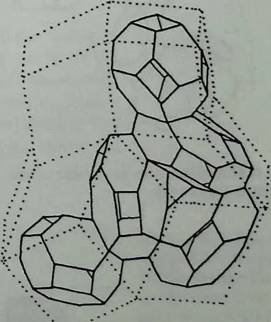
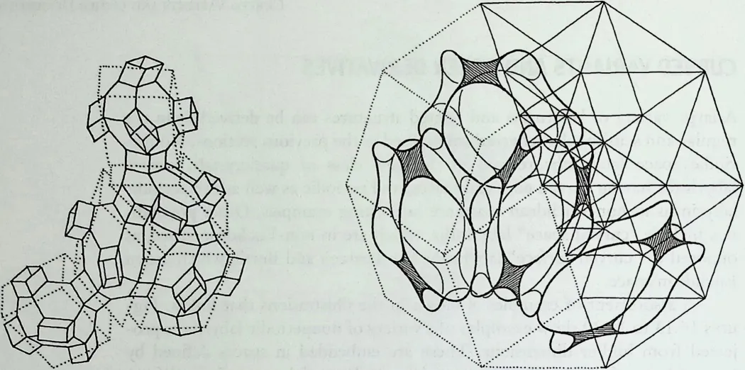
95 Figure 14.16 Portion of the nonperiodic curved surface labyrinth having tilted truncated octahedral cells and embedded in a six-cubic lattice (compare with labyrinth 0110 of Color Art 9).
96 Figure 14.15 Portion of the nonperiodic labyrinth having tilted truncated octahedral cells connected by parallelepipeds and embedded in a six-cubic lattice (compare with labyrinth 1110 of Color Art 9).
97 Figure 14.17 A variant of the nonperiodic curved labyrinth of Figure 14.16.
98 Figure 14.18 Another variant of the nonperiodic curved labyrinth of Figure 14.16.
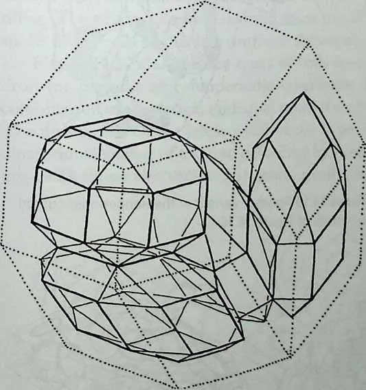
99 Figure 14.19 Schwarz-type cells of dimensions 3,4, and 5 for periodic and nonperiodic labyrinths based on zonohedra.
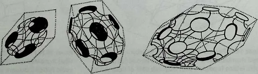
101 Figure 14.20 Alternative geometries for cells of dimensions 3,4, and 5 for labyrinths.
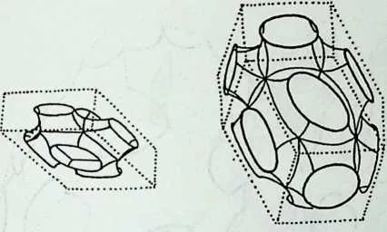
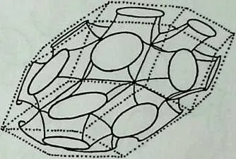
103 riodic labyrinth in Figure 14.15, which is similar to the one in Figure 14.14 but has, in addition, parallelepipeds that connect the truncated octahedra, is a higher-dimensional version of the structure 1110 of Color Art 9.
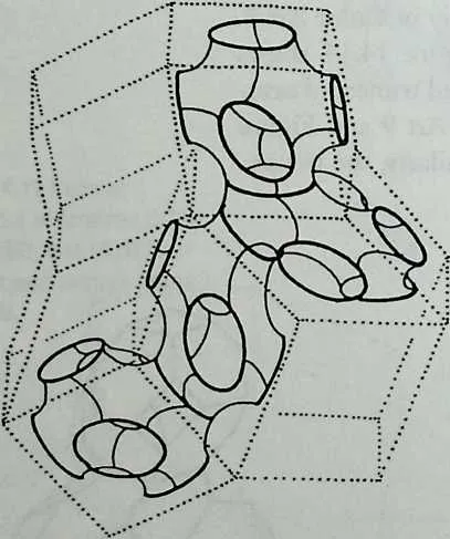
104 Figures 14.16 to 14.18 show curved variants of the hyperlabyrinth of Figure 14.14; the edges are curved inwards or outwards along the plane of the rhombic faces of the hidden hypercubic lattice. These three examples are embedded in the curved variants of the hyper-Schwarz surface. The Schwarz surface is the three-dimensional case first described by Schwarz over 100 years ago,14 and the first example of a hyper-Schwarz surface was developed by Brisson.15 The nonperiodic labyrinth embedded in the hyper-Schwarz surface was first described by Lalvani.6
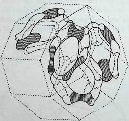
105 Figure 14.19 shows Schwarz-type cells based on zonohedra (outer shells of hypercubes or zonotopes) of dimensions 3,4, and 5. These cells can be used in various combinations to generate periodic and nonperiodic labyrinths. Figure 14.20 shows variations of the cells in Figure 14.19.
106 Figure 14.21 shows a single layer (on the left) from a nonperiodic curved-surface labyrinth based on the upright or tilted prism version of the Penrose tiling. The prisms can be visualized from the illustration in the middle. The space-filling cells of this labyrinth are shown on the right.
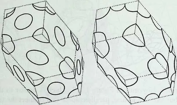
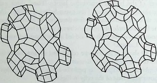
107 Figure 14.22 shows three types of cells based on the rhombic dodecahedron for periodic and nonperiodic labyrinths; the openings can lie on any combination of the vertex, midedge, or midface of the rhombic dodecahedron. The illustration on the left is a cell of the hyper-Neovius surface, the higherdimensional analog of the one described by Neovius over 100 years ago. Figure 14.23 shows two versions of another cell, illustrated with connectors, and
108 Figure 14.21 A single-layered portion of the nonperiodic curved labyrinth corresponding to the prism version of the Penrose tiling. The two small illustrations on the right show cells of multilayered versions of the labyrinth shown on the left
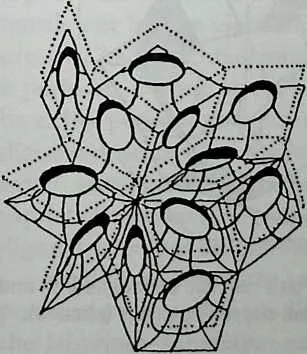
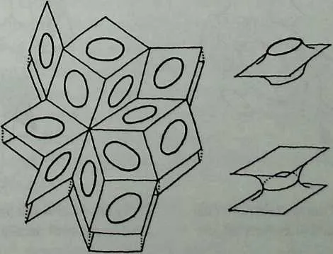
110 Figure 14.22 Cells of labyrinths based on rhombic dodecahedra. The cell on the left is a higherdimensional version of the cells in the labyrinth discovered by Neovius.
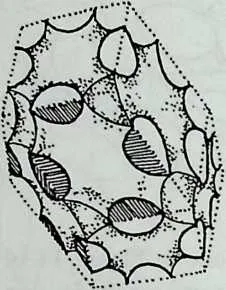
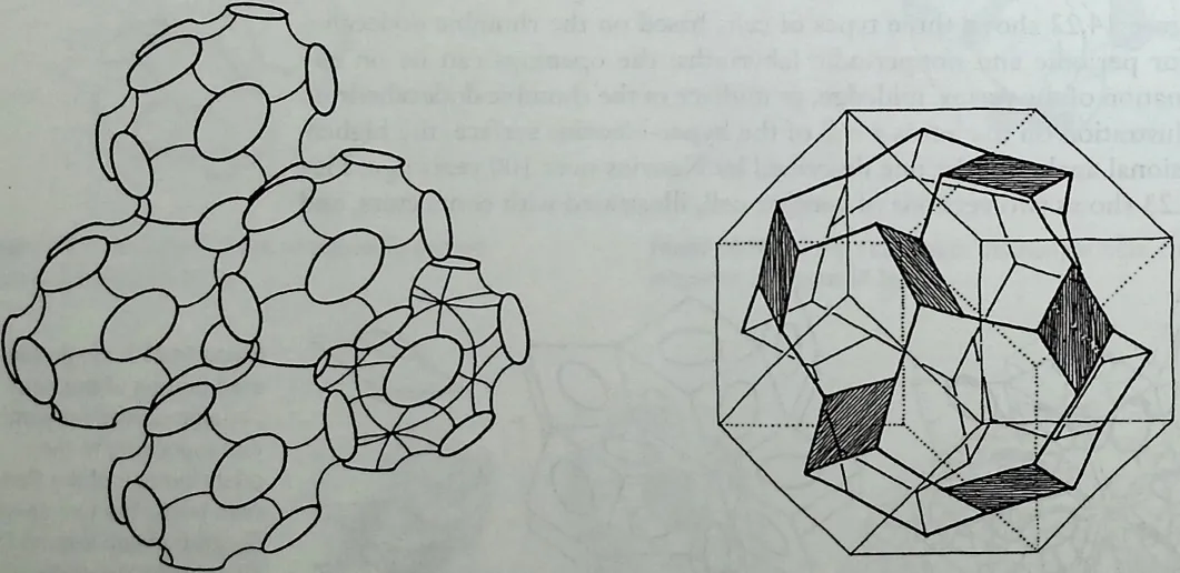
113 Figure 14.25 A cell based on a rhombic dodecahedron and composed of parallelogram-shaped openings (shaded).
114 Figure 14.23 Two variations of a cell of a labyrinth based on the rhombic dodecahedron shown here with connector prisms.
115 Figure 14.24 A periodic array of curved labyrinth composed of cells based on the rhombic dodecahedron.
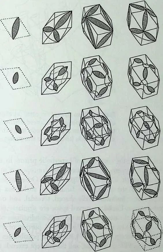
117 Figure 1426 A variety of cells for periodic and nonperiodic labyrinths having digonal openings.
118 also based on the rhombic dodecahedron. Figure 14.24 shows a periodic array of a curved-surface labyrinth composed of cells based on the rhombic dodecahedron. Figure 14.25 shows a cell with parallelogram-shaped openings and also based on the rhombic dodecahedron.
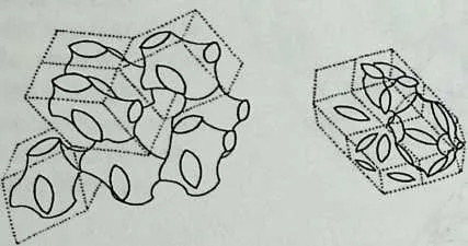
119 Figure 14.26 shows a variety of cells for periodic and nonperiodic labyrinths with digons (two-sided and two-vertexed polygons) as openings. Architecturally, digons (as well as monogons) provide natural shapes of openings for tensile membranes. Frei Otto termed the monogons as ‘‘eyes’’ in his tensile net for the German Pavilion at the Montreal Expo held in 1967. Figure 14.27 shows three examples of labyrinths with digons; the one on the top is periodic, the one on the bottom left is nonperiodic, and the remaining could be either periodic or nonperiodic. Figure 14.28 shows two different cells with digonal openings (on the left), each based on the truncated tetrahedron from which tetrahedral connectors protrude. A periodic array using the cell on the top left is shown alongside. A large variety of other structures composed of digonal openings are similarly possible.
120 Additional labyrinths can be derived from other layered and nonlayered periodic plane and space fillings, and having plane or curved faces, following the labyrinth-generation method described previously. Interesting cases are
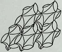
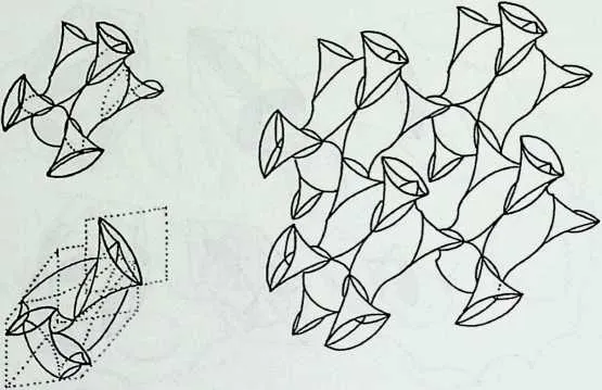
122 Figure 14.27 Portions of periodic and nonperiodic curved labyrinths composed of cells with digonal openings.
123 Figure 14.28 Two types of truncated tetrahedral cells with digonal openings and curved tetrahedral connectors with digonal ends; a periodic labyrinth based on one of the cells (on top left) is also shown.
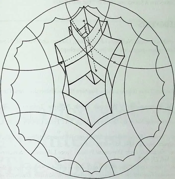
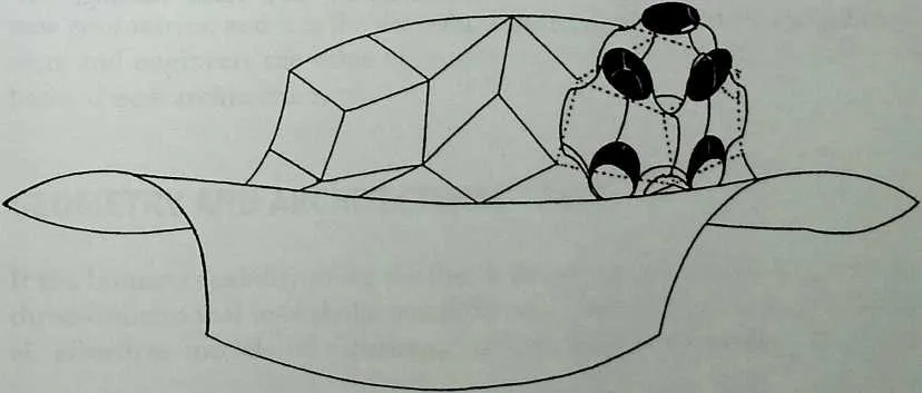
124 the multilayered labyrinths composed of hyperbolic prisms in multilayered versions of Poincare’s hyperbolic disk space. This concept was mentioned by Lalvani9 and one example is shown in Figure 14.29. Other hyperbolic space labyrinths follow and are arranged in families in analogous hypertables. Spherical, ellipsoidal, cylindrical, saddle-shaped, toroidal, and other curved-space labyrinths in non-Euclidean curved space are similarly possible. The spherical and cylindrical cases, based on periodic subdivisions of the sphere and the cylinder, were first mentioned by Burt.10 A portion of a nonperiodic spherical labyrinth is shown in Figure 14.30. Several possibilities are suggested in different parts of the illustration, and the concept extends to all hypergeodesic surfaces developed by the author.16 Interesting cases are fractal labyrinths where the surface of the labyrinth is itself a labyrinth, a process that can be used recursively as well as self-similarly or randomly. One example is shown in Figure 14.31, where a saddle face of a Schwarz-type surface is composed of Schwarz-type modules.
125 Space labyrinths expand the repertoire of spaces and structures available to the architect. Many of the labyrinths presented here, and elsewhere in the author’s work, are mathematically new and await imaginative use as architectural space enclosures and alternatives to building systems. These are presented here to display the exploratory and open-ended nature of morphology, which can continually provide new possibilities for design.
126 Author’s Note
127 Last year (summer of 1995), while curating the Buckminster Fuller Centennial Exhibit, the author received two models of four-dimensional space labyrinths related to the 120-cell from Koji Miyazaki. These models were displayed in the exhibition. In the same exhibition we also displayed the author’s independent work on four-dimensional labyrinths.5,7,8 These hyperlabyrinths, including those derived from the 120-cell, were included in the computer drawing of our higher-dimensional periodic table of space structures, also shown in the exhibition.
128 Figure 1429 One example from a large family of single-, double-, and multilayered hyperbolic labyrinths composed of hyperbolic prisms.
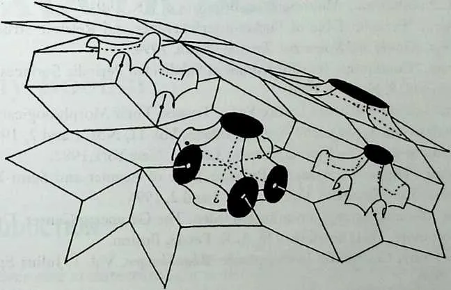
131 Figure 14.30 A portion of a nonperiodic spherical labyrinth; several alternatives are shown.
132 Figure 14.31 A saddle face of a fractal labyrinth where the face is itself a labyrinth surface.
134 ACKNOWLEDGMENTS
135 The author wishes to thank Neil Katz of Skidmore, Owings and Merrill, New York, for all computer-generated drawings in this chapter.
14.2 NOTES
- 1.
- H. S. M. Coxeter, Twelve Geometric Essays, Southern Illinois University Press, Carbondale, 1968.
- 2.
- M. Burt, M. Kleinman, and A. Wachman, Infinite Polyhedra, Technion, Haifa, Israel, 1974.
- 3.
- P. Pearce, Structure in Nature Is a Strategy for Design, MIT Press, Cambridge, MA, 1978.
- 4.
- A. Schoen, ‘‘Infinite Periodic Minimal Surfaces Without Self-Intersections,’’ NASA Technical Note D-5541, May 1970.
- 5.
- H. Lalvani, ‘‘Families of Multi-Directional Periodic Space Labyrinths,’’ Structural Topology, Vol. 21, 1995.
- 6.
- H. Lalvani, ‘‘Non-periodic Space-Fillings of Golden Polyhedra,’’ Proceedings of the First International Conference on Lightweight Structures in Architecture, University of New South Wales, Sydney, 1986.
- 7.
- H. Lalvani, ‘‘Morphological Aspects of Space Structures,’’ in Studies in Space Structures, H. Nooshin, ed., Multi-Science, Brentwood, UK, 1991.
- 8.
- H. Lalvani, ‘‘Periodic Table of Buckminsterfullerenes and Related Structures,’’ Proceedings, Katachi and Symmetry, Tsukuba, Japan, 1994.
- 9.
- H. Lalvani, ‘‘Continuous Transformations of Subdivided Periodic Surfaces,’’ Space Structures, Vol. 5, No. 3/4, 1990.
- 10.
- M. Burt, ‘‘Infinite Polyhedra Lattice Space Trusses: Their Morphological Evolution, Analysis and Application,’’ Space Structures, Vol. 11, Nos. 1 and 2, 1996.
- 11.
- H. Lalvani, Structures on Hyper-Structures, Lalvani, New York, 1982.
- 12.
- H. Lalvani, ‘‘Higher-Dimensional Periodic Table of Regular and Semi-Regular Polytopes,’’ Space Structures, Vol. 11, Nos. 1 and 2, 1996.
- 13.
- Not Knot, 16-minute computer-animated video, The Geometry Center, University of Minnesota, 1991; distributed by A. K. Peters, Boston.
- 14.
- H. A. Schwarz, Gesammelte Mathematische Abhandlungen, Vol. 1, Julius Springer, Berlin, 1890.
- 15.
- D. Brisson, The Hyper-Schwarz-Surface, Brisson, Rehoboth, MA, 1976.
- 16.
- H. Lalvani, ‘‘Hyper-Geodesic Structures, Excerpts from a Visual Catalog,’’ Proceedings of the IASS Conference, Atlanta, 1994.