
16 Are Space Frames Habitable?
2J. Francois Gabriel
16.1 INTRODUCTION
3The preceding chapters offer good arguments in favor of an architecture of polyhedra. The purpose of this chapter is to look at the spaces within, the spaces we would be living in. Are they practical, comfortable, pleasant? Are they varied as well as versatile? Can they be flooded with sunlight? Can they accommodate our furniture, our tools, the equipment on which we depend? In other words, are they as good as our conventional rooms?
4 Most of us live and work in rooms whose shape approximates a cube. Since we spend a lifetime in variations on the cubic theme, we have come to take it for granted that a cube, or a near-cube, is the best shape for a room, in fact the only possible shape for it. We know that generations of other cultures have dwelt successfully in yurts, tepees, and igloos, but few of us would seriously entertain the possibility of living our present lifestyle in one of these. Is it possible to take a rational look at our conventional, ‘‘square’’ dwellings and learn to distinguish between the features that respond to our real needs, practical or emotional, and what is around us thoughtlessly, simply by force of habit?
5 As you can probably see by looking around you from where you are sitting right now, a conventional room is characterized by a horizontal floor and a number of vertical planes: walls, partitions, doors, and windows. There is a logic to that, as gravity makes us stand vertically for balance, and it is easier for the average person to evolve on a horizontal floor than on a slanting one. It also feels good to be surrounded by a modicum of vertical surfaces, for reference or for reassurance. What is not necessary at all is a horizontal ceiling. In fact, the best architecture is more often than not distinguished by shapely roofs or vaults. And what is even more unnecessary is that all the walls meet one another at right angles. We need to orient ourselves easily and to know where we are, and therefore we need an orderly environment, but many orderly environments can, and have been, designed that do not rely on rectangular plans.
6 It is true that we, the people (for whom architecture is made), have a front, a back, and two sides. When life used to be structured around the sun cycles and when religion was unquestioned, to build a room on a square plan was a meaningful, indeed a sacred act. For better or for worse, neither the sun nor religion controls modern life today. The survival of rectangular rooms and buildings is just that: a survival. This is not to say that rectangular spaces are fundamentally wrong. Superb architecture has been generated on a rectangular basis and will undoubtedly continue to be. The points I am trying to make are simply that there are many other avenues to explore in the making of architectural space, and that we deprive ourselves of rewarding experiences when we fail to explore and experiment. Furthermore, many aggregates of polyhedra, in particular, all those discussed in this chapter, do fit in an orthogonal axial system and accept bilateral symmetry as naturally as any buildings conceived on rectangular plans.
7 An important issue to consider when discussing the essential aspects of a room is its height. Ideally, the height of a room should not be considered independently from the shape of its roof. However, most buildings consist of several stories piled up on top of one another and, for reasons of economy, the floor of a room will often be the ceiling of the room underneath. The minimal height is determined by the necessity for even tall individuals to stand up, move about, and wave their arms around without hitting the enclosures. Eight feet in America and 2.5 m in Europe are the standard heights, although some architects are unhappy with such rigid constraints. Frank Lloyd Wright, for instance, ordered a ceiling height of 6 feet, 4 inches in the vestibule of his marvelous design for the famous house Fallingwater.
8 However, there is no upper limit to the height of a room, not only because some of them must contain large objects, but because others might be tall to express an ideal: Have you ever heard anybody complain that the 40-m-high nave of a Gothic cathedral is too high? Probably not. Indeed, the art of architecture does not consist in packing the most in the smallest possible amount of space. It is rather the art of wasting space wisely.
16.2 INSIDE POLYHEDRA
10In this chapter polyhedra will be discussed from an architectural standpoint, an important part of which concerns, naturally, their habitability. There are so many polyhedra and combinations of polyhedra with architectural possibilities that a selection had to be made for our case study. Only two polyhedra were retained: the tetrahedron and the octahedron. In fact, a further restriction proved necessary: Our two polyhedra will be examined with their position remaining constant with regard to the ground. What we learn from these two will increase our understanding of any other polyhedral combination.
11 There are several reasons for selecting the tetrahedron and the octahedron. One is that they are the simplest of all polyhedra. Another is that they can together organize space, something that neither one can do individually. If a tetrahedron is placed on each face of an octahedron, clones of the octahedron will fit perfectly against the exposed faces of the tetrahedra. The process can be repeated indefinitely, producing what is called an infinite structure (Figure 16.1).
12 What may appear to be a digression will be useful here. The names given to polyhedra indicate the number of their faces. Thus we know from their names that a tetrahedron has four faces and an octahedron has eight. However, if all the faces were removed and only their edges remained, the three-dimensional configuration would be essentially the same. Only our perception changes. What we understood as an aggregate of solids is now a space lattice.
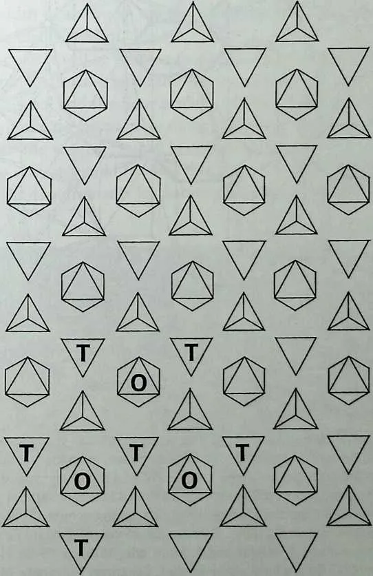
14 Figure 16.1 Octahedra and tetrahedra can organize space without gaps or overlap when the faces of the octahedra are in contact with the faces of the tetrahedra. In this top view, polyhedra are pulled apart to show that an octahedron (0) is surrounded by six tetrahedra, three of them straight side up and the others (T) upside down.
15 Both are infinite structures; in fact, they are the same. (The reader who is not familiar with this space lattice will probably experience difficulties at this point. Alan Holden would recommend the making of a model. As he says: ‘‘The best way to learn about these objects is to make them, next best to handle them.’’11 would recommend the use of wooden toothpicks, the round sort that are tapered at both ends. Assemble them with a good glue and keep in mind that accuracy is important.)
16 We are interested in the spaces found within our tetrahedron-octahedron space lattice. They are our ‘‘rooms.’’ What shapes are they? The answer depends on the position of the space lattice with regard to the ground. When the struts found in horizontal planes meet at right angles, the space lattice is called a two-way space frame, and all the rooms are in the shape of cubes.2 When the horizontal struts form triangles, the space lattice is called a three-way space frame, and all the rooms are in the shape of hexagonal prisms (Figure 16.2).
17 Most people are already familiar with the cube, and the object of this book
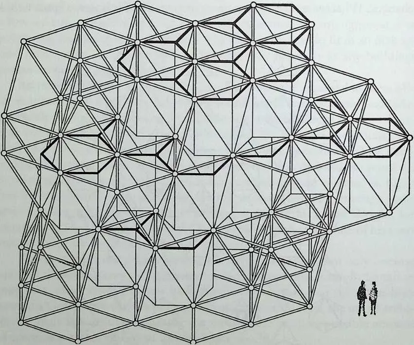
19 Figure 16.2 A three-story aggregate of octahedra and tetrahedra with faces deleted. Only edges remain, in the form of struts, to form a space lattice, or space frame. Because the horizontal struts are arranged in triangles, this is called a three-way space frame. A honeycomb pattern of hexagonal rooms is obtained by the addition of vertical planes against the diagonals, which are the struts connecting one floor to the next. (Source: J. F. Gabriel, ‘‘Three-Dimensional Suburbs,’’ Proceedings of the IASS World Congress on Space Enclosures, P. Fazio, G. Haider, and A. Biron, eds., 1976, pp. 89–99, Fig. 3. Reprinted with permission of the Centre for Building Studies, Concordia University, Montreal.)
20 is to present other, lesser known spaces, waiting for discovery inside polyhedra. We will therefore abandon the two-way space frame and its cubic spaces to focus our attention exclusively on the three-way space frame. How exactly are the hexagonal spaces seen in Figure 16.2 obtained? Simply by applying a vertical surface (wall panel or cladding) to the struts that connect one floor to the next. These struts are called diagonals, and the floor structures they connect are referred to as chords. Spatially, we have gone from an aggregate of octahedra and tetrahedra to a honeycomb pattern: Each octahedron has increased in size and volume by absorbing, as it were, a third of the volume of six adjacent tetrahedra.
21 The natural place for doorways is where diagonals form ‘‘A-frames,’’ that is, where three diagonals are joined by their upper extremities. Three doorways can be found in each hexagonal room, in alternate comers, and each doorway gives access to two other rooms (Figures 16.2 and 16.3).
22 For my studies I have usually adopted a regular octahedron with an edge length of 4 m. A standard octahedral frame of that size would provide a rather small but adequate room within. The corresponding floor-to-floor height will be 3,266 m. Headroom will be ample regardless of the depth of the floor structure itself, which depends on many factors such as building materials, building program, size and shape of the overall structure, climate, and so forth. The width of the room, measured between parallel walls, is 4 m and, measured diagonally, 4.62 m.
23 In many cases it will be possible to give hexagonal rooms what might be a more pleasant height-to-width ratio by decreasing their height. The angle between a diagonal and the floor plane is 54° 44' 8". Reducing this angle to 45° might improve the proportions of the space within and have the advantage of squaring off the vertical faces of hexagonal prisms.
24 With this said, it should be clear that a space frame of appropriate depth meets the basic requirements for habitability. Horizontal floors, headroom,
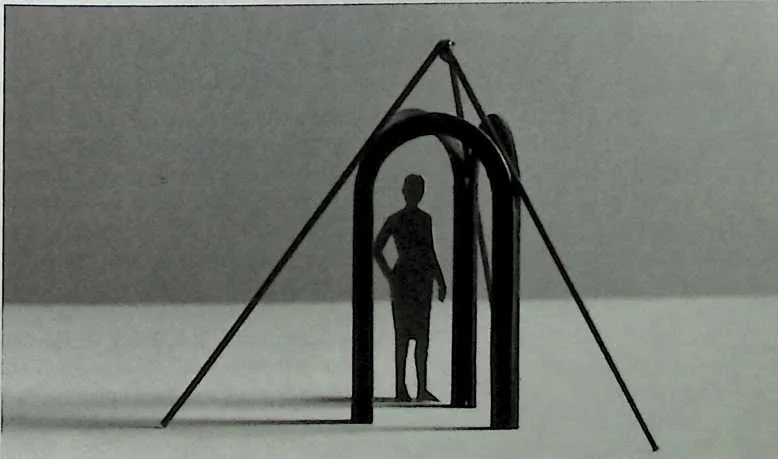
26 Figure 16.3 Three diagonals meeting overhead provide the space for doorways. This occurs in alternate corners of each hexagonal room, that is, three times per room. Thus each room can have access to six others.
27 vertical walls, accessibility are necessary in buildings, but are these conditions enough? Can a space frame accommodate vertical shafts, or wells, of varied cross section wherever they are needed? We will address the problem of fitting stairs, elevators, and flues, without which buildings are not viable, in the next section of this chapter.
28 At this point, a word of clarification is in order. This chapter is written by an architect and is about architecture, not structure. Of course, structural considerations should never be ignored altogether, especially since they are an important argument for the increased use of space frames, but here they are looked at in their broadest general aspects. Space frames are attractive to me, as an architect, because their geometry makes them essentially indeformable. They are lightweight structural frameworks made versatile by their structural redundancy. They lend themselves to the design of large buildings, the form of which could not be obtained otherwise, and they can provide the answer to many difficult urban problems. They are modular and therefore orderly. They can be produced industrially, and they can be designed for reuse.
16.3
30CUMBERSOME CHORDS
31 Unlike the conventional post-and-beam system, which is three directional, our space lattice is a six-directional system. Seen from above, a multistory, three-way space frame presents an intricate mesh. The introduction of vertical shafts would be very difficult, for it would require the elimination of considerable portions of the space frame. It would also lead to a breakdown of the system because chords and diagonals would not be lined up (Figure 16.4).
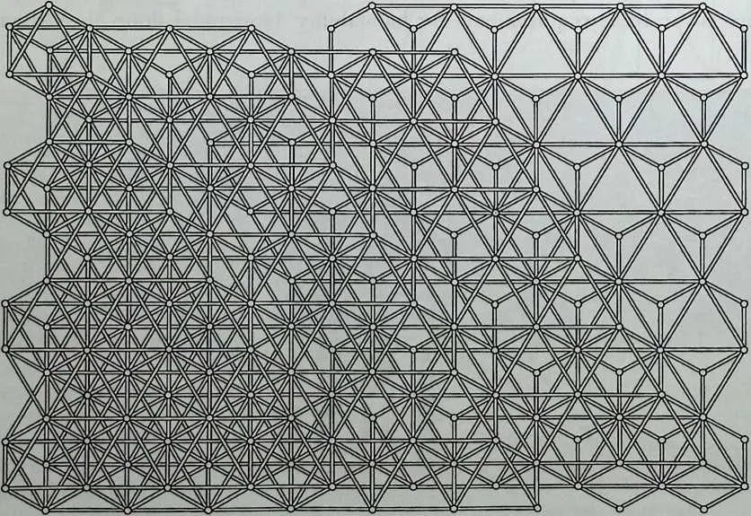
33 Figure 16.4 Top view of a multilayer, three-way space frame. Although the chords are all made of the same triangular pattern, they shift with the diagonals from floor to floor with the end result a complicated, obtrusive mesh. The insertion of vertical shafts is difficult. Many structural members would have to be removed, opening up irregular spaces that do not coincide with the vertical surfaces of shafts.
34 With the reader’s permission, I would like to make a recommendation. Visualization of the six-directional space lattice is not easy to achieve for one who is not thoroughly familiar with the morphology of noncubic configurations. It requires patience. To avoid fatigue and discouragement, I would suggest that the reader go over the drawings with color pencils and tracing paper until the spatial relationships described in this chapter become clear and familiar.
35 The next drawing represents the same configuration as Figure 16.4, also seen from above, but with the chords deleted. Only diagonals are shown, up
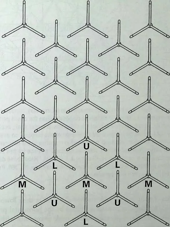
37 Figure 16.5 Top view of the same configuration as in Figure 16.4, with the chords deleted. Diagonals are shown up to two-thirds of their height and attached to a joint at their lower extremity. Instead of identifying consecutive floors with numbers such as 1,2, and 3,1 prefer to use the letters L, M, and U, referring to lower, median, and upper levels. One sees that the L-M-U sequence is complete and will repeat itself again and again as the structure goes up. The honeycomb pattern formed by the diagonals on every floor can be clearly seen. The triangular pattern resulting from the horizontal projection of the diagonals indicates that vertical shafts could be found anywhere, as long as the chords are not allowed to interfere. Chords can indeed be modified in order to superimpose exactly with the diagonals. As long as the floor joints continue to be connected by a triangular grid, no weakening of the structure will ensue. (Source: J. F. Gabriel, ‘‘Three-Dimensional Suburbs,’’ Proceedings of the IASS World Congress on Space Enclosures, P. Fazio, R Haider, and G. Biron, eds., 1976, pp. 89–99, Fig. 11. Reprinted with permission of the Centre for Building Studies, Concordia University, Montreal.)
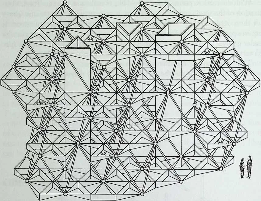
4041Figure 16.6 Vertical shafts can be inserted anywhere in a three-way, multistory space frame without interfering with either chords or diagonals when the chord pattern is made to conform with the horizontal projection of the diagonals. A larger shaft, such as is shown on the right, would only require the elimination of one diagonal on every third story. The profile of the chord elements is modified in response to the different loading conditions that affect inhabited space frames, as opposed to space frames simply used to cover or enclose large, open spaces. (Source: J. F. Gabriel, ‘‘Habitabilite des structures tridimensionelles a I'echelle urbaine,’’ Techniques et Architecture, No. 309, Paris, 1976, pp. 110–112, Fig. 6. Reprinted with permission.).
42 to two-thirds of their height, and attached to a joint at their lower extremity (Figure 16.5). A triangular pattern is formed by the horizontal projection of the diagonals. If the chord pattern could be made to conform with that of the diagonals, triangular wells could be introduced anywhere in a three-way space frame and this without interference from either chord members or diagonals. It so happens that this can be achieved quite easily: Chords -will superimpose precisely 'with the diagonals when they are rotated 30° in their own plane, which is, of course, the horizontal plane (Figure 16.6).
43 Triangular shafts obtained from this simple operation measure 2.31 m on the side. A large elevator could fit comfortably in a shaft of this size, and any number of shafts can be created anywhere, either in bundles or scattered throughout the structure. It should be underlined that triangular elevator cabins are more efficient than rectangular cabins, for they fill up and empty faster.
44 For stairs, larger wells can be made by opening up several triangular shafts onto each other. This requires the elimination of some diagonals, but remaining chords and diagonals will always coincide with the ‘‘walls’’ of the shafts, whether their shape is a triangle, a hexagon, or a parallelogram.
45 We are interested in lived-in space frames and polyhedra, where loading conditions are quite different from those in single-or double-layer space frames used to cover large, column-free spaces, such as sports arenas or convention centers. Our new floor structure reflects this difference in a new, tapered profile. The floor structure itself is fully triangulated in all directions. Its configuration is of the space frame type, and the elimination of certain portions of it would not compromise its geometric rigidity.
46 The tapering of the floor structural elements, added to the minor modification performed on the chords, open up a number of architectural and structural possibilities, some of which are described in the following sections.
16.4 THE HEXMOD: ITS MORPHOLOGY
48This chapter began with a description of the space frame considered as an aggregate of octahedra and tetrahedra. These shapes are also called geometric solids and, for that reason, they are unfortunately perceived not as spaces but as solid masses. Because we are interested in them as voids, it will be useful to
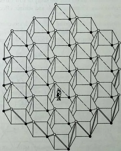
50 Figure 16.7 Originally, the diagonals represented the edges of octahedra and tetrahedra, but that reading has been replaced by a new one. When vertical planes are placed along the diagonals, a honeycomb pattern is created. Doorways find their place where diagonals meet on an upper joint. Each doorway gives access to two other hexagonal rooms. Because there are three doorways in each room, each room has access to the six rooms that surround it. (Source: J. E Gabriel, "Space Frames: The Space Within-A Guided Tour,’’ International Journal of Space Structures, Vol. 1, No. 1, 1985, pp. 3–12, Fig. 3. Reprinted with permission of Elsevier Science Ltd, The Boulevard, Langford Lane, Kidlington 0X5 1GB, UK.)
51 think of a space frame as an infinite structure of hollow ‘‘geometric solids.’’ I have already dispelled the myth that the spaces within must of necessity be in the shape of either a tetrahedron or an octahedron. This was done by showing that a space frame can form a honeycomb (Figure 16.7).
52 Now, a honeycomb may satisfy the crudest needs for shelter, but it can hardly be expected that a honeycomb will have the malleability required by the complexity and the variety of our building programs. All the rooms cannot be the same shape and the same size.3
53 Is it possible to ‘‘open up,’’ as it were, the honeycomb pattern and not lose the structural strength of the space frame, which is one of the main reasons for our interest in them? One of the major differences between the post-and-beam structural system and the three-way space frame is this: Whereas there can only be one vertical column in one place in the former, there are normally three diagonals in the latter. This may be redundant under certain conditions, but it must be remembered that diagonals do more than carry loads; they ensure the rigidity of the structural framework. It is conceptually possible to eliminate in a systematic way some of the diagonals from the framework without compromising its geometric rigidity.
54 Once again, this chapter is concerned with concepts and speculation, and one should, of course, never forget that the safety of structures depends precisely on their redundancy. Changing winds and seismic effects create load reversals that must be met somehow.
55 What if we assumed that the standard cell of our honeycomb is a building block? It is, after all, basically an octahedron, which is indeformable. From the antiprism that it was, it has been transformed into a hollow, hexagonal prism.
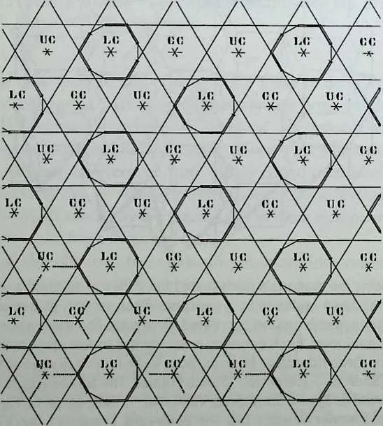
57 Figure 16.8 The framework of a hexagonal room can be considered as a building block called a hexmod. Instead of remaining tightly packed, the building blocks are here separated by a distance equal to their width, that is, 4 m. This redistribution lets architectural space flow around freestanding hex-mods. The lower left area of the drawing shows where the eliminated diagonals used to be. The new, open pattern uses only one-half of the original number of diagonals.
58 However, it is still a geometrically rigid frame. We call it a hexmod because it is a module and it has a hexagonal plan. What if we distributed hexmods on a horizontal base, 4 m apart (which is also their width) and on a repeating pattern of hexagons and triangles? The spatial transformation is radical and can be appreciated by imagining ourselves standing between ‘‘building blocks’’ and looking around: We can see between building blocks and our line of vision is uninterrupted in six directions (Figure 16.8). An axonometric drawing of one story will help us to better understand the relationship between all the elements of the structure. Three joints of the upper floor, out of four, are still supported, but instead of each joint being supported by three diagonals, it is now supported by two. This means that half the diagonals can be eliminated. A hexmod sits on three others, situated on the floor below, and shares one of its three lower joints with each. Likewise, a hexmod shares its three upper joints with three hexmods situated on the floor above, helping to support them (Figure 16.9).
59 A hexmod consists of six diagonals connecting two very similar hexagonal frames, one forming the floor of the hexmod and the other forming its roof. These frames are called, respectively, the lower cap and the upper cap of the hex-mod, or LC and UC (Figure 16.10).

61 Figure 16.9 The six diagonals of a hexmod connect three lower joints to three upper joints. In a regular, multilayer space frame, a joint would receive six diagonals, three underneath and three above the joint In the new pattern, a joint receives only two diagonals from above and two from below. For greater visual clarity, the tops of the hexmods are deleted on both upper and lower floors. (Source: J. F. Gabriel and J. Mandel, ‘‘A Space Frame Building System for Housing,’’ Proceedings of the Third International Conference on Space Structures, H. Nooshin, ed., Elsevier, London, 1984, p. 1054, Fig. 5. Reprinted with permission of Chapman and Hall, Cheriton House, North Way, Andover, HANTS, SP10 5BE, UK.)
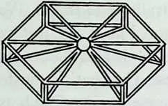
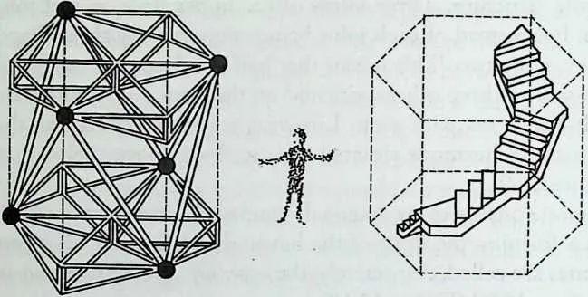
64 Figure 16.10 A building system based on the hexmod building block requires an inventory of only two components, the hexmod itself and a hexagonal subassembly, called a complementary cap, that is used to connect hexmods with one another. It is called CC, while the upper and lower caps of the hexmod itself are called DC and LC, respectively. The drawing also shows a stairs component. Although not structural, it is an indispensable element of the building system. It fits within a hexmod and does not require the elimination of any diagonals to be functional. (Source: J. F. Gabriel and J. Mandel, ‘‘The Application of Lightweight Modular Structures to Housing,’’ in Housing, the Impact of Economy and Technology, 0. Ural and R. Krapfenbauer, eds., Pergamon Press, 1981, p. 65, Fig. 1.)
65 Another subassembly contributes to the building system. It is also hexagonal and it is called the complementary cap, or CC. It is an essential component for two reasons. It makes floors continuous by filling the gaps between hex-mods. Its three-dimensional design makes it a geometrically rigid unit and, theoretically at least, this renders a number of diagonals structurally redundant. In the original space frame, six diagonals would have met at the joint that is now at the center of a CC. Because of its geometrically rigid shape, the CC should no longer require support at its center. Presumably, the six diagonals that would have met at the center of the CC—three above and three below—can be deleted. Spanning, vertical load transfer, and resistance to lateral stresses can all be theoretically handled by hexmods and CCs.
66 Whereas these two modules constitute the complete inventory of parts, another component must be added to make the building system complete and viable: a stair module. The proposed helicoidal design fits comfortably within a hexmod and can also be used between hexmods. The clear space between handrails is 1 m or even wider.
67 Returning to Figure 16.8 for a moment, we see that LCs and UCs form two out of three hexagons of the floor structure, on this and any other story.
68 The hexagons marked CC, for complementary cap, complete the pattern of hexagons of the floor structure. Each CC is connected with six caps by its corners; three of them are UCs and the others are LCs. This relationship can also be seen in Figure 16.13.
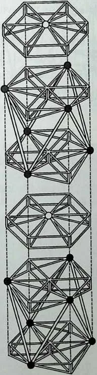
69 To finish our description of the spatial relationships that exist between hexmods and between hexmods and CCs, one more remark will be useful: In a vertical sequence, a hexmod is always found on an intermediate floor, between two superimposed CCs (Figure 16.11). The next drawing shows the structural connection between subassemblies: Six diagonals carrying a CC belong to three distinct hexmods. Likewise, six diagonals belonging to another set of three hexmods carry the hexmod directly above a CC (Figure 16.12).
70 The trade-off caused by the eventual elimination of half of the diagonals would be total structural interdependency between the hexmod and CC com-
71 Figure 16.11 Hexmods and CCs always alternate in a vertical sequence of several stories. The joint at the center of the CC is not connected with diagonals, as it would be in the original space frame. (Source: J. F. Gabriel and J. Mandel, ‘‘The Application of Lightweight Modular Structures to Housing,’’ in Housing, the Impact of Economy and Technology, 0. Ural and R. Krapfenbauer, eds., Perg- amon Press, 1981, pp. 64–65, Fig. 2© J. F. Gabriel and J. Mandel.).
72 Figure 16.12 This figure shows the same relationship as Figure 16.11 does, but here all the diagonals are shown. A hexmod is carried by three hexmods underneath. Vertical planes placed against the diagonals make the location of these hexmods explicit A CC is also carried by three hexmods.
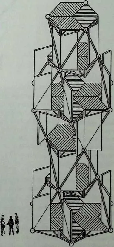
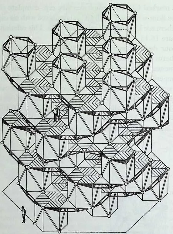
75 Figure 16.13 A six-story structure may be too ambitious for a building system that relies on structural members, presumably made of steel, the cross sections of which should be as small as possible. The intent of this drawing is merely to confirm the three-dimensional relationships described in the text Although not representing a finished building, the drawing gives an idea of how such a building might appear. Except for the six hexmods on the upper floor, all the others play a structural part in a configuration like this. (Source: J. F. Gabriel, ‘‘Dwelling in Space Structures,’’ in Studies in Space Structures, H. Nooshin, ed., Multi-Science Publishing, Brentwood, UK, 1991, pp. 69–86, Fig. 7. Reprinted with permission.)
7778ponents. Structural interdependency exists to a point in any building technology, and it cannot be regarded as a serious hindrance to design. As with any language, be it verbal or visual, the discipline of a syntax is only an obstacle to expression when it is not mastered. Without a language, complete with rules and limitations, nothing can be expressed, nothing can be communicated. However, there is no single building technology capable of satisfying all the building requirements of our time. Like all systems, the hexmod has its limitations, but it also has its special merits (Figure 16.13).
79If I described in some detail the interrelationships of all the components, it is because they are essential to an understanding of the structural concept as a whole and to an overview of the architectural horizons it opens. A good part of the rest of this chapter will discuss formal variations on the same theme. We will see designs that the hexmod system cannot handle alone but which can be built with other combinations of the same parts.
80 THE HEXMOD: A BUILDING SYSTEM
81 My fascination with space frames stems in part from the multiplicity of stable configurations that can be obtained from the six-directional space lattice. For this reason, it would be of questionable interest to choose a space frame as the matrix for a low, ground-hugging building. On the other hand, fire safety imposes limitations on the height of a structure relying on thin structural members. Hexmods are adequate for buildings three or four stories high.4
82 It is obvious that stairs are vital in walk-up buildings. The hexmod system can accept a great number of different stair designs. One approach is to confine stairs to an enclosed vertical shaft, and certain building codes do indeed require such a solution for emergencies. This conventional design can be accommodated within a hexmod framework because, as we have seen, vertical shafts of varied size and shape can be inserted anywhere (Figure 16.6).
83 Instead of being confined into a sort of rigid, vertical ‘‘tube,’’ the stair modules could overlap and, in doing so, engage the user in a spatial experience that calls to mind Le Corbusier’s architectural promenade. Perhaps this point should be elaborated. It is true that the shortest distance between two points is a straight line, but it is not necessarily true that a straight path will always feel shorter. A boring walk will seem longer to the user, or at least to the user who is aware of his/her environment, whereas an interesting or pleasant walk will seem shorter. An architect must know how to make the distinction. By
84 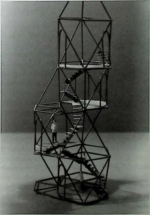 Figure 16.14 In a three-way, multilayer space frame, octahedra overlap by one-third, as
do the bee cells of a honeycomb. A modular stair, 1 m wide, can fit in a hex-mod (see Figure
16.10). Hexmods containing stairs must be rotated by 120° when they are superimposed, in order
to achieve these objectives: No diagonals need be removed to create headroom in the stairs.
Landings will consist of two-thirds of the floor of a hexmod. Two doorways on every landing will
give access to the rest of the floor. The configuration of hexmods will approximate a helix,
completing a revolution in three stories. (Source: J. F. Gabriel, La Poutre-etoile,’’
Techniques et Architecture, No. 320, Paris, 1978, pp. 70–71. Reprinted with permission. J. F.
Gabriel, ‘‘Dwelling in Space Structures,’’ in Studies in Space Structures, H. Nooshin, ed.,
Multi-Science Publishing, Brentwood, UK, 1991, pp. 69–86, Fig. 22. Reprinted with
permission.)
Figure 16.14 In a three-way, multilayer space frame, octahedra overlap by one-third, as
do the bee cells of a honeycomb. A modular stair, 1 m wide, can fit in a hex-mod (see Figure
16.10). Hexmods containing stairs must be rotated by 120° when they are superimposed, in order
to achieve these objectives: No diagonals need be removed to create headroom in the stairs.
Landings will consist of two-thirds of the floor of a hexmod. Two doorways on every landing will
give access to the rest of the floor. The configuration of hexmods will approximate a helix,
completing a revolution in three stories. (Source: J. F. Gabriel, La Poutre-etoile,’’
Techniques et Architecture, No. 320, Paris, 1978, pp. 70–71. Reprinted with permission. J. F.
Gabriel, ‘‘Dwelling in Space Structures,’’ in Studies in Space Structures, H. Nooshin, ed.,
Multi-Science Publishing, Brentwood, UK, 1991, pp. 69–86, Fig. 22. Reprinted with
permission.)
85 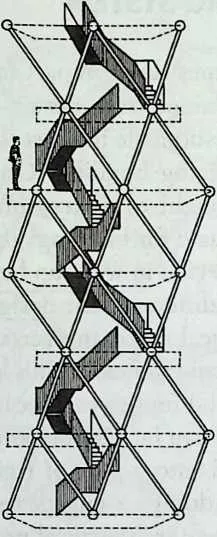
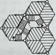 Figure 16.15 Plan and elevation of the configuration shown in Figure 16.14.
(Source: J. F. Gabriel, ‘‘Dwelling in Space Structures,’’ in Studies in Space Structures, H.
Nooshin, ed., Multi-Science Publishing, Brentwood, UK, 1991, pp. 69–86, Fig. 20. Reprinted with
permission.)
Figure 16.15 Plan and elevation of the configuration shown in Figure 16.14.
(Source: J. F. Gabriel, ‘‘Dwelling in Space Structures,’’ in Studies in Space Structures, H.
Nooshin, ed., Multi-Science Publishing, Brentwood, UK, 1991, pp. 69–86, Fig. 20. Reprinted with
permission.)
86 engaging users in the stories through which they travel, stairs can enhance the quality of life in certain types of buildings.
87 Interesting designs like these can make use of modular stairs that actually fit within hexmods (Figure 16.10). These can even be inserted in a ‘‘saturated’’ space frame, which is one from which no diagonal has been deleted (Figures 16.14 and 16.15). The same helicoidal module can be oriented in one of three directions. If the modules were rotated 120° from floor to floor, they would generate a helicoidal path that would repeat every three stories. Another pattern can be obtained from assembling the same stair modules in a straight line parallel to one set of diagonals (Figure 16.16).
88 For the helicoidal module to fit inside a hexmod, the width of the stairs can barely exceed 1 m. Domestic programs do not normally require wider stairs than that. Wherever wider stairs are needed, however, they too can be accommodated within the hexmod system. Of course, more space must be cleared for them. Stairs as wide as 2 m, or even 4 m—the equivalent of a hex-mod’s width—should satisfy the circulation requirements of any building (Figure 16.17). The drawings actually suggest several design solutions for varying widths, all of them fitting in a vertical shaft 2 or 4 m wide.
89 This brief survey of possible stair designs is not exhaustive, and the hex-
90 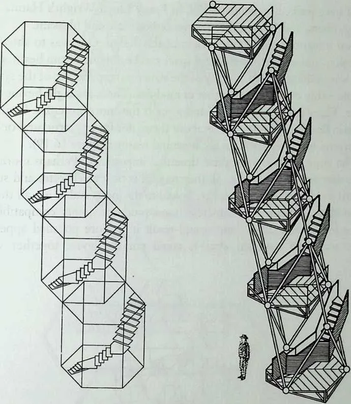 Figure 16.16 Instead of being rotated on every floor, the orientation of the stairs can
remain constant Instead of a helix, the new pattern will move in the direction of one set of
diagonals. (Source: J. E Gabriel, ‘‘Dwelling in Space Structures,’’ in Studies in Space Structures,
H. Nooshin, ed., Multi-Science Publishing, Brentwood, UK, 1991, pp. 69–86, Fig. 19. Reprinted
with permission.)
Figure 16.16 Instead of being rotated on every floor, the orientation of the stairs can
remain constant Instead of a helix, the new pattern will move in the direction of one set of
diagonals. (Source: J. E Gabriel, ‘‘Dwelling in Space Structures,’’ in Studies in Space Structures,
H. Nooshin, ed., Multi-Science Publishing, Brentwood, UK, 1991, pp. 69–86, Fig. 19. Reprinted
with permission.)
91 mod system can accept many others. Indeed, this structural framework is not restrictive at all.
92 To illustrate the architectural possibilities of the hexmod building system, I would like to present a design for a small building: a two-bedroom residence (Figure 16.18). The main rooms are all on the second level. A central living space with openings in three directions is extended by two outdoor decks. The kitchen and dining zone is at one end of the living space, the sitting area at the other end. There is a private study and, opposite to it, the two bedrooms, sharing a bathroom. The study and the bedrooms, which are in greater need of privacy, occupy three of the hexmods on the main floor. The fourth hex-mod houses the stairs. As for the single hexmod on the roof, it does nothing more than enhance the dynamics of the space. Its lower cap has been removed, and the opening in the plane of the roof stretches the verticality of the enclosed space for the viewer. As one prepares to ascend the stairs and looks up, one is silently invited to move upwards.
93 Entering the house is done under the shelter of the main floor, which is cantilevered. One end
of the hall can be closed off to serve as a utility room, a workshop, a garden room, a powder
room, or storage. Access to the main floor is gained by a stair of a design we have not
yet seen. The steps form a 30° angle with the stringers, to be consistent with the
hexagonal/triangular
plan. I have walked on similar stairs, in Frank Lloyd Wright’s Hanna House among others, and I
found the experience both safe and pleasant.
94 Two intentions were at the origin of the design. One was to show that a convenient and attractive residential space can be obtained from hexmods. The other was to demonstrate as many of the structural capabilities of the system as possible, using the smallest number of modules. There are eight hexmods altogether. Three rest on the ground and support the entire structure. Four are on the main floor, and the last one is above them, not for any structural or practical purpose but for a poetic or architectural reason (Figure 16.19).
95 The large joints express their structural importance. Perhaps more to the point, they are easy to make. All they require is bent steel plates and straightforward welding. The diagonals are bolted to the joints and so are all the struts of the floor structure. Commercial mass-produced joints compatible with square tubes are available and would result in a more polished appearance. Either way, two unskilled workers could put the house together without
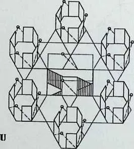
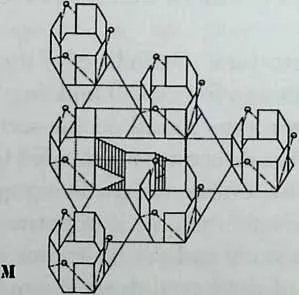
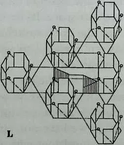
98 Figure 16.17 Although they demand much more space, stairs up to 4 m in width only require the deletion of a few diagonals on every floor. Nowhere must a complete hexmod be removed to accommodate the stairs. (Source: J. F. Gabriel, ‘‘Dwelling in Space Structures,’’ in Studies in Space Structures, H. Nooshin, ed., Multi-Science Publishing, Brentwood, UK, 1991, pp. 69–86, Fig. 23. Reprinted with permission.).
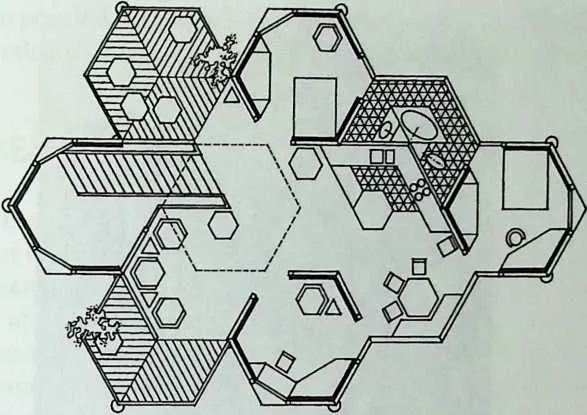
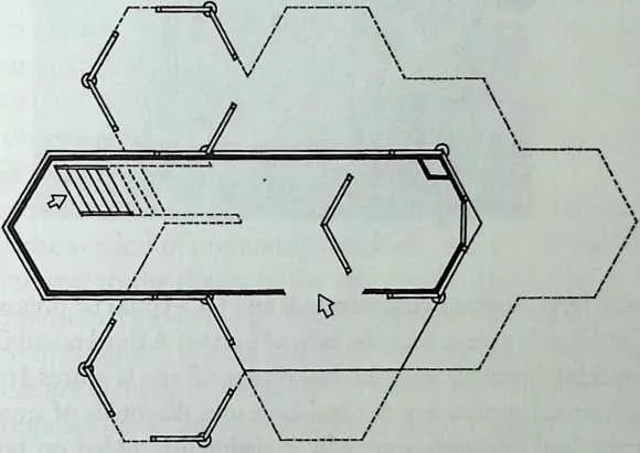
100 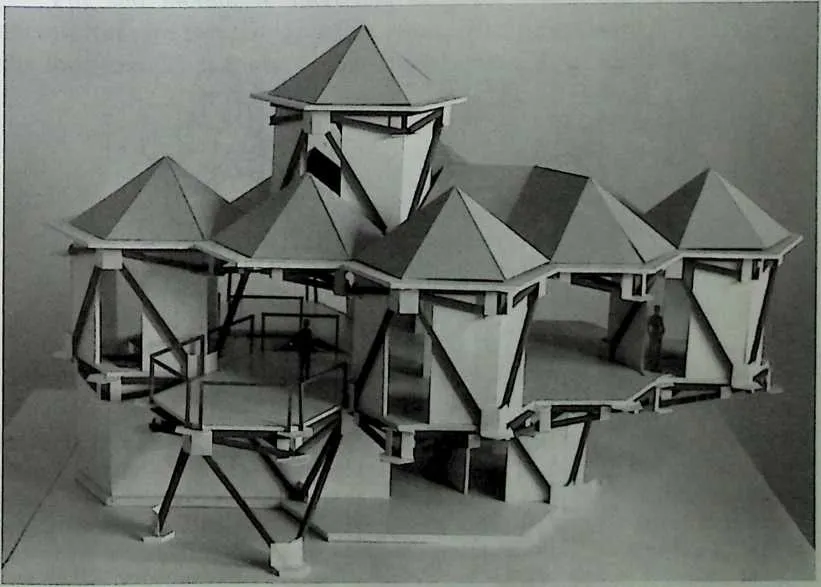 Figure 16.18 Plans of the ground level and of the main floor of a two-bedroom house.
Three hex-mods are in contact with the ground and carry the entire structure. (Source: J. F.
Gabriel and J. A. Mandel, ‘‘A Space Frame Building System for Housing,’’ Proceedings of the
Third International Conference on Space Structures, H. Nooshin, ed., Elsevier, London, 1984, p.
1052, Fig. 8. Reprinted with permission of Chapman and Hall, Cheriton House, North Way,
Andover, HANTS, AP10 5BE, UK.)
Figure 16.18 Plans of the ground level and of the main floor of a two-bedroom house.
Three hex-mods are in contact with the ground and carry the entire structure. (Source: J. F.
Gabriel and J. A. Mandel, ‘‘A Space Frame Building System for Housing,’’ Proceedings of the
Third International Conference on Space Structures, H. Nooshin, ed., Elsevier, London, 1984, p.
1052, Fig. 8. Reprinted with permission of Chapman and Hall, Cheriton House, North Way,
Andover, HANTS, AP10 5BE, UK.)
101 Figure 16.19 Scale model of the house shown in Figure 16.18. Only the hex-mods are shown with enclosures.
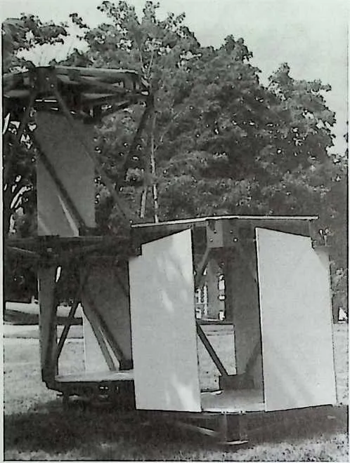
103 Figure 16.20 Quarter-scale model of several hexmods. Partial view. (Source: J. F. Gabriel and J. A. Mandel, ‘‘A Space Frame Building System for Housing,’’ Proceedings of the Third International Conference on Space Structures, H. Nooshin, ed., Elsevier, London, 1984, p. 1057, Fig. 11. Reprinted with permission of Chapman and Hall, Cheriton House, North Way, Andover, HANTS, AP10 5BE, UK.)
104 mechanical help. Alternatively, hexmods and CCs could be preassembled on the ground and lifted in place with the help of a crane. A third possibility would consist of finishing hexmods as individual rooms off site (Figures 16.20 and 16.21).
105 The hexmod system as described here uses diagonals of small cross section to limit the wall thickness, especially if cladding is added on both sides of the diagonals, interior and exterior. This restriction to the size of diagonals makes the

107 Figure 16.21 Simplified drawing of a large assemblage of hexmods. Most CCs are deleted to show the points of contact between hexmods. This is only a diagram, not a realistic design. A building of this size would have to rely on a complementary structural framework.
108 hexmod system practical only for buildings of limited height We will see later on that there are other ways to use its space-making potential in very tall buildings.
109 THE star beam
110 Although the hexmod building system makes possible the conception and the construction of many building forms, it has limitations. All building systems do. We could retain the same floor structure, with all its advantages, and select a different set of diagonals between floors. The building blocks could be dispensed with but would the structural framework remain stable? Could we create different, more open architectural spaces? Might these possibly lend themselves to architectural programs that hexmods could not accommodate?
111 In a hexmod framework, the floor structure is made of hexagonal subassemblies interconnected by their comers. The triangles formed in the intervals between hexagons can give each CC, UC, or LC the shape of a six-pointed star (Figures 16.8 and 16.9). We could describe the floor structure as entirely made of star shapes centered on CCs and connected laterally to one another by their points.
112 Consider one of these stars and the corresponding one on the floor above. They are not at the vertical of one another. Indeed, they are shifted. Connect the points of one star to the points of the other with diagonals and you will have a three-dimensional module, a geometrically rigid configuration that will be our new ‘‘building block.’’ We call this a star module because of the shape of the chords. There are eight faces altogether to what amounts to a convex polyhedron. What opposes its collapse is the fact that the ten diagonals form eight triangular frames situated in four different planes (Figure 16.22).
113 The star module is interesting in spatial terms. The diagonals divide themselves into two groups of five, symmetrically distributed on either side of the long axis. They frame a single space between them, 8 m wide. This space
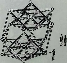
115 Figure 16.22 A star is a CC extended by six triangles. The star module consists of two star shapes located on consecutive floors and connected to each other. Ten diagonals connect the points of one star to the points of the other. The triangular frames formed by the diagonals and the different planes in which these triangles are found add up to an inde-formable configuration. (Source: J. F. Gabriel and J. A. Mandel, ‘‘The Star Beam,’’ in Shell and Spatial Structures Engineering, F.L.LB. Carneiro, A. J. Ferrante, R. C. Batista, and R.
116 L. Palanco, eds., Pentech Press, London, 1984, p. 14, Fig. 2.)
117 can be entered from both ends through rectangular bays that measure 4 m across. The space within then widens from 4 m at one end, to 8 m in the middle, and narrows down again to 4 m at the other end.
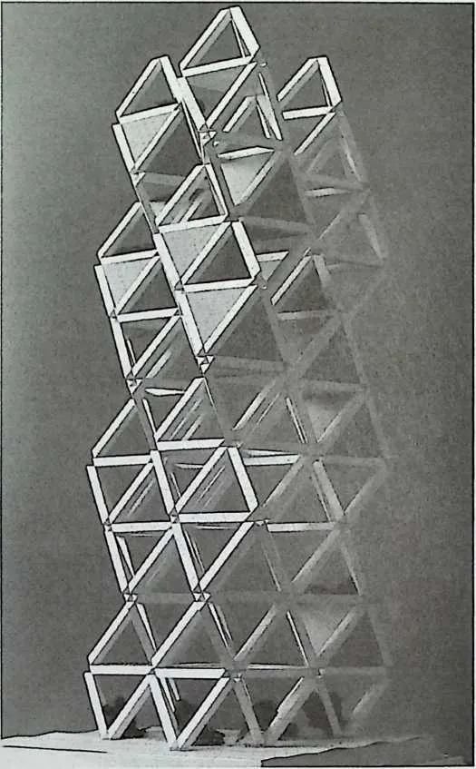
118 Let us see how this module combines with others, first vertically, then horizontally, then in all directions. It is a directional shape, in the sense that the stars that form its floor and its roof are shifted in the direction of the six diagonals that are parallel to one another. Matching points of the two stars are found at the top and at the bottom of a diagonal. Because there are three sets of diagonals, each leaning in a different direction, star modules can be rotated 120° one at a time, as they are piled up on top of one another. The result is an elegant configuration approximating a helicoid and as close to the vertical as can be obtained from star modules (Figure 16.23).
119 A major difference between the hexmod system and the star system is this: Hexmods enclose portions of space and they mold the spaces between them into other shapes. The star module creates only one space. It is a ‘‘space filler’’ by itself, meaning that it can organize all space without gaps or overlaps. Therefore, minimal towers like the one just described can be juxtaposed to
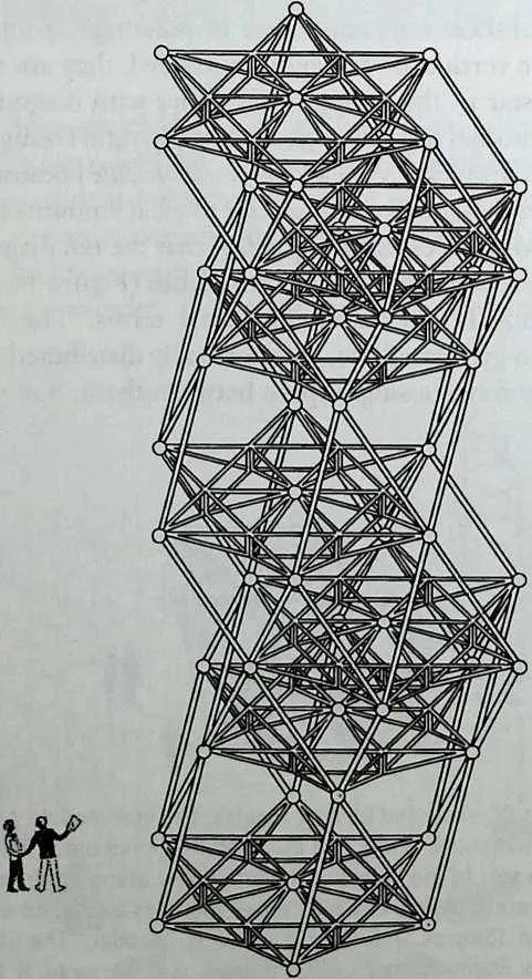
121 Figure 16.23 This minimal tower is made of star modules, each one rotated by 120° in relation to the one immediately below. Because the imaginary line connecting the centers of the stars is parallel to one set of diagonals, there are only three orientations possible for a star module. Consequently, the fourth module has the same orientation as the first one and the two share precisely the same vertical projection. (Source: J. F. Gabriel, ‘‘Dwelling in Space Structures,’’ in Studies in Space Structures, H. Nooshin, ed., Multi-Science Publishing, Brentwood, UK, 1991, pp. 69–86, Fig. 6. Reprinted with permission.).
122 one another, as many times and in any direction as desired, if what the designer wants is a structural matrix approaching the vertical. The following configurations that are derived from the star module are mostly space fillers (an unfortunate term, because the modules organize space but do not fill it).
123 Superimposing star modules without changing their orientation results in leaning towers, or pods. This suggests that they should, perhaps, lean against one another and form pyramidal/tetrahedral constructions (Figures 16.24 and 16.33).
124 There are several possible ways to assemble star modules horizontally. The most obvious is to line up their larger openings in order to form a throzigh-truss (Figures 16.25 and 16.26). The space within is entered at one end through a 4-m-wide bay, then the space swells to 8 m, to return to 4 m, and so on, until the user reaches the other end and leaves through a last 4-m-wide bay.
125 As with hexmods, space is defined laterally by vertical planes applied against the diagonals. And, as in hexmods, natural passageways are also found wherever two diagonals form an A by meeting overhead. Needless to say, windows could be installed where doors are not wanted (Figures 16.27 and 16.28).
126 We have seen that star modules can be superimposed in two different
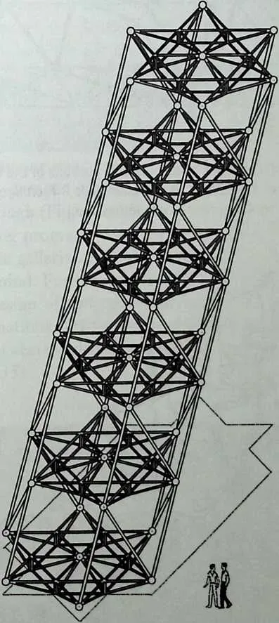
128 Figure 16.24 Here, the star modules all face the same direction. They are superimposed to form a rectilinear tower that leans at an angle of 54° 6', which is the angle formed between a diagonal and the ground. (Source: J. F. Gabriel, ‘‘Space Frames: The Space Within—A Guided Tour," International Journal of Space Structures, Vol. 1, No. 1,1985, p. 9, Fig. 10. Reprinted with permission of Elsevier Science Ltd, The Boulevard, Langford Lane, Kidlington 0X5 1GB, UK.)
129 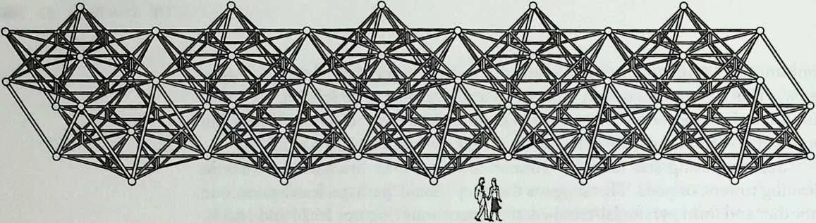
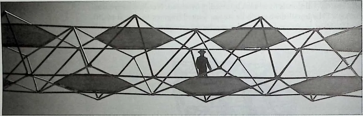 Figure 16.27 This figure shows the space within a five-unit star beam. The
roof has been deleted, but the stars are clearly visible on the floor. Vertical cladding
coincides with diagonals and lateral openings are found where diagonals form A-frames.
Depending on the location of a star beam within a larger structural context, these
openings would frame doors or windows. The floor structure has been expanded laterally.
Otherwise, this structure is identical to that shown in Figure 16.25. (Source: J. F.
Gabriel, ‘‘La Poutre-Etoile," Techniques et Architecture, No. 320, Paris, 1978, p. 70,
Fig.
Figure 16.27 This figure shows the space within a five-unit star beam. The
roof has been deleted, but the stars are clearly visible on the floor. Vertical cladding
coincides with diagonals and lateral openings are found where diagonals form A-frames.
Depending on the location of a star beam within a larger structural context, these
openings would frame doors or windows. The floor structure has been expanded laterally.
Otherwise, this structure is identical to that shown in Figure 16.25. (Source: J. F.
Gabriel, ‘‘La Poutre-Etoile," Techniques et Architecture, No. 320, Paris, 1978, p. 70,
Fig.
130 Figure 16.25 The star beam is, in fact, a hollow, or ‘‘through," truss. The width of the open space within alternates between 4 and 8 m. There are five star modules here, connected in such a way that their large openings coincide. This configuration is geometrically rigid (Source: J. F. Gabriel, ‘‘From Space Lattice to Architecture,’’ Bulletin of the International Association for Shell and Spatial Structures, Vol. 20, No. 2,1979, pp. 19–23, Fig. 12. Reprinted with permission.)
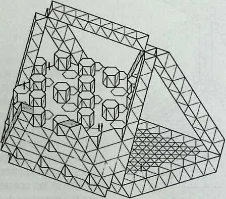
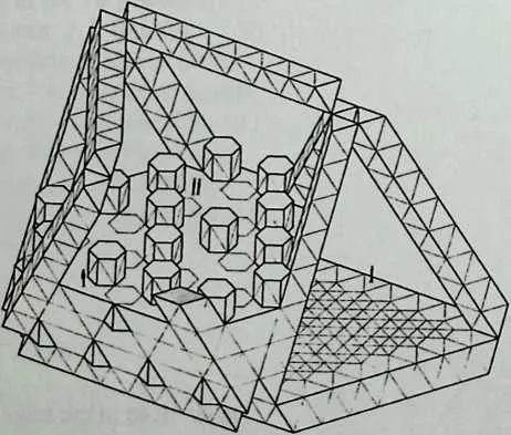
131 Figure 16.26 Schematic model of a star beam. The only portions of the floor planes to be shown are the CCs. (Source: J. F. Gabriel, ‘‘La Poutre-Etoile," Techniques et Architecture, No. 320, Paris, 1978, p. 70, Fig. 4. Reprinted with permission.)
132 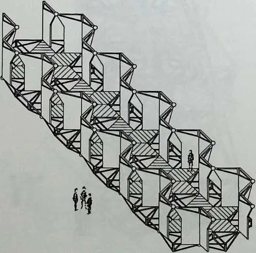 3. Reprinted with permission.)
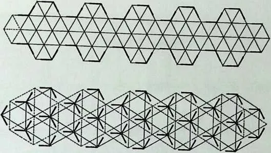
134 Figure 16.28 Top: Simplified plan of a five-unit star beam. Diagonals and chords coincide, as described in the first part of the chapter. Bottom: A similar configuration based on the conventional three-way space frame. Chords and diagonals do not coincide. (Source: J. F. Gabriel and J. A. Mandel, ‘‘The Star Beam,’’ in Shell and Spatial Structures Engineering, F. L. L. B. Carneiro, A. J. Ferrante, R. C. Batista, and R. Palanco, eds., Pentech Press, London, 1984, p. 16, Fig. 4.)
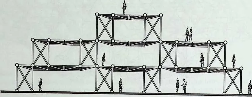
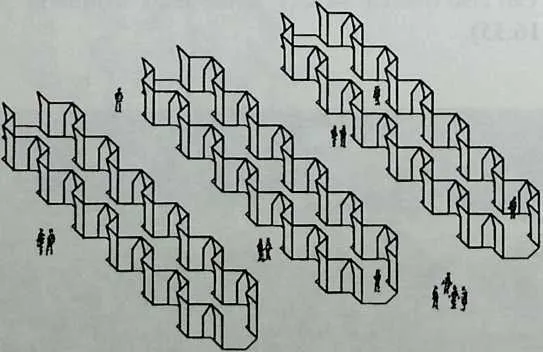
135 ways: They can be joined horizontally to form through-trusses, and they can also be juxtaposed laterally to partition all space. In all these formal arrangements, interior spaces are identical, and one might think that the only difference between one building and another would come from their overall shape. This impression would be true if the spanning capabilities of the star beam were overlooked. Indeed, combinations of star modules are endless and so is the variety of spaces generated by these combinations. There is an especially interesting one because it is simplicity itself, and I find the yield spectacular. It consists of using one star beam to cover the space between two others. This results in 8-m-wide open spaces, alternating with 12-m-wide spaces as one walks in and through (Figures 16.29 to 16.32).
136 Many building programs require galleries lined up with rooms wider or narrower than the galleries. Schools, museums, shopping centers, offices, and hotels come to mind. Furthermore, applications of star modules need not be limited to the design of stiff rectilinear buildings. Hexagonal and Y-shaped plans and combinations of these can be made (Figures 16.33 and 16.34). Finally, star beams can also overlap in such a way as to form large pyramidal structures (Figure 16.35).
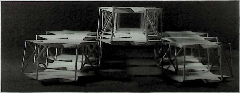
138 Figure 16.29 The width of the space within a star beam varies from 4 to 8 m. When a star beam is used to span the interval between two more star beams, the width of the space between these reaches 12 m, with a minimum of 8 m at its narrowest.
139 Figure 16.30 The purpose of this diagram is to show how star beams can create wider spaces than the spaces they contain. (Source: J. F. Gabriel and J. A. Mandel, ‘‘The Star Beam,’’ in Shell and Spatial Structures Engineering, F. L. L B. Carneiro, A. J. Ferrante, R.
140 C. Batista, and R. L. Palanco, eds., Pentech Press, London, 1984, p. 18, Fig. 7.)
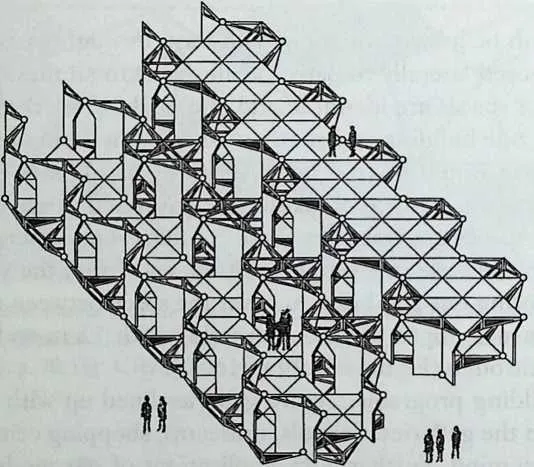
143 Figure 16.31 Detail of the configuration shown in Figure 16.29. The roof of the lower star beam is deleted so that the space within can be seen. (Source: J. F. Gabriel and J. A. Mandel, ‘‘The Star Beam,’’ in Shell and Spatial Structures Engineering, F. L. L. B. Carneiro, A. J. Ferrante, R. C. Batista, and R. L. Palanco, eds., Pentech Press, London, 1984, p. 20, Fig. 11.)
144 Figure 16.32 If star beams are used to cover the interval between other star beams, this is how the spaces on the lower level will be, within the star beams and between them. (Source: J. E Gabriel and J. A. Mandel, ‘‘The Star Beam,’’ in Shell and Spatial Structures Engineering, F. L. L. B. Carneiro, A. J. Ferrante, R. C. Batista, and R. L Palanco, eds., Pentech Press, London, 1984, p. 19, Fig. 9.)
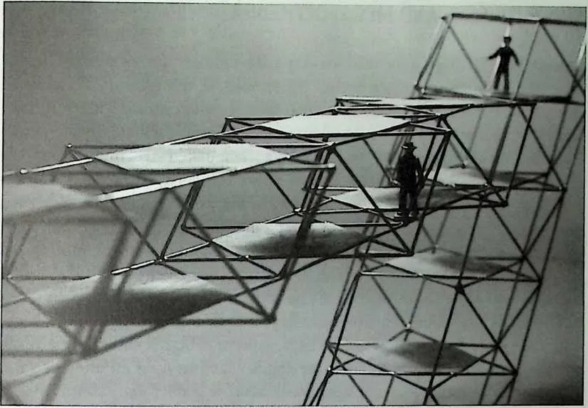
146 Figure 16.33 Schematic model of a star beam supported by a leaning tower of the type shown in Figure 16.24. It is worth observing that the space molded by the star beam is not interrupted, or even modified, by the presence of the tower. It continues right through it, totally unaffected in its shape. (Source: J. F. Gabriel, ‘‘La Poutre-Etoile,’’ Techniques et Architecture, No. 320, Paris, 1978, p. 70, Fig. 5. Reprinted with permission.)
147 Figure 16.34 Although essentially rectilinear, star beams can generate rich and varied building forms, as this diagram shows. The dotted line indicates the outline of the floor above. (Source: J. F. Gabriel and J. A. Mandel, ‘‘The Star Beam,’’ in Shell and Spatial Structures Engineering, F. L. L. B. Carneiro, A. J. Ferrante, R. C. Batista, and R. L Palanco, eds., Pentech Press, London, 1984, p. 21, Fig. 12.)
148 Figure 16.35 Another relationship between star beams, where one of them would cover most of the one immediately below. Although there is little difference in structural continuity between this configuration and the one shown in Figure 16.31, the architectural results are fundamentally dissimilar. This drawing does not represent a finished building; it only shows different construction stages of a building. (Source: J. F. Gabriel, ‘‘From Space Lattice to Architecture,’’ Bulletin of the International Association for Shell and Spatial Structures, Vol. 20, No. 2,1979, p. 23, Fig. 14.)
150 SPACE TRUSSES AND MEGAPOLYHEDRA
151 Should space frames also be used for very tall buildings? Yes, of course, for the taller the building, the more critical the stresses. A triangulated structure is not necessary for small buildings such as houses, where stresses are minimal. Square frames will do. However, when in 1889 Gustave Eiffel conceived and built ‘‘la tour de 300 metres,’’ he designed a triangulated structure. So did the engineer Fazlur Khan in 1967 for the John Hancock Tower in Chicago, which, at the time, was the tallest building in the world. And so did I. M. Pei and Partners at the Bank of China building in Hong Kong more recently.5
152 It is malicious to say that architects dream up a building form and turn to a structural engineer to do whatever is necessary to make it stand up. This is a caricature of the architect. It is also a myth to give credit to engineers for always thinking rationally. However, why is it that so many architects and engineers conceive tall structures as aggregates of cubes? A cubic frame is not a sound structural unit until cross-bracing is added to it, as an afterthought. And a cubic volume does not necessarily make a good room. Would it not make more sense to approach the design of tall buildings from a structural frame with integrated triangulation in mind? One suspects that reluctance to do so is based on the widespread myth of the uninhabitable triangular form.
153 Buildings with sharp comers can indeed be unfriendly. A room with a triangular plan is likely to be unfriendly, too, but six triangles can form a hexagon, with 120° angles, which are friendlier than right angles. Frank Lloyd Wright remarked on that in the following words: ‘‘…I am convinced that a cross section of honeycomb has more fertility and flexibility where human movement is concerned than the square. The obtuse angle (120 degrees) is more suited to human ‘‘to and fro’’ than the right angle.’’6 A room shaped Eke a pyramid is also likely to make an uncomfortable space, especially if it comes with a triangular base, as tetrahedra do. However, a hexmod, which is a modified octahedron, makes as friendly a room as any cubic or shoebox-like room. Probably a friendlier one. And hexmods are found in space frames, not in cubic frameworks.
154 Another reason for the puzzling ubiquity of the rectangular framework in tall buildings may be found in another widespread myth: the belief that columns must be vertical to do their job. Paradoxically perhaps, columns can be replaced by diagonals, whereas columns, in and of themselves, cannot ensure the wind-bracing of a structure. Even at the scale of furniture, it is easy to see that four sticks under a board do not make a table, unless the connections are made rigid. However, rigid connections have their price, which is excess material and inelegant structural workings.
155 What, then, if we conceived very large space frames? What sort of buildings would we be able to create? Would they be beautiful, practical, and lasting? Would they possibly have a potential not found in conventional buildings? Might they open up possibilities we do not dare to dream of because we do not know we have the means to realize them?7
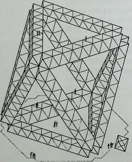
156 The concept of gigantic space frames is not new. Louis Kahn (with Anne Tyng), Buckminster Fuller, Yona Friedman, and Peter Cook are among the best known to have explored the idea.8 What is new here is the systematic use °f a 4-m octahedron as a conceptual building block containing enough space for a small room. Eight such octahedra, joined in a straight line to one another by a shared edge—here a strut—constitute our next module, which we will call the space truss. Tetrahedral shapes fit in the interstices between the octahedra and make the space truss rigid. Each one of our modular space trusses, 32 m long, comprises eight octahedra and 14 tetrahedra. Why eight octahedra? Because this is the number of 4-m octahedra that will make possible the erection of regular megapolyhedra with a standard space truss. It is also the largest preassembled module that can be moved to a construction site and raised without too much difficulty. Finally, shorter space trusses would be redundant and cumbersome (Figures 16.36 and 16.40).
157 The terms space truss and space frame are often given the same meaning. As there is no consensus among architects, engineers, morphologists, and historians, I hope the reader will bear with me and, for now, understand them in the sense I have intended them.
158 Eight-story octahedra and tetrahedra can be erected with the modular space truss, which is to say that mega-space frames can be erected with it. Whatever the orientation of a space truss in space—and six of them are possible as well as necessary—the orientation of all the 4-m octahedra remains the same, wherever their location in the structure. Although this is generally true in space frames, it cannot be repeated too often. Whether they belong to the three horizontal space trusses or to the three oblique ones, all the 4-m octahedra retain the same orientation in space.
159 In addition to the tetrahedron and the octahedron, three possible megapolyhedra are illustrated here: a cuboctahedron, a (so-called) truncated tetrahedron, and a (so-called) truncated octahedron. The cuboctahedron is fortunate in having a descriptive name, for it has the four square faces of a cube and the eight triangular faces of an octahedron (Figure 16.37). The same cannot be said of the other two polyhedra. They could, it is true, be obtained by a process of truncation, but they can also be the result of an additive process instead. Four octahedra can be seen in the drawing as entering into the for-

161 Figure 16.36 Top view, elevation, and side view of a space truss. Eight 4-m octahedra are joined together edge to edge. Interstitial spaces are filled by tetrahedra. (Source: J. F. Gabriel, ‘‘Multi-Layer Space Frames and Architecture,’’ Proceedings of the International Conference on Lightweight Structures in Architecture, Sydney, 1986, V. Sedlak, ed., Vol. 1, 1986, pp. 104–111, Fig. 2. Reprinted with permission).
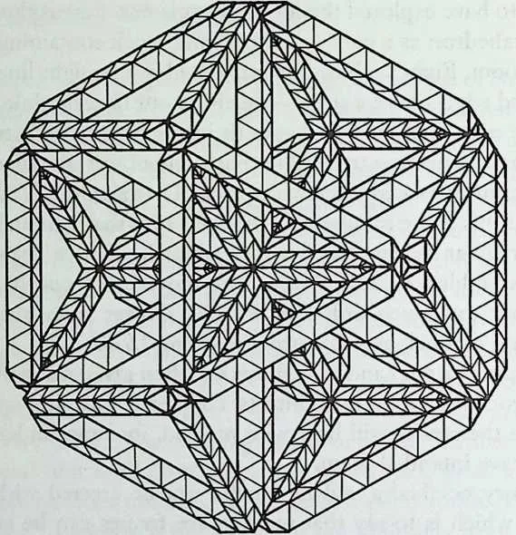
163 Figure 16.37 Top view of a cuboctahedron made of 36 interconnected space trusses. Six horizontal and six oblique space trusses meet at the center, which can be clearly seen. This is a 19-story structure. In addition to the 16 stories corresponding to two superimposed sets of oblique space trusses, there are three sets of horizontal space trusses, each a story high. In this and the following drawings, the physical connections between space trusses are not shown in their entirety. They would only obscure the picture. The shape of the connections is worth describing, even if it is difficult to describe clearly. In the case of 12 converging space trusses, a gap appears, the shape of which is a stellated octahedron, or Stella octangula. Each space truss is in contact with four others, but none can touch the space truss opposite. Converging space trusses generate an additional octahedron between them, each space truss contributing one of the 12 edges. Eight tetrahedra fill the interstices between the butts of the space trusses and the additional octahedron. (Source: J. F. Gabriel, ‘‘Megapolyhedra,’’ Proceedings of the IASS Symposium on Spatial Structures at the Turn of the Millennium, Copenhagen, 1991, T. Wester, S. J. Medwadowski, and I. Mogensen, eds., 1991, pp. 35–44, Fig. 7A.)
165166mation of the truncated tetrahedron. They are nestled among seven tetrahedra (Figure 16.38).
167As for the truncated octahedron, it includes half-octahedra in addition to complete octahedra and tetrahedra. The cuboctahedron has eight tetrahedra but comprises no complete octahedra, only six halves (Figure 16.39).
168The cuboctahedron shown here has 19 stories; the truncated tetrahedron also. The truncated octahedron would have 28 stories. Included in this count are the stories contributed by the horizontal space trusses.
169I am not recommending that buildings should adopt the shape of these megapolyhedra. I am showing them in the hope that they might open up new horizons in architecture and urban design. We are accustomed to buildings sitting squarely on the ground. We also expect buildings to fill up the totality of the space occupied by their structure. I am suggesting that, if we take advantage of the most efficient structural configuration available to us, which
170 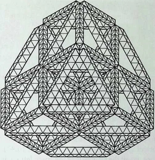 Figure 16.38 Top view of a truncated tetrahedron obtained by the aggregation of
fourmegaoctahedra and seven megatetrahedra.This also is a 19-story structure. (Source: J. F.
Gabriel, ‘‘Megapolyhedra,’’ Proceedings of the IASS Symposium on Spatial Structures at the Turn
of the Millennium, Copenhagen, 1991, T. Wester, S. J. Medwadowski, and I. Mogensen, eds.,
1991, pp. 35–44, Fig. 8.)
Figure 16.38 Top view of a truncated tetrahedron obtained by the aggregation of
fourmegaoctahedra and seven megatetrahedra.This also is a 19-story structure. (Source: J. F.
Gabriel, ‘‘Megapolyhedra,’’ Proceedings of the IASS Symposium on Spatial Structures at the Turn
of the Millennium, Copenhagen, 1991, T. Wester, S. J. Medwadowski, and I. Mogensen, eds.,
1991, pp. 35–44, Fig. 8.)
171 is that of the space frame, we could conceive structural frameworks at the urban scale rather than at the scale of individual buildings, and buildings could be hovering over the ground where necessary.
172 I would like to point out that our three polyhedra can be combined to form varied infinite structures. One pattern can be formed by using them all. Another pattern can be obtained from the exclusive use of truncated octahedra, and a third pattern is possible with octahedra and cuboctahedra. This is in addition to the octahedron-tetrahedron pattern. These infinite structures are compatible with one another and, naturally, with the underlying six-directional space lattice that originated them all. If I add that large open spaces can alternate with enclosed spaces without a breakdown in geometric continuity, it becomes clear
173 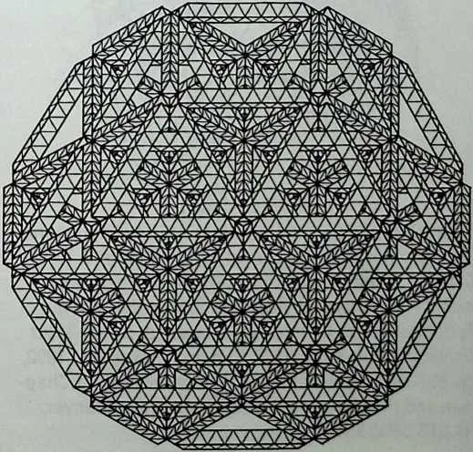 Figure 16.39 Top view of a truncated octahedron. Four of the eight hexagonal faces and
three of the six square faces can be recognized. This structure has 28 stories. Three sets of
oblique space trusses correspond to 24 stories and four sets of horizontal space trusses
correspond to four stories. (Source: J. F. Gabriel, ‘‘Megapolyhedra,'’ Proceedings of the
IASS Symposium on Spatial Structures at the Turn of the Millennium, Copenhagen,
1991, T. Wester, S. J. Medwadowski, and I. Mogensen, eds., 1991, pp. 35–44, Fig.
9.)
Figure 16.39 Top view of a truncated octahedron. Four of the eight hexagonal faces and
three of the six square faces can be recognized. This structure has 28 stories. Three sets of
oblique space trusses correspond to 24 stories and four sets of horizontal space trusses
correspond to four stories. (Source: J. F. Gabriel, ‘‘Megapolyhedra,'’ Proceedings of the
IASS Symposium on Spatial Structures at the Turn of the Millennium, Copenhagen,
1991, T. Wester, S. J. Medwadowski, and I. Mogensen, eds., 1991, pp. 35–44, Fig.
9.)
175176that we have a mind-boggling number of design options at our disposal for a truly spatial urbanism. All these possibilities depend on the prefabrication of a noncombustible space truss that can be securely attached to others.9
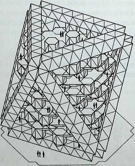
177So far, so good. We have a three-dimensional urban framework that can accommodate buildings. The next question is: What sort of buildings? Consider one of the simplest forms within the urban space frame: an octahedron. It is an eight-story space defined by space trusses (Figure 16.40). What structural system should be used to organize that space in architectural terms? Obviously, the answer is a system based on the same geometry as the space trusses; more precisely, a six-directional network of thin members attached to the space trusses. This network reintroduces the hexmod system with a fanfare: The thin members, stretched from one space truss to another, can now work more efficiently because they are put in tension. The structural capabilities of the hexmod system, limited to three or four stories, can be extended to eight stories within a framework of space trusses (Figures 16.41 and 16.42).
178The hexmod system does not use all the diagonals of the space lattice, but the diagonals it uses are continuous from one end of the building to the other. Some will be attached to space trusses and others will not, but none will have to be in compression for more than three consecutive stories.
179 igure 16.40 Twelve space trusses frame an eight-story Dctahedron. Next to it, on the ground, is a 4-m octahedron. It is the basic, conceptual "building block’’ of space truss and hexmod alike. (Source: J. F. Gabriel, ‘‘Skyscrapers or Space Towns,’’ in Developments in Structural Engineering, Proceedings of the Forth Rail Bridge Centenary Conference, He riot-Watt University, Edinburgh, 1990, B. H. V. Topping, ed., 1990, pp. 657–666, fig. 3. Reprinted with permission of Chapman and Hall, Cheriton House, North Way, Andover, HANTS SP10 5BE, UK.)
180 Figure 16.41 The hexmod system is used to implement the eight-story building shown here. (Source: J. F. Gabriel, ‘‘Skyscrapers or Space Towns,’’ in Developments in Structural Engineering, Proceedings of the Forth Rail Bridge Centenary Conference, Heriot-Watt University, Edinburgh, 1990, B. H. V. Topping, ed., 1990, pp. 657–666, Fig. 3. Reprinted with permission of Chapman and Hall, Cheriton House, North Way, Andover, HANTS SP10 5BE, UK.)
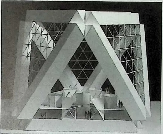
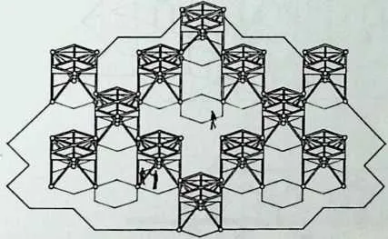
183 Figure 16.42 Model of the megaoctahedron with the lower two stories partially built with hexmods. (Source: J. F. Gabriel, ‘‘Space Frames: The Space Within—A Guided Tour,’’ International Journal of Space Structures, Vol. 6, No. 4,1991, pp. 287–295, Fig. 15. Reprinted with permission of Multi-Science Publishing, Brentwood, UK. Model by John Tanzi.)
184 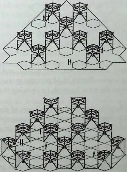 Figure 16.43 The bottom three stories of the building shown in Figure 16.41 are
represented sequentially here, from the bottom up. The drawings convey an airiness that is not
apparent in Figure 16.41. Careful experimentation showed that the elimination of certain
hexmods is possible. Three hexmods on the first floor, three on the second floor, and one on the
third floor were deleted, opening up large, column-free spaces. Upper caps show part of the floor
structure. Attentive examination of the drawings will allow the reader to verify the continuity of
diagonals from one floor to the next Hexagons shown on the floor of the upper two
stories indicate the location of the hexmods underneath. The presence of space trusses
interferes with six hexmods on the first floor. These hex-mods are deleted in Figure 16.41.
(Source: J. F. Gabriel, ‘‘Megapolyhedra,’’ Proceedings of the IASS Symposium on
Spatial Structures at the Turn of the Millennium, Copenhagen, 1991, T. Wester, S. J.
Medwadowski, and I. Mogensen, eds., 1991, pp. 35–44, Fig. 5A. Reprinted with permission of
T. Robbin, Engineering a New Architecture, Yale University Press, 1996, p. 94, fig.
7.17.)
Figure 16.43 The bottom three stories of the building shown in Figure 16.41 are
represented sequentially here, from the bottom up. The drawings convey an airiness that is not
apparent in Figure 16.41. Careful experimentation showed that the elimination of certain
hexmods is possible. Three hexmods on the first floor, three on the second floor, and one on the
third floor were deleted, opening up large, column-free spaces. Upper caps show part of the floor
structure. Attentive examination of the drawings will allow the reader to verify the continuity of
diagonals from one floor to the next Hexagons shown on the floor of the upper two
stories indicate the location of the hexmods underneath. The presence of space trusses
interferes with six hexmods on the first floor. These hex-mods are deleted in Figure 16.41.
(Source: J. F. Gabriel, ‘‘Megapolyhedra,’’ Proceedings of the IASS Symposium on
Spatial Structures at the Turn of the Millennium, Copenhagen, 1991, T. Wester, S. J.
Medwadowski, and I. Mogensen, eds., 1991, pp. 35–44, Fig. 5A. Reprinted with permission of
T. Robbin, Engineering a New Architecture, Yale University Press, 1996, p. 94, fig.
7.17.)
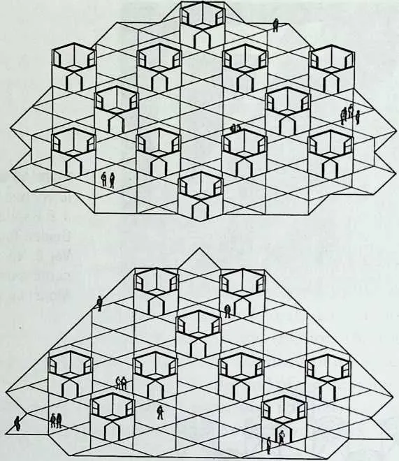
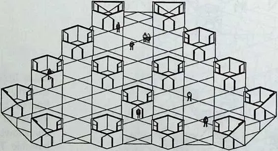
186 Figure 16.43 shows the hexmod structure of the first, second, and third stories, with the lower story at the bottom. Figure 16.44 provides more information on the relationships between the same hexmods by showing them as enclosed rooms.
187 However, an eight-story building like this is only a small part of the sort of urban ensembles that are feasible. Space trusses arranged in megaoctahedra and megatetrahedra create powerful frameworks that should find their applications in vast structures. As an example, I would like to discuss briefly a study for a 135-story structure. It is a relatively conservative design, in the sense that it resembles a skyscraper in some ways. The reason for this choice is that elevators that run in vertical shafts are more acceptable to a conservative public. Also, vertical shafts occupy less space than oblique shafts. Settlements nor-
188 Figure 16.44 Whereas the hexmods were drawn as structural elements in Figure 16.43, they are shown here as rooms, with enclosures. (Source: J. F. Gabriel, ‘‘Space Frames: The Space Within—A Guided Tour,’’ International Journal of Space Structures, Vol. 6, No. 4,1991, pp. 287–295, Fig. 14. Reprinted with permission of Multi-Science Publishing, Brentwood, UK.)
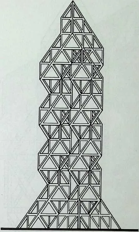
190 Figure 16.45 Space trusses can be assembled in multilayer frameworks of vast dimensions. Here is 3135-story structure composed of megaoctahedra and megatetrahedra arranged vertically in three identical helicoids. (Source: J. F. Gabriel, ‘‘Dwelling in Space Structures,’’ in Studies in Space Structures, H. Nooshin, ed., Multi-Science Publishing, Brentwood, UK, 1991, pp. 69–86, Fig. 18. Reprinted with permission.)
192193mally occur along roads, and elevators are modem roads. They determine the shape of vertical configurations (Figures 16.45 and 16.50).
194The similarities with a skyscraper end here. The greatest difference after the adoption of oblique, rather than vertical, supports is the division of the building bulk into nearly independent units. Each unit is an eight-story module, already familiar to us (Figure 16.41), fitted into an octahedral frame of space trusses. Because of the morphology of a space frame, which makes it impossible for an octahedron to share a face with another, each unit is practically freestanding. No unit is ever found directly above or below another; it is always offset. For this and other reasons, the concept is not so much of a building as of a space town.10
195To bring the configuration closer to the vertical, megaoctahedra are arranged in a helicoidal pattern. They are connected to one another by megatetrahedra, which render the whole rigid. The description of an unfamiliar pattern often sounds complicated but, more often than not, the pattern itself is simple: In the present case, it consists of one tetrahedron above and one under the octahedron. Together, the three polyhedra add up to a simple, six-sided geometric solid (called an oblate rhombohedron) resembling an elongated cube (Figure 16.46).
196The entire structure is made of three helicoids attached to one another for stability, surrounding an open space for elevators. Every ninth floor, a platform
Figure 16.46 A detail of one of the helicoids. There is a tetrahedron above, and another one under each octahedron. The resulting form, which has six rhombic faces, is an oblate rhombohedron. The drawing shows four of these, connected by their faces. The uppermost oblate rhombohedron is in contact, tip to tip, with the one at the very bottom. (Source: J. F. Gabriel, ‘‘Dwelling in Space Structures,’’ in Studies in Space Structures, H. Nooshin, ed., Multi-Science Publishing, Brentwood, UK, 1991, pp. 69–86, Fig. 17. Reprinted with permission.)197
connects the helicoids. This is where the main elevators discharge their passengers, who will find other, smaller elevators within the eight-story unit where they five, work, or do other business. The platform functions as a fire barrier: The horizontal space trusses are linked by two reinforced concrete slabs that would prevent an eventual fire from spreading. People escaping from the building will reach safety by moving on to the next helicoid (Figure 16.47).
198A space town has certain advantages over a conventional building. Depending on functional needs and/or climatic conditions, the large tetrahedral space adjacent to each eight-story unit can be made into a garden or an ‘‘atrinm.’’ This space can also be used for expansion of the eight-story unit if it becomes too small (Figures 16.48 to 16.50).
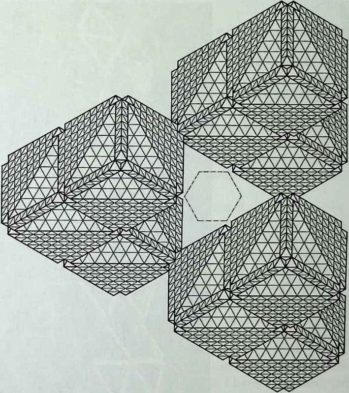
200 Figure 16.47 Top view of three helicoids forming a space town. Hexmods are used in the building units, which occupy the octahedral spaces framed by space trusses. Glass walls enclose building units. The hexagon at the center outlines the elevators and stairs zone.
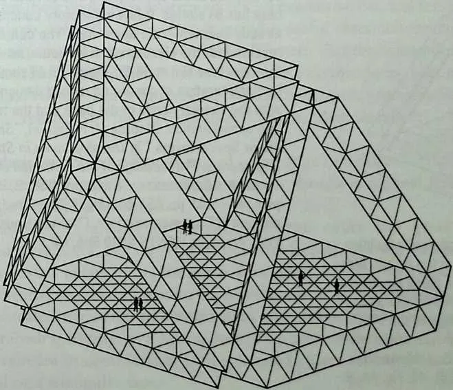
202 Figure 16.48 In the helicoids a tetrahedron is adjacent to every octahedron. The building unit housed in the octahedron can expand in the tetrahedral space if necessary. An alternative use for that space is an open garden or an enclosed greenhouse.
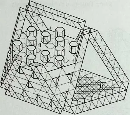
203 Figure 16.49 Two stages of the construction of a building unit. From the bottom up, construction of the fourth, fifth, and sixth stories. Hexmods push out the glass enclosure where it interferes with their formal integrity. (Source. J. E Gabriel, ‘‘Megapolyhedra,’’ Proceedings of the IASS Symposium on Spatial Structures at the Turn of the Millennium, Copenhagen, 1991, T. Wester, S. J. Medwad-owski, and I. Mogensen, eds., 1991, PP-35–44, Fig. 4A, B, C. Reprinted with permission.)
204 Figure 16.50 Model of the three helicoids forming the bare bones of the space town. The structure shown here has 89 stories. A few eight-story buildings are already inserted in the upper part. The central space reserved for the elevators can be better seen in the top view (see Figure 16.47). Figure 16.45 shows a similar configuration at a more advanced design stage, with the special needs of the base and the top taken into consideration. (Source: J. F. Gabriel, ‘‘Skyscrapers or Space Towns,’’ in Developments in Structural Engineering, Proceedings of the Forth Rail Bridge Centenary Conference, Edinburgh, 1990, B. H. V. Topping, ed„ 1990, pp. 657–666, Fig. 1. Reprinted with permission of Chapman and Hall, Cheriton House, North Way, Andover, HANTS SP10 5BE, UK.)
206 SPACE FRAMES AND POLYHEDRA
207 This chapter begins with a study of the space within two polyhedra that are closely related to the cube: the octahedron and the tetrahedron. These are the modules that form space frames. They are most habitable when their faces are deleted and only their edges remain as the integral part of a space lattice structure. Vertical enclosures and partitions can then be introduced to create a rather conservative architectural environment.
208 Although the process yields simple, honeycomb-like clusters of rooms, further investigation reveals that richer patterns are also possible. Hexmods, star beams, and megapolyhedra describe some of these patterns. They are variations on a single theme, which is the transformation of an octahedron into a hexagonal, prismatic space.
209 Although intimately related, the hexmod and the octahedron bear little resemblance to one another. From an architectural point of view, the most distinctive feature of polyhedra is their oblique walls. To some critics, this appears to be their most disturbing attribute. Regardless of whether one likes or dislikes oblique walls, it could be argued that the substitution of vertical planes for oblique ones is a betrayal of the fundamental nature of polyhedra. But what of livability? What of the mental and physical comfort of the dweller? Do oblique walls make a space impossible to live in? Certainly not. But how serious an impediment are they to livability? The question must be examined closely.
210 From studies conducted over several years with students from various universities, including Syracuse, Harvard, and MIT, I learned that many polyhedra are not only habitable but they also have a rich architectural potential when used as the modules of infinite structures. They all cannot be dealt with here, but the following list may be a starting point for readers interested in doing research on their own. This is certainly not an exhaustive list, and it is not presented in any particular order, but it includes useful clues concerning viable positions of polyhedra in space. By ‘‘viable,’’ I mean that the orientation of the polyhedra relative to the ground is such that the interior spaces meet essential architectural requirements. For ease of visualization, orientation is indicated by the words ‘‘resting’’ or ‘‘poised’’ and should not be taken literally.11
- Cubes, resting on a face or poised on an edge or a node.
- Truncated octahedra, resting on a square face, a hexagonal face, or an edge shared by hexagons.
- Truncated octahedra in combination with cubes and great rhom- bicuboctahedra, resting on an octahedral face or on a square one.
- Truncated cubes in combination with great rhombicuboctahedra and truncated tetrahedra, resting on a hexagonal or an octagonal face.
- Truncated octahedra in combination with cuboctahedra and truncated tetrahedra, resting on a square face or on a hexagonal one.
- Octahedra in combination with truncated cubes, resting on an octahedral or a triangular face.
- Octahedra in combination with cuboctahedra, resting on a square face or on a triangular one.
- Octahedra and tetrahedra, resting on a face (three-way space frame) or poised on a node (two-way space frame) or poised on an edge.
- Small rhombicuboctahedra in combination with cubes and tetrahedra, resting on a square face or poised on a node.
- Small rhombicuboctahedra in combination with cubes and cuboctahedra, poised on a node or resting on a square or a triangular face.
- Rhombic dodecahedra resting on a face or poised on a node (nodes are either at the intersection of three or four faces).
211 What system of polyhedra shall we choose to investigate? Although spatially and formally different from one another, most polyhedra have common characteristics, and one of them is oblique walls. Because we normally stand upright and are accustomed to having vertical walls around us, these provide a useful reference. It can be argued, however, that not all the walls surrounding us need be vertical. Only a few are useful for reference. Most habits dull the senses, and the vertical-wall habit is no exception: In many cases vertical walls fail to interest us because they are all around us. If, on the other hand, the actual enclosure of a space is made of oblique walls, our awareness of being sheltered will be enhanced. And so will be our sense of being in a specific place, with all its implications, including an increased sense of identity for ourselves. Knowing where we are goes a long way toward telling us who we are.12
212 One of the most commonly heard arguments against oblique walls is that they waste space. If a wall leans inward, it will be said to interfere with headroom. If a wall leans outward, it will be presumed to be unusable in itself and to generate an unusable space in front of it. Yet a look at traditional building plans shows that a considerable amount of floor space is taken up by closets and other storage spaces. This is wasteful, and it is a consequence of the exclusive use of vertical walls: In conventional buildings, that is, ‘‘cubic’’ buildings, closets must occupy floor space because there is no other place for them. On the contrary, walls that lean out make room for storage without taking up any floor space. A vertical plane, placed in front of the oblique wall, supplies both the space for storage and the wanted vertical surface for reference. Many other ingenious uses have been proposed for spaces found near oblique walls.13
213 Almost any single polyhedral form can be used to explore the advantages or disadvantages of oblique walls—but only to a certain point. A better, more comprehensive picture is obtained from polyhedra in clusters. Because I have looked more closely at combinations of truncated octahedra, cuboctahedra, and truncated tetrahedra than at any other infinite structure, I propose this system for our case study (Figures 16.51 and 16.52).
214 As already mentioned, the names of both the truncated octahedron and the truncated tetrahedron are somewhat misleading. Although it is true that these forms could result from a subtractive process of truncation, it is more significant for us to consider them as compound forms, obtained from the addition of tetrahedra to octahedra. That their names are misleading cannot be helped, but that the same names are cumbersome can be remedied: From
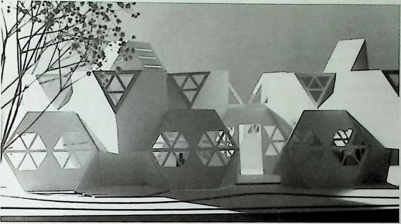
216 Figure 16.51 Design study for a kindergarten by Hans Graf. The formal components are the truncated tetrahedron, the cuboctahedron, and the truncated octahedron (TT, CO, and TO). The implicit layering of these polyhedra made it possible to introduce two simultaneous scales: Rooms are successfully planned for little human beings whose height is approximately half that of the others. (Source: J. E Gabriel, ‘‘The Architectural Potential of Polyhedra,’’ in Space Structures, G. A. R. Parke and C. M. Howard, eds., Thomas Telford, London, 1993, pp. 2025–2032, Fig. 6. Reprinted with permission. Photo: J. F. Gabriel.)
217 here on, we will call the truncated octahedron TO, the cuboctahedron, CO, and the truncated tetrahedron, TT.
218 If the octahedra used to form TOs, COs, and TTs are the size of hexmods, the TO will be a three-story unit, whereas both the CO and the TT will be two-story units (Figure 16.53).
219 Ideally, a building matrix should accommodate both large and small habitable spaces. The TO, the CO, and the TT can contain and determine the shape of large rooms, which will be as wide as they themselves are. As for their height, it can be one to three stories. For the space within these rooms to be entirely free of structural elements, the octahedra and tetrahedra that were originally used to shape it would have to remain purely conceptual (Figures 16.54 to 16.57).
220 If the structural system used in the building is a multilayer space frame, it will have to be external to the larger rooms. For this to be possible, a choice must be made between TOs, COs, and TTs. Where will the large, open spaces be created? The structural space frame cannot be eliminated from all polyhedral spaces at the same time. Many options are available. For instance, TOs can be ‘‘hollowed out,’’ leaving COs and TTs to carry the structural framework or, conversely, the TOs will consist of three stories of space frames and the open spaces will be in COs and TTs. The choice will be made on the basis of programmatic and functional needs. As to the smaller rooms, they can be found within the space frame itself, most likely in the shape of hexmods. Visually as well as spatially, the result of this conceptual approach will be buildings combining the form language of the hexmod system—an aggregate of hexagonal prisms—and that of polyhedra retaining their oblique faces.14
221 Figure 16.52 The six layers of this configuration, clearly visible, suggest a six-story structure. This is the scale adopted for the rest of this discussion. A TO divides itself spontaneously into three layers, whereas a CO and a TT divide themselves into two. COs always share their triangular faces with TTs in this pattern. The large space at the core is a TO. Each of its six square faces is shared with a CO. Its eight hexagonal faces can only be shared with TTs. There are four TTs in the model, all straight side up. (Source: J. F. Gabriel, ‘‘Space Frames and Polyhe-dra,’’ in Spatial, Lattice and Tension Structures, Proceedings of the IASS-ASCE International Symposium, J. Abel, J. Leonard, and C. Penalba, eds., 1994, pp. 1037–1044, Fig. 1. Reprinted with permission of the ASCE.)
222 Figure 16.53 The relationship between the polyhedra of an infinite structure is fixed. A vertical sequence reveals this relationship: From the bottom up, four elements complete the inventory: a CO, a TT, a TO, and a TT again. On top of that, another CO signals the beginning of a new cycle. The TT appears twice, in upright position above and inverted below. In this drawing proportions were changed for experimental purposes, but the topology of the system is not affected. (Source: J. F. Gabriel, ‘‘Polyhedra: Skin and Structure,’’ Application of Structural Morphology to Architecture, Proceedings of the Second International Seminar on Structural Morphology, R. Holler, J. Hennicke, and F. Klenk, eds., 1994, pp. 37–46, Fig. 2. Reprinted with permission of Institute for Lightweight Structures, University of Stuttgart)
223 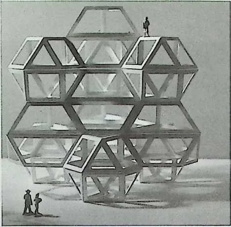
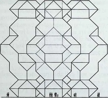
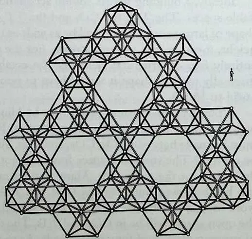 Figure 16.54 Horizontal sections engage all the polyhedra of the system and
reveal their relationships. Here, a CO, at the center is connected with three TTs by their
triangular faces. These TTs are ‘‘upside down,’’ and the level involved is the upper one. The TTs,
in turn, are connected with six CO|S, and so on. There is a total of seven COs and six TTs
in the configuration represented. There are also three TOs, with their interiors free
of structural members: Their outer form is defined by the continuous space frame
found in adjacent TTs and COs. The larger rooms required in most building programs
would be accommodated in the TOs. The space frame would accommodate the smaller
rooms and also assume a structural function. Structural members that indicate the
outline of polyhedral fragments are shown in black. The space frame is completed
with structural members shown white. On this story, passing directly from a CO to a
TT is impossible. To solve this problem, hexmods should replace the octahedra of
the space frame. (Source: J. F. Gabriel, ‘‘Polyhedra in Architecture,’’ International
Journal of Space Structures (Special Issue on Morphology and Architecture), H. Lalvani,
ed., 1996, Fig. 8. Reprinted with permission of Multi-Science Publishing, Brentwood,
UK.)
Figure 16.54 Horizontal sections engage all the polyhedra of the system and
reveal their relationships. Here, a CO, at the center is connected with three TTs by their
triangular faces. These TTs are ‘‘upside down,’’ and the level involved is the upper one. The TTs,
in turn, are connected with six CO|S, and so on. There is a total of seven COs and six TTs
in the configuration represented. There are also three TOs, with their interiors free
of structural members: Their outer form is defined by the continuous space frame
found in adjacent TTs and COs. The larger rooms required in most building programs
would be accommodated in the TOs. The space frame would accommodate the smaller
rooms and also assume a structural function. Structural members that indicate the
outline of polyhedral fragments are shown in black. The space frame is completed
with structural members shown white. On this story, passing directly from a CO to a
TT is impossible. To solve this problem, hexmods should replace the octahedra of
the space frame. (Source: J. F. Gabriel, ‘‘Polyhedra in Architecture,’’ International
Journal of Space Structures (Special Issue on Morphology and Architecture), H. Lalvani,
ed., 1996, Fig. 8. Reprinted with permission of Multi-Science Publishing, Brentwood,
UK.)
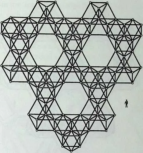
225 Figure 16.55 This horizontal section shows the story directly above that of Figure 16.54. The upper half of a CO can be recognized at the center. It is connected with three other TTs, but these are ‘‘straight side up,’’ and they are located above TOs. There are also three TOs, located above the ‘‘upside-down’’ TTs. (Source: J. F. Gabriel, ‘‘Polyhedra in Architecture,’’ International Journal of Space Structures (Special Issue on Morphology and Architecture), H. Lalvani, ed., 1996, Fig. 5. Reprinted with permission of Multi-Science Publishing, Brentwood, UK.)
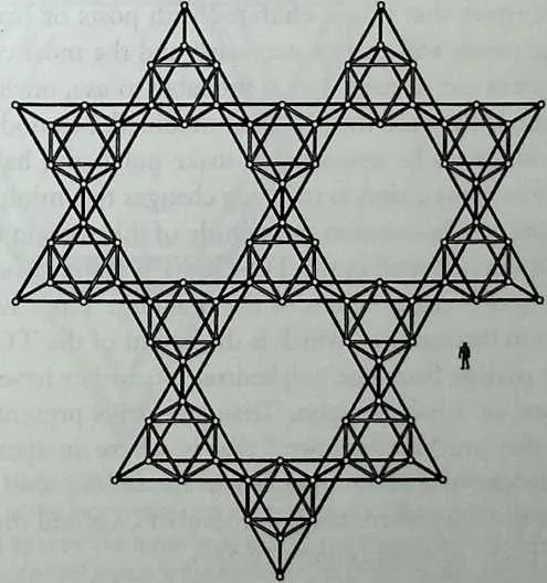
227 Figure 16.56 On this plan, located directly above that of Figure 16.55, we find the median story of three TOs. No structural member is allowed inside. The space frame surrounding the TOs belongs to the upper level of three ‘‘straight-side-up’’ TTs and to the lower level of three ‘‘upside-down’’ TTs. This story does not carry any COs. (Source: J. F. Gabriel, ‘‘Polyhedra in Architecture," International Journal of Space Structures (Special Issue on Morphology and Architecture), H. Lalvani, ed., 1996, Fig. 2. Reprinted with permission of Multi-Science Publishing, Brentwood, UK.)
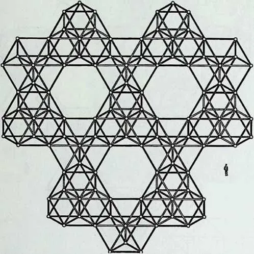
229 Figure 16.57 This story, directly above that of Figure 16.56, repeats the pattern shown in Figure 16.54, three stories below, and would appear again three stories above. Although identical, repeating patterns such as these are not superimposed: It is only every ninth story that identical patterns share vertical projections.
230 UNADULTERATED POLYHEDRA
231 The problem is different if the structural system used to build the TO-CO-TT matrix is not a space frame. Consider a monolithic structure of the shell or folded-plate type, such as shown in Figure 16.52. There, presumably, the space within all the TOs, all the COs, and all the TTs could theoretically be wide open, that is, not cluttered with posts or braces. As in any building, smaller rooms will also be necessary, and the most coherent means to make small spaces out of large ones is probably to use, once again, octahe-dra and tetrahedra, and to use them in their modified, hexmod version. Some modifications will always be necessary to make polyhedra habitable but my main effort, here as always, aims at reducing changes to a minimum. Thus the choice of the word unadulterated in the subtitle of this section (Figure 16.58).
232 Large rooms can be found in the TO-CO-TT matrix whenever they are required by the functional program of the building. Their height will normally be limited to three stories, which is the height of the TO. Observe that bays permitting passage from one polyhedron to another have the shape of a triangle, a square, or a half-hexagon. Triangular bays present an occasional obstacle where they are ‘‘upside-down,’’ that is, where an apex is at the floor level and the opposite base of the triangle is at the ceiling level. This situation is only found on the story where the lower level of COs and the upper level of upside-down TTs are adjacent (Figure 16.58£).
233 Because the conditions of habitability within unadulterated polyhedra cannot all be reviewed
together, we will look at all basic spaces separately. We already know that the TO is a
three-story volume and the TT and the CO are two-story volumes. In the infinite structure of
which these polyhedra are the modules, only the TT is found in two different positions, that is,
either resting on a hexagon or resting on a triangle. Depending on their relative position,
the
four spaces within are totally dissimilar. Consequently, it is a series of nine spaces altogether,
each with its own distinct shape, that we must examine.
234 The three-dimensional relationship between the polyhedra obeys rigorous rules. Hexagonal faces always separate—and also unite, for that matter—TOs and TTs. Triangles are always shared by COs and TTs. Finally, squares connect COs to TOs. A vertical sequence will then always consist of a CO, a
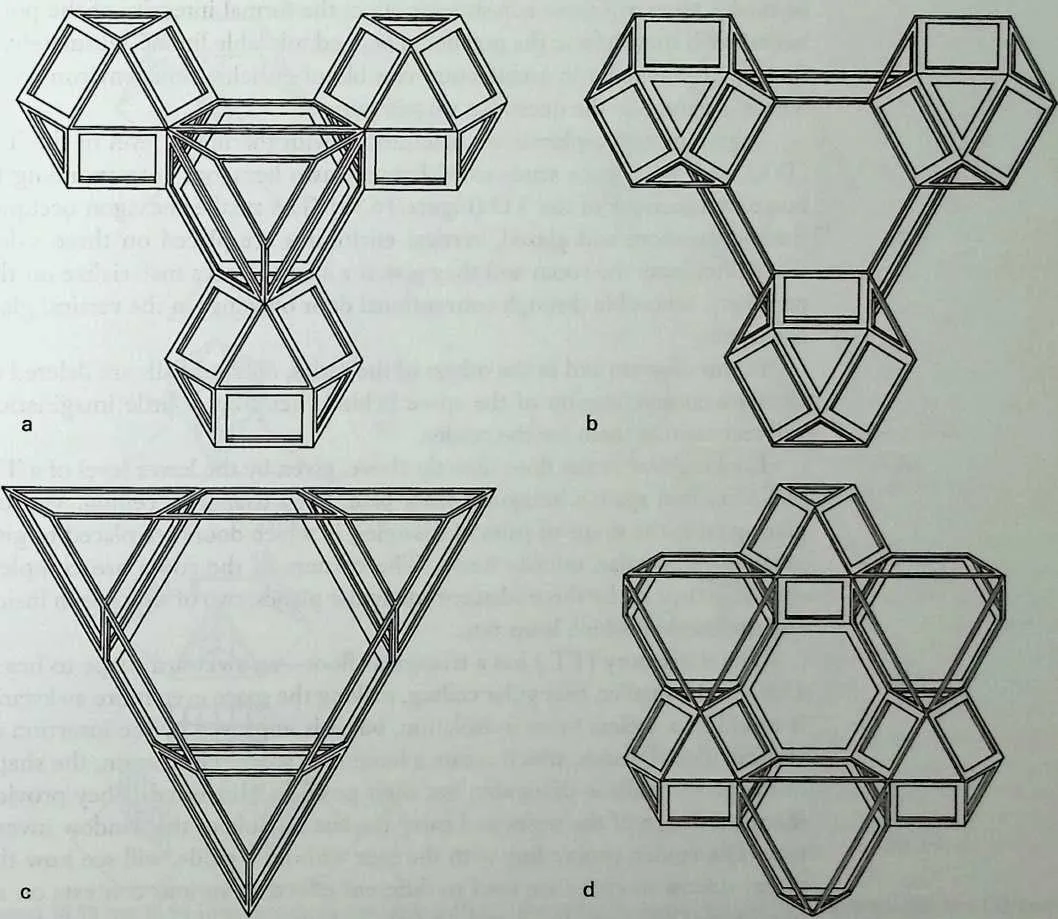
236 Figure 16.58 The nature of the spaces within is shown in a selection of four horizontal sections, one above the other. Beginning with the first of the four stories, the lower level of a TO occupies the center of the cluster (d). Surrounding it are two sets of alternating spaces: the lower level of a TT and the upper level of a CO, each repeated three times. On the story directly above, the central space is the median level of the TO, surrounded by the upper level of aTT, repeated three times (c). The spaces that would be found above the COs of the story below are deleted. The reader is invited to identify them and, in the process, become familiar with the complete three-dimensional pattern. The third story, with the upper level of the TO at the center, is surrounded by the lower level of another set of COs (b). Here again, three peripheral spaces are missing: What are they? On the fourth story, last of the sequence, the lower level of aTT is at the center of the cluster (a). The upper level of three COs is shown around it What are the spaces that would nestle in the interstices? As a reminder that spaces can be higher than one story, floors are deleted from all the drawings. In (a)the upper level of the TT is shown as well as the lower level. (Source: J. F. Gabriel, ‘‘The Architectural Potential of Polyhedra,’’ in Space Structures, G. A. R. Parke and C. M. Howard, eds., Thomas Telford, London, 1993, pp. 2025–2032, Figs. 2,3. Reprinted with permission.)
238239TT, a TO, and another TT, after which this order is repeated again. Only the TT appears twice in the sequence, because of its inverted position in space (Figure 16.53).
240As stated previously, there are nine basic spaces in the matrix. Before we set out to visit them, I would like to clarify my point of view once again: It is that of an architect in search of the essential conditions of habitability. What are these conditions? They consist of enclosures, horizontal floors, doors, and windows. Do our polyhedra meet these conditions? What adjustments must be made? How will these adjustments affect the formal integrity of the poly-hedra? Will they deform the polyhedra beyond tolerable limits? Ultimately, is the use of polyhedra in architecture capable of enriching our environment? Those are some of the questions we will pursue.
241Beginning our exploration—arbitrarily—with the upper level of the TO (TOU), we find a space sandwiched between two hexagons corresponding to horizontal sections of the TO (Figure 16.59). The smaller hexagon occupies the top position, and glazed, vertical enclosures are placed on three sides. They illuminate the room and they give it a shape. Decks materialize on the periphery, accessible through conventional door openings in the vertical glass enclosures.
242In this diagram and in the others of the series, oblique walls are deleted to facilitate comprehension of the space behind them, but a little imagination will reconstitute them for the reader.
243Looking now at the floor directly above, given by the lower level of a TT (TTi), we find again a hexagonal floor plan, but a triangular ceiling. Vertical glazing takes the shape of pairs of triangles, in which doors are placed to give access to triangular, outside decks. The corners of the room are complex, shaped as they are by three adjacent triangular planes, two of which lean inside and the other of which leans out.
244The third story (TTU) has a triangular floor—an awkward shape to begin with—and a smaller, triangular ceiling, making the space even more awkward. It would be a useless room in isolation, but it is improved by the insertion of vertical, glazed planes, which create a hexagonal space. Here again, the shape of the glazed walls is triangular, but their position is inverted. They provide the third design of the series and carry the last module of the window inventory. The reader, proceeding with the tour without a guide, will see how the three window modules are used to different effects in various contexts on all nine stories (Figures 16.59 and 16.60). The shape of the next story (COi) appears to be even more awkward and wasteful than the third one, but in context, it plays an important role as a space connecting others (Figure 16.61a).
245What led me to this particular design of glazed walls? In part, the necessity to draw something: If I am to make a case for architectural polyhedra, I must be able to represent them. To do so, a basic formal vocabulary must be chosen. In addition to the needs already mentioned for enclosures and openings, doors and windows, two considerations influenced the design of the glazed walls. One was the desire to accommodate conventional doors, which can only be done with vertical walls. The other was a wish to respect the for-
246 mal integrity of polyhedral forms, and this led to glazed walls, which, except in one case, do not project outside the faces of polyhedra. If this rule had not been observed, the polyhedra would have been transformed into monsters. After all, polyhedra do not exist simply for the enjoyment of architects. If they are to become building forms, the process of adaptation should be handled with sensitivity. In other words, my goals were truthfulness, simplicity, and consistency. The search for a personal style was not a consideration.
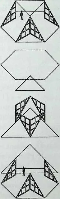

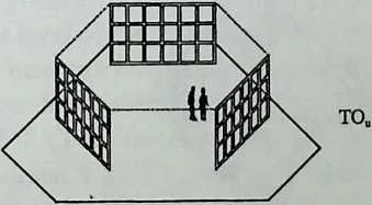
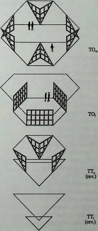
248 coo
249 CO!
250 Figures 16.59 and 16.60 There are three stories in a TO and therefore three distinct spaces. There are two in a CO, two in a TT, and another two in an ‘‘upside-down’’ TT. Going down, for instance, from the upper level of a CO (Figure 16.59, top), we can examine all nine different spaces in a sequential order that never varies. After reaching TO,, at the bottom of Figure 16.59, we continue the visit with T0ra, at the top of Figure 16.60. The last space of the complete series is TT, (reversed), at the bottom of Figure 16.60, but the sequence can be repeated, starting with C0u, which would be found directly under TTt (reversed) already seen at the top of Figure 16.59. It is unlikely that any of these spaces would be freestanding, but looking at them in isolation is a good preliminary to understanding them when grouped in clusters. Vertical glazing replaces certain faces of the polyhedra, and conventional doors can be installed. The complete inventory of glazed, modular parts consists of a total of three designs. (Source: J. F. Gabriel, ‘‘Polyhedra: Skin and Structure,’’ Application of Structural Morphology to Architecture, Proceedings of the Second International Seminar on Structural Morphology, R. Holler, J. Hennicke, and F. Klenk, eds., 1994, pp. 37–46, Figs. 3,4. Reprinted with permission of Institute for Lightweight Structures, University of Stuttgart.)
252253The formal vocabulary used here is not the only possible one. Far from it. The imaginative reader will quickly discover many other design possibilities and derive a great deal of satisfaction from trying them out. A wealth of design possibilities is one important aspect of the field and perhaps the least understood of all.
254Having looked individually at the nine basic spaces found in a vertical sequence, we are now ready to look at them in context (Figure 16.61). As a consequence of the threefold symmetry that rules the pattern, each basic space is surrounded by six others, divided into two sets of three. For instance, the upper level of a CO is adjacent to the lower level of three TTs, alternating with the lower level of three TOs (Figure 16.61a). The TTs are shown, but
255 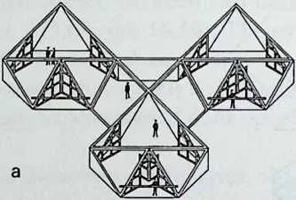
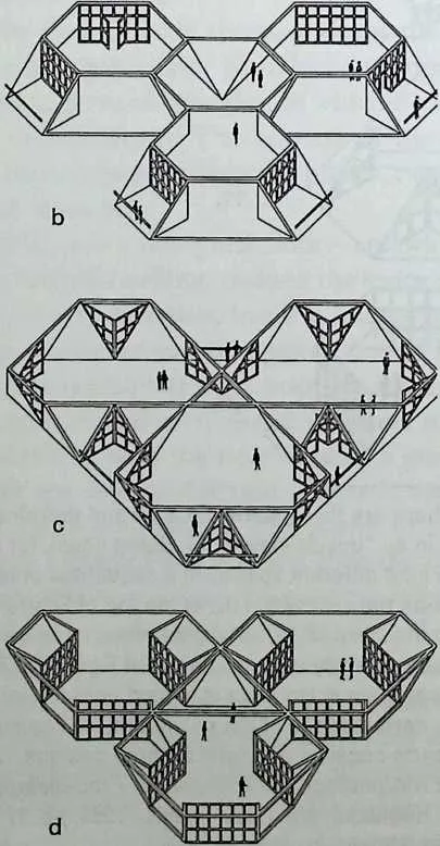 Figure 16.61 Instead of being isolated, some basic spaces are now shown in clusters.
We see here four of the nine stories that form a complete cycle. In (a)the upper level of a CO
(COJ is surrounded by the lower level of a TT (TT|) repeated three times. The lower level of
three TOs would nestle in the intervals. On the story directly below /&),the lower level of
the CO (CO,) is surrounded by the upper level of three TOs (TOJ. The intervals
would receive the upper level of three upside-down TTs (TT„, reversed). Below the CO
at the core, we find the upper level of a TT (TTJ in (c). The reader is invited to
identify the three adjacent spaces that are drawn, as well as the three that would fit in
between. Finally, in (d),the reader should be able to identify all the spaces found on
this level, whether they are entirely drawn or implied. The faces that would affect
the legibility of the interior spaces are deleted in these drawings. All the ‘‘edges,’’
however, are retained. (Source: J. F. Gabriel, ‘‘Habitability Studies of Certain Polyhedra,’’
Spatial Structures: Heritage, Present and Future, Proceedings of the IASS International
Symposium, Milan, 1995, G. C. Giuliani, ed„ Vol. 1, 1995, pp. 165–170, Figs. 2,3, 4,5.
Reprinted with permission of SGEditoriali, Padova, Italy.) the TOs are not. For a
more thorough representation of our spaces, a rotation of 60° has been implemented
between the series shown in Figures 16.59 and 16.60 and the series shown in Figure
16.61.
Figure 16.61 Instead of being isolated, some basic spaces are now shown in clusters.
We see here four of the nine stories that form a complete cycle. In (a)the upper level of a CO
(COJ is surrounded by the lower level of a TT (TT|) repeated three times. The lower level of
three TOs would nestle in the intervals. On the story directly below /&),the lower level of
the CO (CO,) is surrounded by the upper level of three TOs (TOJ. The intervals
would receive the upper level of three upside-down TTs (TT„, reversed). Below the CO
at the core, we find the upper level of a TT (TTJ in (c). The reader is invited to
identify the three adjacent spaces that are drawn, as well as the three that would fit in
between. Finally, in (d),the reader should be able to identify all the spaces found on
this level, whether they are entirely drawn or implied. The faces that would affect
the legibility of the interior spaces are deleted in these drawings. All the ‘‘edges,’’
however, are retained. (Source: J. F. Gabriel, ‘‘Habitability Studies of Certain Polyhedra,’’
Spatial Structures: Heritage, Present and Future, Proceedings of the IASS International
Symposium, Milan, 1995, G. C. Giuliani, ed„ Vol. 1, 1995, pp. 165–170, Figs. 2,3, 4,5.
Reprinted with permission of SGEditoriali, Padova, Italy.) the TOs are not. For a
more thorough representation of our spaces, a rotation of 60° has been implemented
between the series shown in Figures 16.59 and 16.60 and the series shown in Figure
16.61.
257258Polyhedral spaces are fundamentally changed when placed at the core of a cluster and opening onto adjacent polyhedra. The differences can be observed when comparing, for instance, the TT, at the center of Figure 16.61J with the same space shown by itself in Figure 16.59. Portions of the faces that have been replaced with glazing in one case are kept solid in the other. Rectangular bays now appear where a complex assemblage of triangular planes existed. Beyond observations like these, an adequate description of the spaces and of the transformations that occur is difficult and probably pointless.
259The reader should keep in mind that these are only diagrams, not complete designs. It might not be necessary to eliminate an entire face to create a passage between adjacent polyhedra. It will be observed that all edges are retained on all floors. What edge refers to here is a structural member placed where two or three polyhedral faces would intersect. Also note that in Figure 16.61 additional vertical planes close the gaps between vertical and oblique enclosures.
260Of the nine stories forming a complete sequence, four are shown in Figure 16.61. These four stories include seven of the nine basic spaces. As I already mentioned, one of them appears in relation to two sets of polyhedra: It is TTb shown once surrounded by three TOs (Figure 16.61d) and again when its turn comes to cluster around a CO (Figure 16.61a).
261The next two series of diagrams include all the polyhedra that can be clustered around another one at the core (Figures 16.62 and 16.63). The three stories, represented once in axonometric views and once in plan views, are those that would have had a TO on center, but for which stairs and elevators have been substituted. Elevator shafts take over the structural role that the TO would have played. Stairs and elevator shafts belong to the public zone, at the core of the building, whereas the more private spaces are found in the peripheral polyhedra. They are distributed as follows: On the lower story, that is, at the first level of the truncated octahedron (TOi), a TTj alternates with a COU. On the next story, which corresponds with the median level of the TO (TOm), the upper level of the TT (TTU) alternates with the lower level of an upsidedown TT (TTi, reversed). On the third story (TOU), the upper level of the upside-down TT (TTU, reversed) alternates with the lower level of a CO (COi).
262Further horizontal subdivision may be necessary, depending on the programmatic needs of the building. This can be done by means of vertical planes disposed on a hexagonal grid. The reader will recognize the hexmod system in this approach, for the form and the location of the dividers are consistent with the octahedra that implicitly ‘‘fill’’ the larger polyhedra. The vertical elements may also contribute added rigidity and support to the whole structure.
263Readers who still question the title of this section, Unadulterated Polyhedra, are begged to remember that polyhedra must be modified to some degree when we use them in the design of buildings. Nor should this be regretted because polyhedra are pure abstractions—concepts of the mind—whereas construction is a physical reality. Polyhedra should be modified and lose some
264 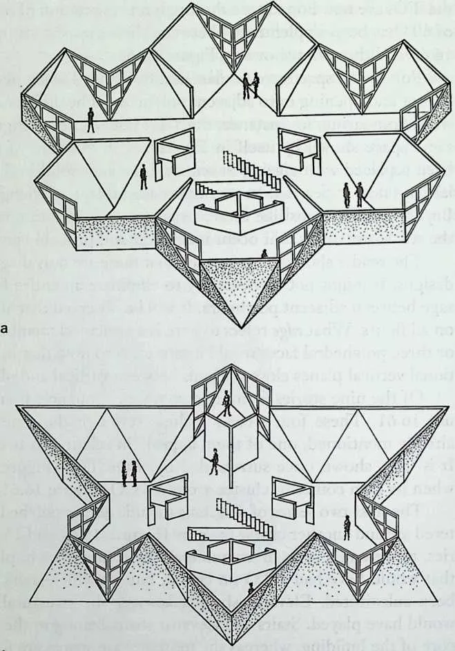
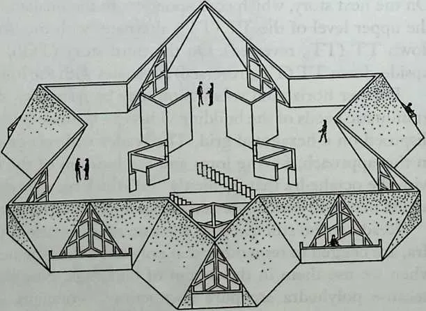 Figure 16.62 Three more stories of the cycle, with a TO at the core. All six
polyhedra, or portions thereof, surrounding its three levels are shown. In (a) the lower level of a
CO alternates with the upper level of an upsidedown TT. Stairs and elevator shafts are fitted in
the space conceptually occupied by the TO, whose form is no longer recognizable. The shafts can
accommodate up to six elevators or they can house services; they are drawn shorter than they are
so as not to interfere with our perception of the main spaces. On the story immediately
below (b) which corresponds to the median level of the TO, the lower level of three
upsidedown TTs alternates with the upper level of three straight-side-up TTs. The
reader who makes the effort to identify the spaces shown on the next story (c) will be
rewarded with an understanding of a three-dimensional pattern rich in architectural
possibilities. Whatever the use of the building, its functional organization will probably
require further subdivision of the space within. In (a)the triangular faces shared by
COs and TTs suggest a possible means of subdivision. Another method, shown in
(b) and (c), consists of using vertical dividers derived from the hexmod pattern. In
either case, the dividing elements can also contribute to the structural framework, if
necessary.
Figure 16.62 Three more stories of the cycle, with a TO at the core. All six
polyhedra, or portions thereof, surrounding its three levels are shown. In (a) the lower level of a
CO alternates with the upper level of an upsidedown TT. Stairs and elevator shafts are fitted in
the space conceptually occupied by the TO, whose form is no longer recognizable. The shafts can
accommodate up to six elevators or they can house services; they are drawn shorter than they are
so as not to interfere with our perception of the main spaces. On the story immediately
below (b) which corresponds to the median level of the TO, the lower level of three
upsidedown TTs alternates with the upper level of three straight-side-up TTs. The
reader who makes the effort to identify the spaces shown on the next story (c) will be
rewarded with an understanding of a three-dimensional pattern rich in architectural
possibilities. Whatever the use of the building, its functional organization will probably
require further subdivision of the space within. In (a)the triangular faces shared by
COs and TTs suggest a possible means of subdivision. Another method, shown in
(b) and (c), consists of using vertical dividers derived from the hexmod pattern. In
either case, the dividing elements can also contribute to the structural framework, if
necessary.
265 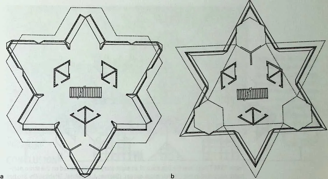
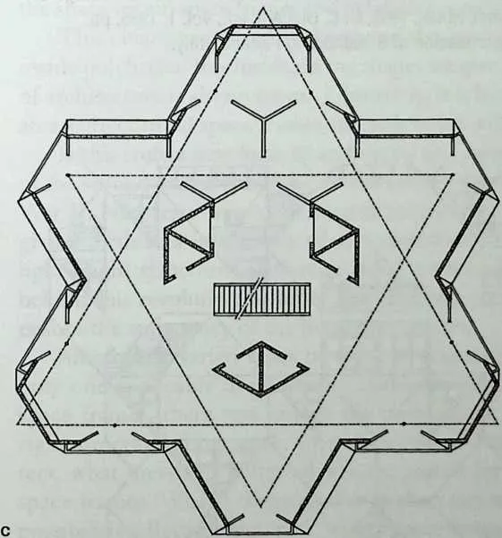 Figure 16.63 These three floor plans match the diagrams of Figure 16.62. The only
variations between the two sets of drawings concern some of the dividers.
Figure 16.63 These three floor plans match the diagrams of Figure 16.62. The only
variations between the two sets of drawings concern some of the dividers.
267268of their geometric perfection in the process of becoming architecture. I chose that title simply because, in the last section of this chapter, my intention was to keep polyhedra and infinite structures as close to their ideal states as possible (Figures 16.64 to 16.66).
269We have seen, on the contrary, that when a three-way, multilayer space frame is transformed into the hexmod system, it undergoes such changes that an observer might find it difficult to recognize the kinship of one with the other.
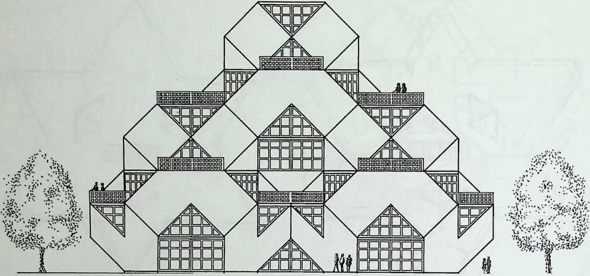
272273Figure 16.64 This is how the elevation of an eight-story building based on the three poly-hedra discussed in this chapter might appear. {Source: J. F. Gabriel, ‘‘Habitability Studies of Certain Polyhedra,’’ Spatial Structures: Heritage, Present and Future, Proceedings of the IASS International Symposium, Milan, 1995, G. C. Giuliani, ed., Vol. 1,1995, pp. 165–170, Fig. 6. Reprinted with permission of SGEditoriali, Padova, Italy.)
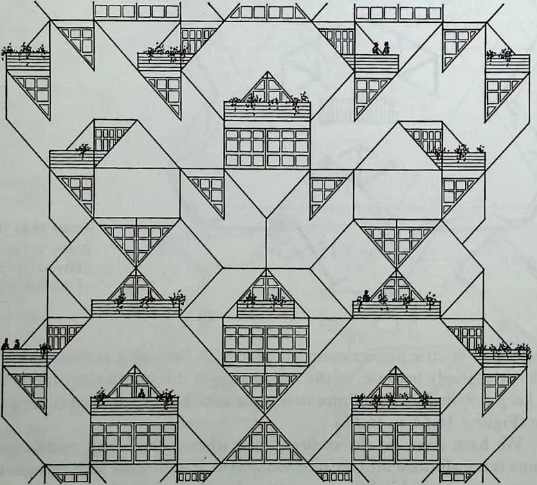
275 Figure 16.65 Shown here in elevation is the complete cycle of all nine possible spatial patterns discussed in this chapter. The three basic polyhedra are arranged in superimposed rings of six, with a seventh one at the core. Although the relationship between the polyhedra is always the same, all nine floor plans are different, as are their spatial characteristics.
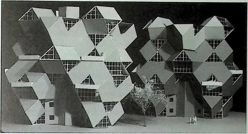
277 Figure 16.66 Models give an idea of the possible appearance of buildings based on an infinite pattern of truncated octahedra, cuboctahedra, and truncated tetrahedra. As in Figure 16.65, the nine stories of the cycle are included.
16.5 CONCLUSION
279I hope this last chapter makes a substantial contribution to the argument that the space within space frames and polyhedra is habitable, versatile, and pleasant.
280 This chapter is placed at the end of the book because in it we take a look inside polyhedra. It is inside, in the shapes we give our rooms, that the essence of architecture is always found: Ultimately, it is by the quality of its spaces that an architecture of space frames and polyhedra will be judged.
281 Is this truly a new form of architecture? The major structural innovations of the second half of the 20th century occurred in the decade following World War II. New ways were then devised to span larger spaces with less material, giving birth to a new family of structural systems called space structures, or lightweight structures. Although economy was certainly a motivating force behind this revolution, a loftier way of looking at it is as one more effort to ensure the supremacy of the mind over matter.
282 Among the varied types of space structures, the space frame is still the only one applicable in multistory buildings. At the origin of my interest in space frames, there was indeed the recognition that a tetrahedron made a rigid structural framework, whereas a cube did not. Because I am an architect, what inevitably followed was the search for architectural space within space frames. What I discovered over the years were countless architectural possibilities. Because the space within space frames yields all sorts of perfectly habitable shapes, it seems to me that space frames should be more commonly employed in multistory buildings than conventional post-and-beam, or post-and-slab, systems.
283 Octahedra and tetrahedra, being the basic structural units of a space frame, can be used as ‘‘building blocks.’’ They can also be used at the conceptual level to generate other, larger, polyhedral forms and spaces, the construction of which would rely not on steel but on different materials—reinforced concrete most likely—and different structural principles, such as shells or folded plates.
284 Polyhedra that have more faces than the cube have a better ratio between the area of their envelope and their volume than the cube. These polyhedra would presumably use less material to build and suffer less heat loss than a cubic box. Motivations like these are valid, but there are others, just as legitimate. The intrinsic beauty of polyhedra is one. The visual and spatial order of infinite structures is another. The necessity to simply explore new avenues is yet another.
285 While I was engaged in my voyage of discovery among polyhedra, fashion in architecture tended more and more to turn its back on logic, clarity, and order. Imagination, is of course, crucial in architectural design and fantasy is by no means unwelcome, but, in the last few decades, arbitrary new building forms have been sprouting at an alarming rate. The license to do anything that fancy suggests can result in aberrations and, eventually, chaos. I hope the time has come for a turnaround. Design is the search for order, not irresponsible self-expression. A structuralist approach, combined with the discipline of geometry, would provide a renewed logic and a sound philosophical basis for architectural design. The application of a consistent formal language, with its many rules and restrictions, has never inhibited creativity. On the contrary, it always liberates it.
286 In this chapter I have tried to show the architectural potential of a limited number of configurations derived from the 12-connected network. There are many more configurations, waiting to be discovered by the curious mind, that could be applied in the design of buildings by imaginative architects and engineers. I believe that infinite structures—space frames and polyhedra—could be the means toward a sensible and dynamic architecture, one that could contribute to the visual and spatial expression of an organized and democratic society. As one would drive or walk around one of these structures, its appearance would slowly change, but always return to the reassurance of symmetry. Inside, one would experience a variety of spaces, some of them unexpected, but all devoid of the unbearable boredom of the modern bare box effect.
16.6 NOTES
- 1.
- A. Holden, Shapes, Space, and Symmetry, Columbia University Press, 1971.
- 2.
- J. F. Gabriel, ‘‘Three-Dimensional Suburbs,’’ Proceedings of the IASS World Congress on Space Enclosures, Montreal, 1916, Building Research Centre, Concordia University.
- 3.
- J. F. Gabriel, ‘‘Living in a Space Frame,’’ Proceedings of the Second International Conference on Space Structures, University of Surrey, Guildford, 1975.
- 4.
- J. F. Gabriel and J. A. Mandel, ‘‘A Space Frame Building System for Housing,’’ Proceedings of the Third International Conference on Space Structures, University of Surrey, Guildford, 1984, Elsevier, London, 1984.
- 5.
- David P. Billington, The Tower and the Bridge, The New Art of Engineering, Basic Books, New York, 1983.
- 6.
- The Architectural Forum, Jan. 1938, p. 68.
- 7.
- J. F. Gabriel, ‘‘Metamorphic Architecture and Space Towns,’’ Proceedings of the IASS International Conference, Alma-Ata, 1977.
- 8.
- J. Dahinden, Urban Structures for the Future, Pall Mall Press, London, 1972.
- 9.
- J. F. Gabriel, ‘‘Megapolyhedra, Spatial Structures at the Turn of the Millennium, Vol. H, Structural Form,’’ Proceedings of the IASS Symposium, Copenhagen, 1991.
- 10.
- J. F. Gabriel, ‘‘Skyscrapers or Spacetowns, Developments in Structural Engineering,’’ Proceedings of the Forth Rail Bridge Centenary Conference, Edinburgh, 1990.
- 11.
- J. E Gabriel, ‘‘Polyhedra in Architecture,’’ Proceedings of the International Conference on the Design and Construction ofNon-Conventional Structures, London, 1981.
- 12.
- J. F. Gabriel, ‘‘Infinite Structures in Architecture,’’ Proceedings of the First International Seminar on Structural Morphology, Montpellier, France, 1992. Reprinted in the IASS Bulletin, Vol. 34, No. 3, 1993.
- 13.
- C. Dumitrescu, Arhitectura Formelor Poliedrate, Bucharest, 1993.
- 14.
- J. F. Gabriel, ‘‘Clusters of Polyhedra in Architecture,’’ International Journal of Space Structures (Special Issue on Morphology and Architecture), 1996.
16.7 BIBLIOGRAPHY
290Baldwin, J.: Bucky Works, Buckminster Fuller’s Ideas for Today, Wiley, New York, 1996.
291 Banham, R.: ‘‘A Clip-on Architecture,’’ Design Quarterly, Vol. 63, 1965.
292 Borrego, J.: Space Grid Structures, MIT Press, Cambridge, MA, 1968.
293 Bragdon, C.: The Beautiful Necessity, A Quest Book, 1978.
294 Burt, M.: ‘‘Periodic Hyperbolic Surfaces as Modular Membrane Structures,’’ International Symposium, Weitgespannte Flachentragwerke, University of Stuttgart, 1985.
295 Burt, M.: ‘‘Low Density I.P.L. Space Frames for Wide-Span and High Rise Structures,’’ IASS International Conference, Madrid, 1989.
296 Burt, M.: The Periodic Table of the Polyhedral Universe, Technion, Israel Institute of Technology, Haifa, 1996.
297 Condit, C.: ‘‘The Wind Bracing of Buildings,’’ Scientific American, Vol. 230; No. 2, 1974.
298 Cook, P.: Architecture: Action and Plan, Reinhold/Studio Vista, 1967.
299 Crapo, H.: ‘‘The Tetrahedral-Octahedral Truss,’’ Structural Topology, No. 8, 1983.
300 Critchlow, K.: Order in Space, Viking, New York, 1965.
301 Crosbie, M.: ‘‘Desert Shield,’’ Architecture, May 1991.
302 Dixon, J. M.: ‘‘Campus City Continued,’’ The Architectural Forum, Vol. 129, No. 5,1968.
303 Du Chateau, S.: Structures Spatiales, Brussels, 1967.
304 Du Chateau, S.: ‘‘Structures spatiales, Phenomene d’Ideation en Architecture,’’ Third International Conference on Space Structures, University of Surrey, 1984, Elsevier.
305 Edmondson, A.: A Fuller Explanation, The Synergetic Geometry ofR Buckminster Fuller, Van Nostrand Reinhold, New York, 1992.
306 Eekhout, M.: Architecture in Space Structures, Vitgeverij Olo, Rotterdam, 1989.
307 Emmerich, D. G.: Exercices de Geometric Constructive, Travaux d’Etudiants, Ecole Nationale Superieure des Beaux-Arts, Paris, 1970.
308 Friedman, Y: Une utopie realisee, Catalogue de 1’Exposition, Musee d’Art Modeme de la Ville de Paris, 1975.
309 Friedman, Y.: ‘‘Space Frames and Span-Over Buildings,’’ International Journal of Space Structures, Vol. 6, No. 4, 1991.
310 Fuller, R. B.: ‘‘Conceptuality of Fundamental Structures,’’ in G. Kepes, ed., Structure in Art and in Science, Braziller, New York, 1965.
311 Fuller, R. B.: ‘‘Design Science-Engineering, an Economic Success of All Humanity,’’ Zodiac, Vol. 19, 1969.
312 Fuller, R. B., and Marks, R.: The Dymaxion World of Buckminster Fuller, Anchor Books, 1973.
313 Hanaor, A.: ‘‘Prefabricated Spatial Frame Systems,’’ International Journal of Space Structures, Vol. 10, No. 3, 1995.
314 Ishii, K., ed.: Membrane Structures in Japan, SPS Publishing, Tokyo, 1996.
315 Kappraff, J.: ‘‘A Course in the Mathematics of Design,’’ Structural Topology, No. 8, 1983.
316 Kihlstedt, F. T: ‘‘The Crystal Palace,’’ Scientific American, Vol. 251, No. 4, 1984.
317 Kuhn, W: ‘‘Cubic Structures with Elements Obtained by the Concretization of Geometrical Reticulations,’’ Zodiac, Vol. 19, 1969.
318 Lalvani, H.: Transpolyhedra, Dual Transformations by Explosion-Implosion, New York, 1977.
319 Lalvani, H.: ‘‘Spatial Concepts for Non-Periodic Architecture, A Selection from 8 Patents Focusing on Non-Periodic Geometries for a New Generation of Architectural Space Structures and Space-Defining Systems,’’ 1991.
320 Lalvani, H., and Collins, T: ‘‘Comparative Morphology of Configurations with Reduced Part Count Derived from the Octahedral-Tetrahedral Truss,’’ NASA Technical Memorandum 102768, 1991.
321 Le Ricolais, R.: Interviews with Le Ricolais, Structures Implicit and Explicit, Graduate School of Fine Arts, University of Pennsylvania, Philadelphia, 1973.
322 Makowski, Z. S.: ‘‘Space Structures of Today and Tomorrow,’’ Proceedings of the Third International Conference on Space Structures, University of Surrey, 1984.
323 Makowski, Z. S.: ‘‘New trends in Spatial Structures,’’ Bulletin of the International Association for Shell and Spatial Structures, Vol. 27, No. 1, 1986.
324 Makowski, Z. S.: ‘‘Space Structures—A Review of the Developments Within the Last Decade,’’ Space Structures, 1993.
325 Medwadowski, S. J.: ‘‘Space Frames and Architecture,’’ Bulletin of the International Association for Shell and Spatial Structures, Vol. 14, No. 3, 1983.
326 Mengeringhausen, M.: Komposition i?n Raum, Wurzburg, 1983.
327 Nervi, P. L.: ‘‘Is Architecture Moving Toward Unchangeable Forms?’’ Structure in Art and in Science, G. Kepes, ed., Braziller, New York, 1965.
328 Neumann, A.: ‘‘Architecture as Ornament,’’ Zodiac, Vol. 19, 1969.
329 Pauling, L.: The Nature of the Chemical Bond, Cornell University Press, 1939.
330 Pearce, P.: Structure in Nature Is a Strategy for Design, MIT Press, Cambridge, MA.
331 Popko, E.: Geodesics, University of Detroit Press, 1968.
332 Rebielak, J.: ‘‘Space Structures—Proposal for Shaping,’’ International Journal of Space Structures, Vol. 7, No. 3, 1992.
333 Safdie, M.: ‘‘New Environmental Requirements for Urban Building,’’ Zodiac, Vol. 19, 1969.
334 Salvadori, M.: Why Buildings Stand Up, W. W. Norton, 1980.
335 Samuely, F. J.: ‘‘Space Frame Defined,’’ Architectural Forum, Feb. 1953.
336 Satterwhite, R. G.: ‘‘A Space-Frame as a Home,’’ International Journal of Space Structures, Vol. 6, No. 4, 1991.
337 Sloane, N.J. A.: ‘‘The Packing of Spheres,’’ Scientific American, Vol. 250, No. 1, 1984.
338 Stewart, D.: ‘‘Skyscraping,’’ Discover, Vol. 1, No. 9, 1988.
339 Stuart, D. R.: ‘‘Space-Filling Ortho-Surfaces and Their Duals,’’ International Journal of Space Structures, Vol. 6, No. 4, 1991.
340 Thompson, D. W.: On Growth and Form, Cambridge University Press, 1969.
341 Tbrroja, E.: The Structures of Eduardo Torroja, F. W. Dodge Corporation, New York, 1958.
342 Tucker, J. B.: ‘‘Superskyscrapers: Aiming for 200 Stories,’’ High Technology, Vol. 5, No. 1, 1985.
343 Tyng, A. G.: ‘‘Synthesis of a Traditional House with a Space-Frame,’’ International Journal of Space Structures, Vol. 6, No. 4, 1991.
344 Wachsmann, K: The Turning Point of Building, Reinhold, 1961.
346 IRENE E. AYAD was bom in Germany and partially raised in England, where she completed her secondary education. After a brief stay in Egypt, she came to the United States, where she studied art history at Empire State College in Buffalo, New York While an undergraduate student there, she was also a regular contributor to a broadcast program on cultural affairs. The program was offered weekly by an affiliate station of National Public Radio and focused on art, architecture, and urban issues. This gave Irene Ayad the impetus for earning her graduate degree in urban planning at the State University of New York at Buffalo. It is there that she became interested in the work of Louis Kahn and went on to pursue further graduate studies at Cornell University. She received her Ph.D. in architectural and urban history with a thesis on Louis Kahn.
347 Dr. Ayad has taught at Cornell University, the University of Tennessee at Knoxville, and Roger Williams University. She is currently working on a book about Louis Kahn’s neighborhood and housing projects.
348 LAWRENCE DAVIS, a registered architect, grew up in the Midwest and earned a Bachelor of Architecture degree (magna cum laude) from the University of Cincinnati, and a master’s degree from Columbia University, New York. He studied under Kenneth Frampton and Steven Holl, and he was teaching assistant and occasional employee of the latter. He worked for three years in the office of James Stewart Polshek and Partners, most notably on the Yerba Buena Theater in San Francisco. He opened his own practice in Cincinnati in 1991, at the same time teaching and pursuing his research interests.
349 Since 1994, Lawrence Davis has been an assistant professor at the Syracuse University School of Architecture, New York, where he teaches architectural design and the history and theory of the suburban environment in America.
350 J. FRANCOIS GABRIEL was bom and raised in Paris where he studied art and architecture. He received a classical training at the Ecole des Beaux-Arts and practiced architecture in Paris and the United States. While a student he was invited by Le Corbusier to join CIAMZAscoral.
351 For many years, J. Francois Gabriel has investigated the architectural potential of space frames and advocated their use. He has published and lectured on the subject in many countries. He belongs to the International Association for Shell and Spatial Structures (IASS) and is co-founder of its Structural Morphology Working Group. He is also a member of the editorial board of the International Journal of Space Structures.
352 J. Francois Gabriel has taught at several universities, including the Massachusetts Institute of Technology and Syracuse University, New York, where he currently teaches courses on the design of classical buildings, space structures, and the architecture of space frames.
353 ARIEL HANAOR earned a Bachelor of Science degree and a master’s degree in civil engineering from the Technion in Haifa. In 1980, he received a Doctorate of Philosophy in civil engineering from the University of Melbourne, Australia. He worked as a consulting engineer in Israel from 1965 to 1972, and in Australia from 1973 to 1979.
354 His doctoral research at the University of Melbourne focused on space trusses, and he did postdoctoral research at the Imperial College in London on concrete technology, and at Rutgers University in New Jersey on structural analysis, space structures, tensegrity systems, and concrete technology. Since 1980, he has been a senior research fellow at the National Building Research Institute, the Technion, working primarily on steel structures.
355 Dr. Hanaor is a member of the International Association for Shell and Spatial Structures (IASS), and of the editorial board of the International Journal of Space Structures.
356 PIETER HUYBERS was bom in the Netherlands and studied architecture at the Faculty of Building Engineering of the Technical University of Delft. He received a doctorate degree in 1972.
357 He worked in an architectural office and his designs were built in the Netherlands, Mali, and England. In research, he concentrates on the potential of construction materials such as GRP, cardboard, plastics, membranes, thin roundwood, and on the potential of polyhedra in building. He is the head of a research group on building technology at the Civil Engineering Faculty of Delft University.
358 Dr. Huybers is a member of the International Association for Shell and Spatial Structures (IASS) and one of the founding members of the IASS working group on structural morphology.
359 HARESH LALVANI is a professor of architecture at the Pratt Institute and Design Scientistin-Residence at the Cathedral of St. John the Divine in New York.
360 He has been involved with morphological research for nearly three decades and has exhibited and published widely, presenting his work at leading forums on art, morphology, architecture, engineering, mathematics, space structures, and computer graphics. He has authored two books, Transpolyhedra in 1977 and Structures on Hyper-Structures in 1982.
361 He contributed to the 1988 U.S. government report on research strategy for computer-aided productivity and, between 1989 and 1990, he spent a sabbatical year at the NASA-Langley Research Center, Hampton, Virginia. He was curator of the Buckminster Fuller Centennial Exhibition Contemporary Developments in Design Science, which opened at the Cathedral of St. John the Divine in 1995, continued at the Pratt Institute, and moved to Mimar Sinan University in conjunction with the United Nations’s Habitat II Conference, held in Istanbul in 1996.
362 Professor Lalvani received grants from the Graham Foundation for Advanced Studies in the Fine Arts, the National Endowment for the Arts, and the National Institute for Architectural Education. He is affiliated with the International Society for the Interdisciplinary Study of Symmetry (ISIS), the Japan Institute for Hyper-Space Science, and the Structural Morphology Working Group, and he serves on the editorial boards of the International Journal of Space Structures and Structural Topology. He is the guest editor of the special issue of Space Structures on Morphology and Architecture.
363 MATTHYS LEVY was bom in Switzerland and graduated from the City College of New York. He earned a Master’s of Science degree and a civil engineering degree from Columbia University.
364 He was the principal designer of the Javits Exhibition and Conference Center in New York, the Georgia Dome in Atlanta, the Banque Lambert building in Brussels, among many other buildings, for example, in Boston, London, and Korea.
365 Matthys Levy taught at Columbia University and the Pratt Institute in New York and has lectured at universities around the world. In addition to numerous professional publications on structures, computer analysis, aesthetics, and building systems design, he is co-author of the books Why Buildings Fall Down, Structural Design in Architecture, and Why the Earth Quakes. He is a member of the National Academy of Engineering and many professional societies, and he has served as director of several corporations. He is the recipient of many awards, including the American Society of Civil Engineers (ASCE) Innovation in Civil Engineering Award and the IASS Tsuboi Award.
366 He is the inventor of the Tenstar Dome structure, a tensegrity dome used to cover large spaces.
367 ARTHUR L. LOEB was bom in Amsterdam, where he received his primary and secondary education. He earned a Bachelor of Science degree in chemistry from the University of Pennsylvania, and a master’s degree in physics and a Doctorate of Philosophy in chemical physics from Harvard University.
368 Arthur Loeb’s publications include Introduction to Wave Mechanics, with Louis Harris (McGraw-Hill), Color and Symmetry (Wiley/Krieger), Space Structures (Addison-Wesley/Birkhaiiser), Concepts and Images (Birkhaiiser), and contributions to Gyorgy Kepes’s Vision and Value series, Buckminster Fuller’s Synergetics, Hargittai’s Symmetry, and Clifford Pickover’s Future of Fractals. His articles have been published in Acta Crystallo-graphica, Leonardo, International Journal of Space Structures, Physical Review, and other periodicals.
369 He is the editor of the Design Science Collection for Birkhaiiser, vice-president of the International Society for the Interdisciplinary Study of Symmetry, member of the Advisory Board of the Buckminster Fuller Institute, and a life fellow of the American Institute of Chemistry and the Royal Society of Arts of London.
370 Professor Loeb is also an artist and a professional singer. He is the founder of the Collegium losquinum in Boston.
371 A former Master and Honorary Associate of Dudley House at Harvard University, he is currently a senior lecturer and honorary associate in visual and environmental studies and a member of the faculty of the Graduate School of Education. He teaches design science and visual mathematics.
372 RENE MOTRO is a civil engineer and, since 1983, a doctor of state of the University of Montpellier in France. He has assumed the scientific leadership of two research teams on lightweight structures, one of which is established at the School of Architecture of the University of Montpellier. He is engaged in the study of initially stressed systems applied to tensegrity systems and form-finding of cable nets and membrane structures.
373 Professor Motto’s interest in spatial structures led him to study the geometry of poly-hedra with a view toward geometric optimization. He has become simultaneously involved with the symbolism of polyhedra, a topic on which he has lectured and published a number of studies.
374 A member of the executive council of the International Association for Shell and Spatial Structures (IASS) and co-founder of its working group on structural morphology, in 1992 he organized the First International Seminar on that topic.
375 HOSHYAR NOOSHIN was bom in Tehran and received his first degree in civil engineering from the University of Tehran. He subsequently earned a Ph.D. from the University of London.
376 He is currently a professor of space structures in the Department of Civil Engineering at the University of Surrey, where he is also the director of the Space Structures Research Centre.
377 Professor Nooshin is the chief editor of the International Journal of Space Structures and a fellow of the Institution of Civil Engineers. He is the originator of the concept of formex algebra.
378 ROLLAND RISTINE is an architect who studied under Bruce Goff at the University of Oklahoma.
379 He has worked with several architectural firms in Chicago, then in New York, notably with Edgar Tafel, Conklin and Rossant, Stephen B. Jacobs, and Robert E. Meadows. He has taught courses on the history of architecture at the Manhattan Center of the New York Institute of Technology. His practice, based in Brooklyn, now concentrates on the making of architectural renderings.
380 Rolland Risdne is the editor of Network News, the newsletter of the Friends of Keb-yar, an organization comprising the friends, clients, and former students of Frank Lloyd Wright, Bruce Goff, and their followers.
381 TONY ROBBIN is an artist who lives in New York. He has had over 20 solo exhibitions and participated in 150 group exhibitions in the United States and abroad.
382 He is the author of two books, Fourfield: Computers, Art and the Fourth Dimension, published in 1992 (Bulfinch, Little Brown), and Engineering a New Architecture, published in 1996 (Yale University Press). He was the recipient of grants from the Graham Foundation for Advanced Studies in the Arts, the National Science Foundation, and the National Endowment for the Arts. He has lectured extensively to university audiences and professional organizations of artists, mathematicians, computer scientists, architects, and engineers.
383 For the past 10 years, Tony Robbin has pioneered and advocated the use of quasicrystal geometry in architecture.
384 MASAO SAITOH is a graduate of the Department of Architecture of Nihon University, where he currently is a professor of structural engineering. Active in research on space structures and their applications, he has developed hybrid tension systems such as beam string structures, ‘‘Skelsion,’’ and complex string domes.
385 He contributed to the design of many notable structures, including the Suntory Pavilion at Tsukuba Expo ‘85, the Multi-Sports Complex Amagi Dome, the Iwase Sports Dome, both of 1991, and the Izumo Dome Stadium of 1992. In 1986, he received the Architectural Institute of Japan Award.
386 Professor Saitoh is a member of the executive council of the International Association for Shell and Spatial Structures (IASS) and vice-chairman of its working group on tension structures.
387 JOSTOMLOW is a Dutch engineer who studied architecture at Delft University. Early on, he developed an interest in the structural and mathematical aspects of architecture and he became one of the co-founders of the Gaudf Research Delft Group, directed by Jan Mole-ma. In 1986, he received a doctoral degree from Stuttgart University. His thesis was about Gaudi’s hanging model, which was reconstituted on a large scale by a German-Dutch team.
388 Jos 'Ibmlow was inspired by Frei Otto’s influence to work at the Institute of Lightweight Structures. There, he assisted Rainer Graefe and Ekkehard Ramm in their studies on the history of structural design. This is one area investigated by the research group SFB 230: Natural Structures-Lightweight Structures in Architecture and Nature.
389 Since 1995, Professor Tomlow has been teaching art and architectural history in the Building Department of the Hochschule fur Technik, Wirtschaft und Sozialwesen Zit-tau/Gbrlitz in Germany.
390 TURE WESTER graduated from the Danish Engineering Academy and worked on form-finding and the design of spatial structures with several consulting engineering companies before joining the School of Architecture at the Royal Danish Academy of Fine Arts as a lecturer and research assistant. He is currently associate professor and head of the Laboratory for Plate Structures, which is supported by the Danish Technical Research Foundation and the Danish Ministry of Culture.
391 Structural morphology, structures in nature, force and form language, and the structural behavior and optimal shaping of plate structures are among Tire Wester’s main research topics. He is the originator of the concept of structural duality and the author of Structural Order in Space. He has published numerous research papers in international journals and conference proceedings.
392 Professor Wester is a member of the board of the International Society for the Interdisciplinary Study of Symmetry (ISIS), the executive council of the International Association for Shell and Spatial Structures (IASS), chairman of the IASS working group on structural morphology, and a member of the editorial board of the International Journal of Space Structures. He was also co-editor of several conference proceedings.