
10 GEODESIC DOME (1954)
2U.S. PATENT—2,682,235
APPLICATION—DECEMBER 12, 1951
SERIAL NO.—261,168
PATENTED—JUNE 29, 1954
3 n producing and testing the Beech Air-J craft prototype of the (Dymaxion) Fuller House, which was suspended around a mast, it was found necessary to stay the mast against wind-overturning in such a manner that the stays occupied a significant area of the house’s interior. I saw that by developing the omnitriangulated tensegrity geodesic dome that it could serve as both domical enclosure and as its wind-stabilizing structure without any interior support. It became a spherical mast simultaneously omni-radiantly suspending its enclosed domain and omni-evenly distributing all local impact stresses to all its structural members.
4 At no time in my last 56 years have I paid any attention to conventional architecture’s ‘‘orders’’ about the superficial appearance of my structures. I never try to anticipate what my structures are ‘‘going to look like.’’ I am concerned only with providing comprehensive,
7 logical, pleasingly adequate, and most economical solutions to all design problems. I must be responsible for the method of production, assembly, installation, servicing, and transportability of all the parts and the behavior of the whole under all anticipatable conditions.
8 When the whole installation and assembly is complete and tested, and I can stand off and look at it as an operating reality, if it does not look beautiful to me, I know that I have failed to produce that which I undertook to do. Beauty to me must be a product result and not a purpose.
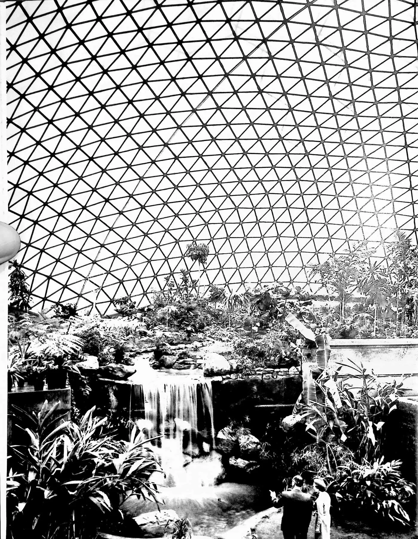
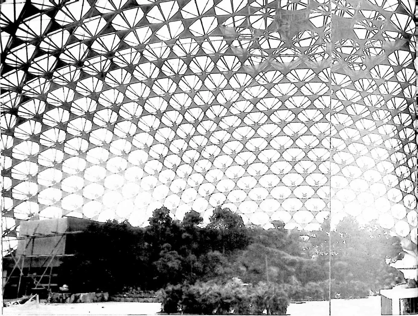
9 When I invented and developed my first clear-span, all-weather geodesic dome, the two largest domes in the world were both in Rome and were each 150 feet in diameter. They are St. Peter’s, built around a.d. 1500, and the Pantheon, built around a.d 1. Each weighs approximately thirty thousand tons. In contrast, my first 150-foot-diameter geodesic all-weather dome installed in Hawaii weighs only thirty tons—one-thousandth the weight of its masonry counterpart. An earthquake would tumble both the Roman 150-footers, but would leave the geodesic unharmed.
11 UNITED STATES PATENT OFFICE
12 Richard Buckminster Fuller, Forest Hills, N. Y.
13 INVENTIONS
14 130
15 BUILDING CONSTRUCTION
16 My invention relates to a framework for enclosing space.
17 SUMMARY
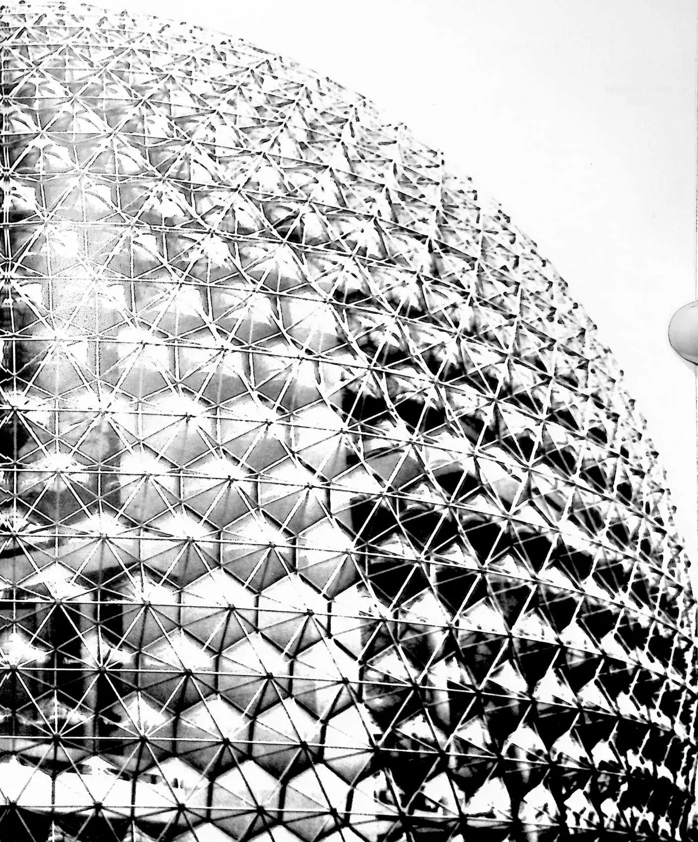
18 A good index to the performance of any building frame is the structural weight required to shelter a square foot of floor from the weather. In conventional wall and roof designs the figure is often 50 lbs. to the sq. ft. I have discovered how to do the job at around 0.78 lb. per sq. ft. by constructing a frame of generally spherical form in which the main structural elements are interconnected in a geodesic pattern of approximate great circle arcs intersecting to form a three-way grid, and covering or lining this frame with a skin of plastic material.
19 My ‘‘three-way grid’’ of structural members results in substantially uniform stressing of all members, and the framework itself acts almost as a membrane in absorbing and distributing loads. The resultant structure is a spidery framework of many light pieces, such as aluminum rods, tubes, sheets, or extruded sections, which so complement one another in the particular pattern of the finished assembly as to give an extremely favorable weight-strength ratio, and withstand high stresses. For example, the ‘‘8C270 Weatherbreak’’ constructed in accordance with my invention will support 7 lbs. with each ounce of structure and is able to withstand wind velocities up to 150 miles per hour. It is a dome 49 ft. in diameter, enclosing 20,815 cu. ft. of space, yet the frame is made of light short struts which pack into a bundle 2 ft. by 4 ft. by 5 ft., weighing only 1000 lbs. The plastic skin weighs 140 lbs., making the total weight of this ‘‘weatherbreak’’ a meref 1140 lbs.
20 Definition of terms
21 The basic and fundamental character of the inventive concept herein disclosed makes it desirable to define carefully certain terms some of which are used with special connotation, as follows:
22 Geodesic—Of or pertaining to great circles of a sphere, or of arcs of such circles; as a geodesic line, hence a line which is a great circle or arc thereof; and as a geodesic pattern, hence a pattern created by the intersections of great-circle lines or arcs, or their chords.
23 Spherical—Having the form of a sphere; includes bodies having the form of a portion of a sphere; also in-
24 FIGURE 3
26 FIGURE 4
28 eludes polygonal bodies whose sides are so numerous that they appear to be substantially spherical.
29 Icosahedron—A polyhedron of twenty faces.
30 Spherical icosahedron—An icosahedron ‘‘exploded’’ onto the surface of a sphere; bears the same relation to an icosahedron as a spherical triangle bears to a plane triangle; the sides of the faces of the spherical icosahedron are all geodesic lines.
31 Icosacap—Five spherical triangles of a spherical icosahedron, having a common vertex.
32 Grid—A pattern of intersecting members, lines or axes; usually intersecting great circles forming patterns made up of equilateral triangles, diamonds or hexagons.
33 Equilateral—Having all the sides approximately equal. The extent of variation in length of sides is determined trigonometrically or empirically by constructing three-way grids on the modularly-divided edges of the faces of a spherical icosahedron.
34 Modularly divided—Divided into modules, or units, of substantially equal length.
35 Framework—The frame of a structure for enclosing space; may be skeletal, as when made of interconnected struts; or continuous, as when made of interlocking or interconnected sheets or plates.
36 The meanings of these and other terms used in describing the invention will be more fully comprehended when considered with reference to the accompanying drawings and diagrams and the explanation thereof.
37 In its general arrangement, my building framework is one of generally spherical form in which the longitudinal centerlines of the main structural elements lie substantially in great circle planes whose intersections with a common sphere form grids comprising substantially equilateral spherical triangles. The visible pattern formed by the structural elements themselves does not necessarily show grids of equilateral triangles, for the visible grids may be equilateral triangles, equilateral diamonds or equilateral hexagons, the diamonds being made up of two equilateral triangles and the hexagons being made up of
38 six equilateral triangles. The individual triangles, diamonds, or hexagons as the case may be, may be made of straight or flat elements, in which circumstance they define flat or plane figures; or they may be made of arcuate or spherical form to define spherical figures. Either way, the complete structure will be spherical, or substantially so. And either way, the individual structural elements are so arranged as to be aligned with great circles of a common sphere.
39 In my preferred construction, the grids are formed on the faces of a spherical icosahedron. Each of the twenty equal spherical equilateral triangles which form the ‘‘faces’’ of this construction is modularly divided along its edges. Lines connecting these modularly divided edges in
40 A further general aspect of my preferred construction which may be noted here is that there is a ‘‘six-ness’’ throughout the pattern of structural elements on each face of the spherical icosahedron except that at each vertex, where five faces join at the center of an icosacap, there is a ‘‘five-ness.’’ In the case of a skeletal framework made up of struts in a pattern of equilateral triangles, this ‘‘six-ness’’ is manifested by the fact that there are six such triangles around every vertex except at the vertexes of the icosacaps where the ‘‘five-ness’’ is manifested by the fact that there are only five such triangles around those vertexes. Similarly, in the case of a continuous framework made up of diamond-shaped sheets, we find a ‘‘five-ness’’ only at the vertexes of the icosacaps where five
41 FIGURE 5
43 a three-way great circle grid provide the outline for the plan of construction. I have found that if the structural members be aligned with the lines of the grids, the resulting framework will be characterized by more uniform stressing of the individual members than is possible with any construction heretofore known. The structural members may be aligned with all lines of the three-way grid, or just with selected ones of those lines. If the members are arcuate, or spherical, they will coincide with the grid lines; if they are straight, or flat, they will be chords of the great circles which are the grid lines. sheets toe in to the one point. This aspect of five-ness and six-ness will be described more in detail further on, and need be mentioned only in general terms here so as to lay a foundation for the description of various specific frameworks built according to the invention.
44 DESCRIPTION
45 In the drawings:
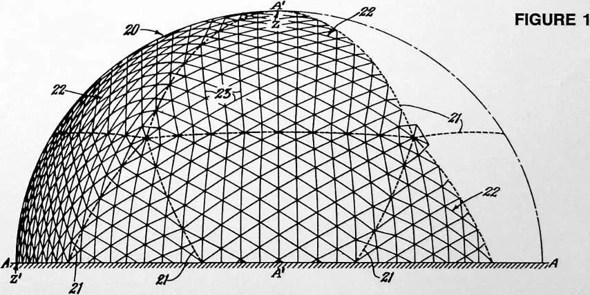
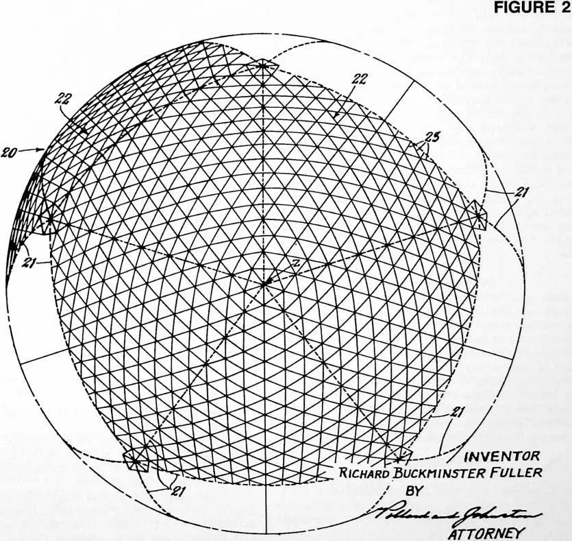
46 Fig. 1 is an elevational view of a building framework constructed in accordance with my invention and exemplifying a preferred form thereof; and Fig. 2 is a top
47 FIGURE 6

50 J
51 plan view of the same framework. These views are necessarily somewhat schematic because of the limitations imposed by the smallness of the scale to which they are drawn, making it impossible to show the detail of individual struts or of the fastenings which hold them together.
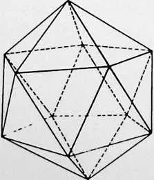
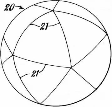
52 Fig. 3 is a diagrammatic perspective view of an icosahedron; and Fig. 4 a view of the same icosahedron after it has been ‘‘exploded’’ onto the surface of a sphere. These views are included to explain the structural basis of the main outlines of the framework of Figs. 1 and 2.
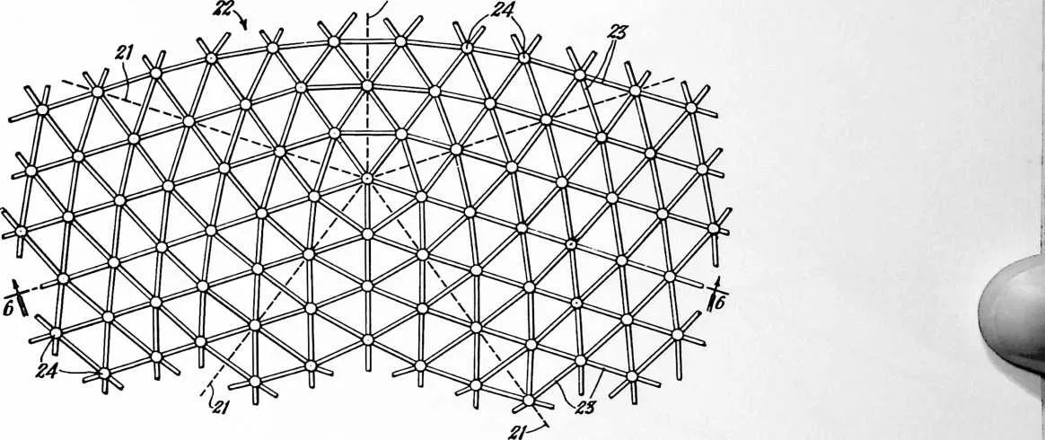
53 Fig. 5 is a detail plan view of a portion of the framework of Figs. 1 and 2, being that portion which immediately surrounds the top central vertex, i.e., the central part of the icosacap seen in Fig. 2.
54 Fig. 6 is a vertical section on the line 6--6 of Fig. 5.
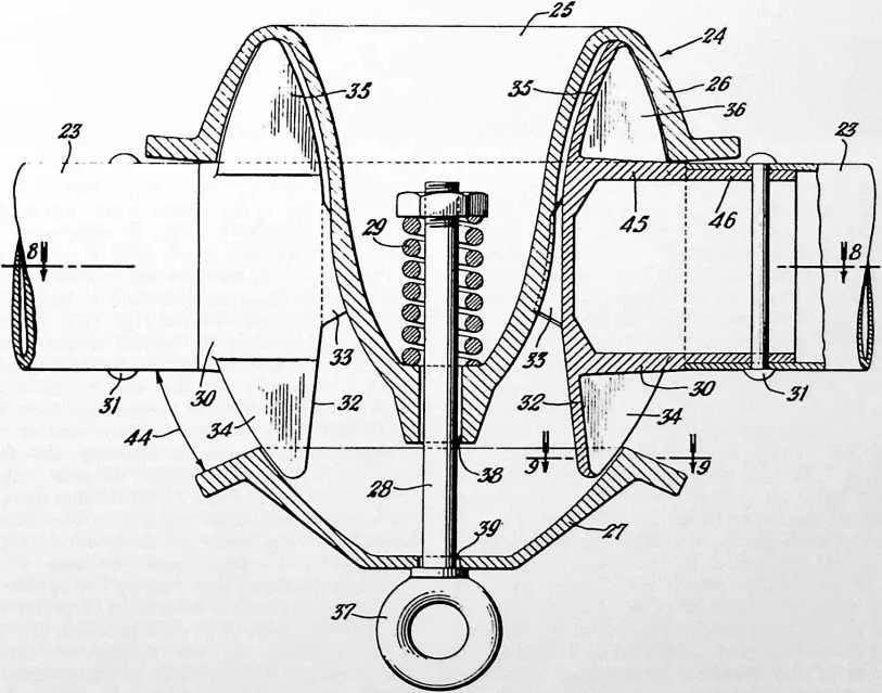
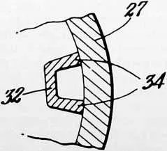
55 Figs. 7 and 8 are detail views of my preferred form of strut fastening. Fig. 7 is a central vertical cross-sectional view through the fastening with two struts fixed therein, one of these being shown in the central section and the other in elevation. Fig. 8 is a horizontal sectional view taken as indicated at 8--8 in Fig. 7, one of the struts being shown in elevation.
56 Fig. 9 is a detail sectional view taken on the line 9--9 of Fig. 7.
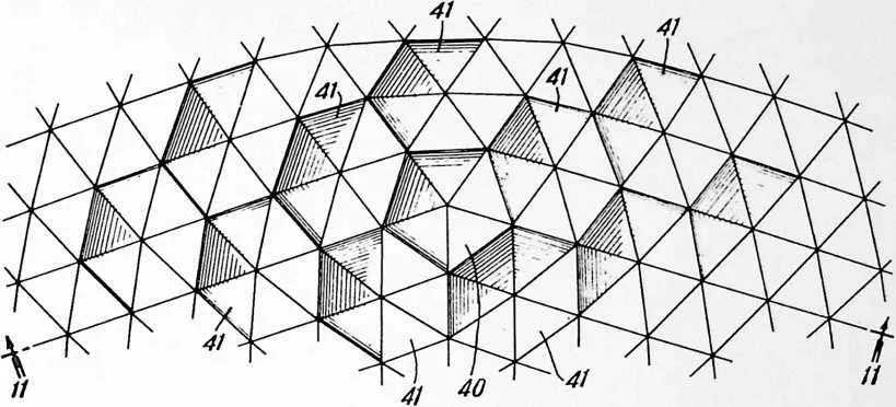
57 Fig. 10 is a diagrammatic plan view of a modified construction in which the vertexes of the pentagons and adjoining hexagons are offset inwardly to form an ‘‘involuted’’ truss-like structure. This view represents a portion of the framework similar to that shown in Fig. 5. However, instead of showing the framework itself, the planes of the equilateral triangles formed by the struts of the framework are shown as though they were triangular panels so as to permit shading of the view in such a way as to pictorialize the resulting ‘‘dimpled’’ surface.
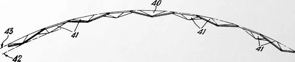
58 Fig. 11 is a diagrammatic cross-sectional view taken on the line 11--11 of Fig. 10.
59 Fig. 12 is a diagrammatic cross-sectional view similar to Fig. 11 showing a further modification in which the vertexes of the pentagons and adjoining hexagons are offset outwardly to form an ‘‘involuted’’ truss-like structure which is the inside-out of the structure of Fig. 11.
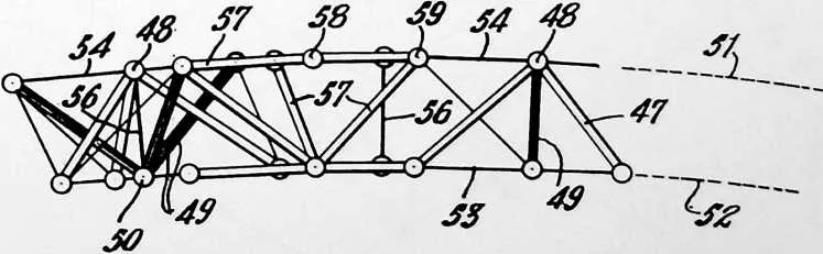
60 Fig. 13 is a fragmentary plan view of another embodiment of the invention, and Fig. 14 is a transverse sectional view of the same, taken as indicated at 14--14 in Fig. 13. Figs. 13a and 13b are detail perspective views of certain component parts of the truss illustrated in Figs. 13 and 14.
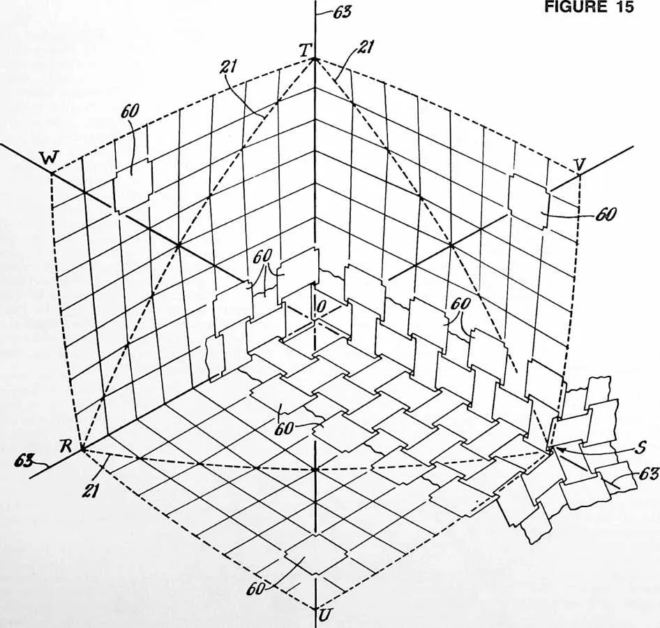
61 Fig. 15 is a diagrammatic plan view illustrating a portion of a framework in which the main structural elements consist of interconnected sheets.
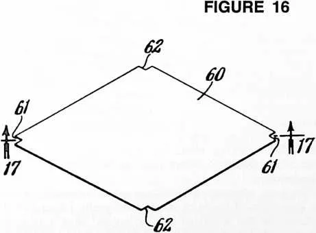
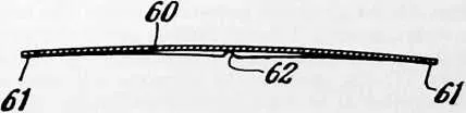
62 Fig. 16 is a detail plan view of one of the sheets used in the framework of Fig. 15, and Fig. 17 is a detail longitudinal sectional view of such a sheet taken as indicated at 17--17 in Fig. 16.
63 Fig. 18 is a further detail view of the Fig. 15 framework showing the manner in which four adjacent sheets are interconnected or interlocked.
64 The framework construction illustrated in Figs. 1 to 9 inclusive is representative of the best mode devised by me of carrying out my invention particularly as utilized in
65 FIGURE 7
68 structures up to approximately 50 feet in diameter. The struts which comprise the structural elements of this framework form a portion of a spherical icosahedron 20 whose modularly divided edges 21 are interconnected by three-way great circle grids 22. A spherical icosahedron has been defined above as an icosahedron ‘‘exploded’’ onto the surface of a sphere. This definition will be further explained by reference to Figs. 3 and 4, Fig. 3 being a diagrammatic perspective view of an icosahedron, and Fig. 4 a view of the same icosahedron exploded or projected onto the surface of a sphere. The icosahedron has twenty equal equilateral triangular ‘‘faces.’’ The spherical icosahedron has twenty equal equilateral spherical triangular ‘‘faces.’’ As used here, the term ‘‘face’’ refers to an imaginary spherical surface bounded by the sides or edges of one of the twenty spherical triangles.
69 The edges of each spherical triangle are modularly divided and are interconnected by the three-way great circle grids 22 previously mentioned. These grids are formed of a series of struts each of which constitutes one side of one of the substantially equilateral triangles defined by the lines of the grid. Each strut 23 is aligned with a great circle of the spherical icosahedron. Otherwise stated, the longitudinal centerline of each strut, or main structural element 23, lies substantially in a great circle plane. In the complete framework, the longitudinal centerlines of the main structural elements 23 lie substantially in great circle planes whose intersections with a common sphere form grids 22 comprising substantially equilateral triangles.
70 The number of modules into which each edge of the spherical icosahedron is divided is largely a matter of choice. In the framework of Figs. 1, 2, 5 and 6, the number is 16. Therefore we say the frequency is 16. But it might be 8 or 4 or some other number. Generally speaking, the larger the structure the greater will be the frequency selected in order to keep the sizes of individual struts within practicable limits for ease of manufacture, storage, packing, shipment, handling, and erection. I prefer to use light metal pieces for the struts, e.g., aluminum tubes as shown in Figs. 7 and 8. One metal alloy presently considered most suitable is the aluminum alloy known generally under the designation 61ST. A tubular strut size found satisfactory for structures 40 ft. in diameter is approximately 4 ft. long by 1%" outside diameter by 0.032" wall thickness. In general, I prefer to use struts which have a ratio of 24 units in length to 1 unit in transverse dimension, i.e., the ‘‘slenderness’’ ratio is 24 to 1. The frequency of the pattern as above defined can be selected with view to maintaining the optimum slenderness ratio for each size of framework.
71 The struts 23 may be interconnected by sliding joints
72 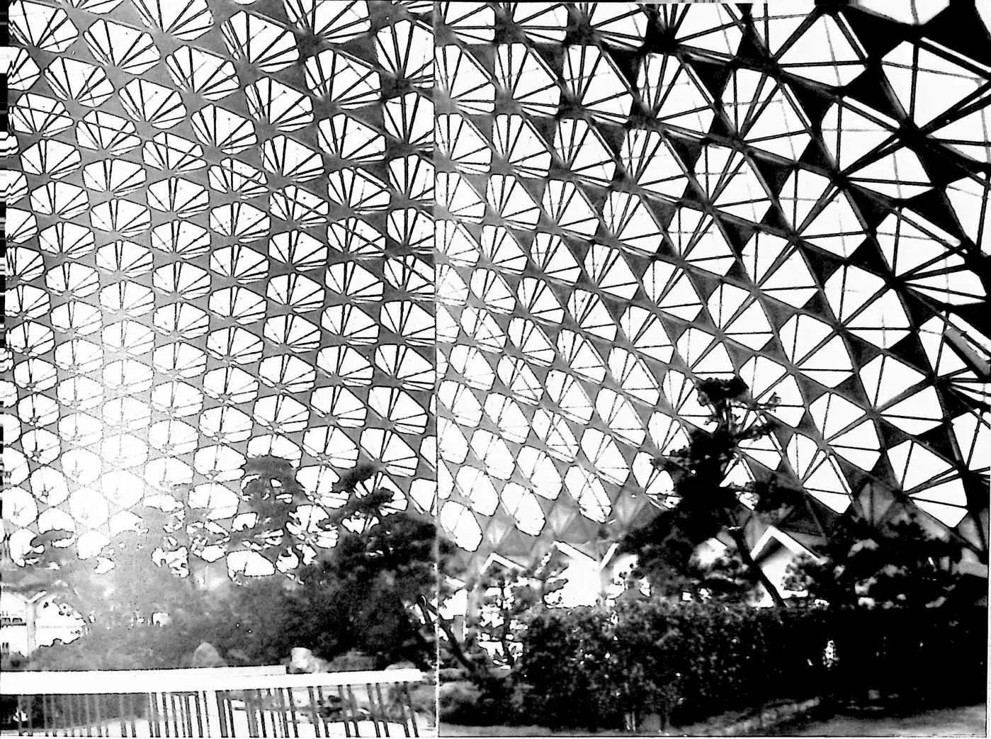 locked by gravity compression acting throughout the great-circle pattern of the framework
as a whole. In erecting the framework it is best to start by assembling the struts which are
to form the very top of the dome, i.e., at the center of the icosacap seen in Fig. 2.
This can be done on the ground. Working radially outward in all directions, the dome
will begin to take form and will gradually be lifted as the work proceeds until in the
end it rests with its lowermost struts against the ground or on a suitable foundation
prepared to receive it. It may be locked to the foundation by great circle bands or cables
preferably extending along the great circle lines which define the edges of the icosahedron.
If a poured concrete foundation is used, the lowermost struts and fastenings, or the
ends of such struts, may be embedded in the foundation, in which case the concrete,
or portions thereof, is poured after erection of the framework has been completed.
Alternatively, the lowermost struts and/or the fastenings may be anchored to individual
concrete foundation posts or to eye-bolts or other fastenings in such posts. In this
arrangement any suitable auxiliary fastenings may be used to lock the framework to the
foundation fastenings, such as bolts, cables, turnbuckle rods, etc., this being largely a
matter of choice depending upon the type of construction best suited for a particular
purpose.
locked by gravity compression acting throughout the great-circle pattern of the framework
as a whole. In erecting the framework it is best to start by assembling the struts which are
to form the very top of the dome, i.e., at the center of the icosacap seen in Fig. 2.
This can be done on the ground. Working radially outward in all directions, the dome
will begin to take form and will gradually be lifted as the work proceeds until in the
end it rests with its lowermost struts against the ground or on a suitable foundation
prepared to receive it. It may be locked to the foundation by great circle bands or cables
preferably extending along the great circle lines which define the edges of the icosahedron.
If a poured concrete foundation is used, the lowermost struts and fastenings, or the
ends of such struts, may be embedded in the foundation, in which case the concrete,
or portions thereof, is poured after erection of the framework has been completed.
Alternatively, the lowermost struts and/or the fastenings may be anchored to individual
concrete foundation posts or to eye-bolts or other fastenings in such posts. In this
arrangement any suitable auxiliary fastenings may be used to lock the framework to the
foundation fastenings, such as bolts, cables, turnbuckle rods, etc., this being largely a
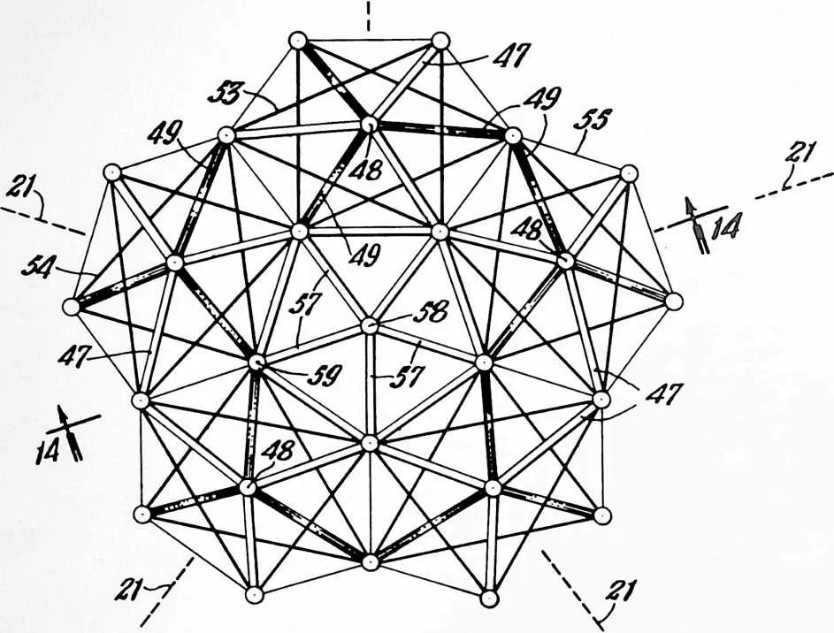
matter of choice depending upon the type of construction best suited for a particular
purpose.
73 Referring again particularly to Figs. 1 and 2, the ground line or foundation line is indicated at A—A in Fig. 1, and the components of the framework are so oriented that the midpoint of the pentagon at the center of an icosacap coincides with the zenith Z of the framework. In some cases, however, it may be preferred to shift the orientation of the framework, as for example to an orientation which would result from using the line A'—A' as the ground or foundation line, in which case the zenith Z' would no longer coincide with the midpoint of an icosacap but instead would coincide with a point within one of the spherical triangles which form the faces of the icosahedron. If the sheet of the drawing on which Fig. 1 appears to be turned so that its right-hand longer edge becomes the bottom of the sheet, that part of Fig. 1 which is bounded by Z'A'A', becomes the right-hand portion of the reoriented framework. Note that with this particular orientation, the base line A'A' is a geodesic line completely defined by struts of the framework. This provides a convenient foundation line and one which lends itself well to anchoring of the framework to its foundation. In Figs. 1 and 2, however, I have chosen the zenith Z orientation in order to provide a clear illustration in Fig. 2 of a complete icosacap as defined hereinabove.
74 One of the characteristics of the completed framework is that it is virtually self-locking. Once properly as-
75 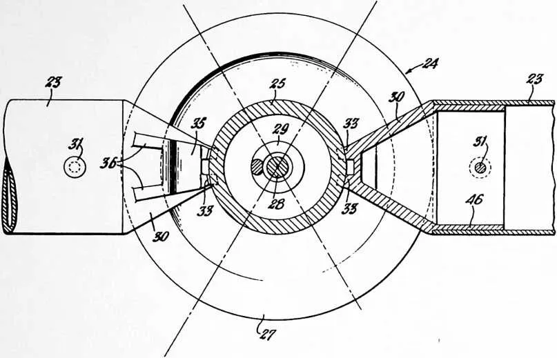 sembled in the manner described, it will not come apart except by more or less uniform
expansion of all its parts. However, because the framework is somewhat resilient, localized forces
acting outwardly against the inside of the structure may under certain conditions tend to expand
one portion of the framework and produce what might be described as something akin to a
blowout in a pneumatictire. To resist such forces, and to assist in holding the struts together
during erection, it is best that the means for fastening the ends of the struts be such as to lock
them positively in place, in this respect supplementing the self-locking action described above,
and giving added strength to the framework by reason of the fixed-end construction thus
provided.
sembled in the manner described, it will not come apart except by more or less uniform
expansion of all its parts. However, because the framework is somewhat resilient, localized forces
acting outwardly against the inside of the structure may under certain conditions tend to expand
one portion of the framework and produce what might be described as something akin to a
blowout in a pneumatictire. To resist such forces, and to assist in holding the struts together
during erection, it is best that the means for fastening the ends of the struts be such as to lock
them positively in place, in this respect supplementing the self-locking action described above,
and giving added strength to the framework by reason of the fixed-end construction thus
provided.
76 136
77 My preferred form of fastening is shown in Figs. 7--9. It is a ball-like ‘‘fist’’ configuration designated generally at 24, comprising complementary parts 25 and 27. In the specific construction illustrated, 25 is the outer part and 27 the inner part. These parts are clamped together by means of a bolt 28, a coil spring 29 being provided to afford a certain amount of resiliency in the fastening, which is particularly useful during erection of the structure. As seen in Fig. 7, outer part 25 is in the general form of an inverted bell, the edge of which is turned back on itself to provide a curved flange 26 complementary to the curved flange of inner part 27. Affixed to each end of each strut 23 is an attaching member 30 having a tubular body portion 45, the shouldered end 46 of which fits within the end of the strut. Attaching member 30 may be secured to the strut 23 by means of a rivet, pin, or bolt 31. Each fastening member has an inwardly extending lug 32 and an outwardly extending lug 35. Lug 32 has a pair of flanges 34 with arcuate edges conforming to the arc of the inner surface of inner part 27 of the fastener. Similarly lug 35 has a pair of flanges 36 whose arcuate edges conform to the inner surface of flange 26 of outer part 25. A pair of flanges 33 at the end of fastening 30 have arcuate edges conforming to the outer surface of the bell-like portion of outer fastening 25. The arrangement is such that the longitudinal centerline of struts meeting at any particular fastening 24, 27 can be adjusted to different angles so that the struts will form chords of great circles of the framework as a whole. As the framework is erected, it will tend to assume the general spherical form of the dome for which parts have been designed. Once it has assumed such form, the individual fastenings are tightened, compressing the coil springs 29 to the desired extent. If the fastenings are tightened to the extent which
79 FIGURE 9
81 FIGURE 11
83 FIGURE 12

87 ENTIONS
88 140
89 i

91 compresses springs 29 until they are driven solid, maximum rigidity is obtained. However, if greater flexibility is desired in the completed structure, bolts 28 will be tightened to a lesser extent, in which case the springs 28 will not be driven solid. Suitable lock nuts or lock washers may be used to hold the parts in the desired final adjustment.
92 In Fig. 7, bolt 28 is provided with an eye 37 at its inner end which is useful in attaching the plastic skin inside of the framework. Bolt 28 passes through openings 38, 39 in the outer and inner parts 25, 27 respectively of fastening 24.
93 Reference is now made to the modified construction illustrated in Figs. 10 and 11. Fig. 10 represents a portion of the framework similar to that shown in Fig. 5. However, instead of showing the framework itself, the planes of the equilateral triangles formed by the struts of the framework are shown as though they were triangular panels (instead of spaces outlined by the struts). This has been done to permit use of shading in such a way as to pictorialize the ‘‘dimpled’’ surfaces of this particular framework. The ‘‘dimples’’ are formed by inwardly offsetting the vertexes of the pentagons 40 and adjoining hexagons 41 to form what I term an ‘‘involuted’’ trusslike structure. This places all the inwardly offset vertexes substantially in a spherical surface 42 concentric with the main spherical surface 43. The main spherical surface is defined by the ends of the struts of the bases of the pentagons 40 and hexagons 41. The resulting structure is like a spherical truss defining inner and outer substantially spherical surfaces of concentric spheres. This framework based on two spheres is somewhat stiffer and less resilient than the framework of Figs. 1 and 2 based on a single sphere, and I consider the former best suited for the construction of domes in sizes ranging between approximately 50 and 140 feet in diameter. The struts which extend inwardly to the vertexes or points of the dimples are made somewhat longer than they would be in the single sphere construction so that, upon assembly, formation of the dimples is an inherent function of the lengths of the respective struts.
94 In the further modification illustrated by Fig. 12, the dimples are inverted. This framework, and the framework of Figs. 10 and 11, can be made of the same kind of struts described with reference to Figs. 5 and 6, and can be put together with the same type of fastening described
95 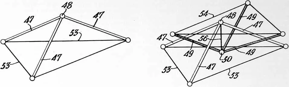 with reference to Figs. 7 and 8, although if desired other forms of struts and
fastenings can be used within the limits of the appended claims. It will be observed that
the fastenings of Figs. 7 and 8 allow for offsetting of the selected vertexes. (Note the
clearance at 44.) Note also that in these modified constructions the struts which extend to
the offset vertexes, while no longer lying substantially in a spherical surface, still are
aligned with great circles of a common sphere; and such struts still lie substantially in
great circle planes whose intersections with a common sphere form grids comprising
equilateral triangles. These inwardly extending struts also are chords of great circles of the
framework.
with reference to Figs. 7 and 8, although if desired other forms of struts and
fastenings can be used within the limits of the appended claims. It will be observed that
the fastenings of Figs. 7 and 8 allow for offsetting of the selected vertexes. (Note the
clearance at 44.) Note also that in these modified constructions the struts which extend to
the offset vertexes, while no longer lying substantially in a spherical surface, still are
aligned with great circles of a common sphere; and such struts still lie substantially in
great circle planes whose intersections with a common sphere form grids comprising
equilateral triangles. These inwardly extending struts also are chords of great circles of the
framework.
96 Reference is now made to another embodiment of the invention as illustrated in Figs. 13 and 14. This is a variant of the frameworks of Figs. 10--12; like them, it is based on two spheres. However, the framework of Figs. 13 and 14 is more complex, and comprises a truss formed of compression and tension members. I consider this type of framework best suited for the construction of domes in sizes from approximately 140 feet in diameter and upward. Fig. 13 covers a small area of the framework centering about the pentagon at the midpoint of an icosacap, i.e., an area corresponding to the central portion of Fig.
97  5 (except of course, that this is a different type of framework than that shown in Fig. 5).
The framework is made up of struts similar to the struts 23 described with reference to the
framework of Figs. 1, 2, 5, and 6, these struts being connected together by fastenings which may
be similar to those described with reference to Figs. 7--9. The framework may be considered as
made up of a series of tripods, one of which is shown in Fig. 13a, consisting of three
struts 47 joined at the center of the tripod by fastening 48. This particular tripod
may be described as an outwardly pointing tripod. Its central vertex as represented
by fastening 48 lies in the main, or outer, spherical surface 51 and its base lies in
spherical surface 52 concentric with surface 51. Arranged in complementary fashion to the
outwardly pointing tripods are inwardly pointing tripods made up of three struts 49 joined
together by fastening 50. Its central vertex as represented by fastening 50 lies in the
inner spherical surface 52 and its base lies in the outer spherical surface 51. Two such
complementary tripods are shown in Fig. 13b. The feet of the outwardly pointing tripods
are joined together by tension members 53 which may be made of wires or cables.
The feet of the inwardly pointing tripods are connected by similar tension members
54.
5 (except of course, that this is a different type of framework than that shown in Fig. 5).
The framework is made up of struts similar to the struts 23 described with reference to the
framework of Figs. 1, 2, 5, and 6, these struts being connected together by fastenings which may
be similar to those described with reference to Figs. 7--9. The framework may be considered as
made up of a series of tripods, one of which is shown in Fig. 13a, consisting of three
struts 47 joined at the center of the tripod by fastening 48. This particular tripod
may be described as an outwardly pointing tripod. Its central vertex as represented
by fastening 48 lies in the main, or outer, spherical surface 51 and its base lies in
spherical surface 52 concentric with surface 51. Arranged in complementary fashion to the
outwardly pointing tripods are inwardly pointing tripods made up of three struts 49 joined
together by fastening 50. Its central vertex as represented by fastening 50 lies in the
inner spherical surface 52 and its base lies in the outer spherical surface 51. Two such
complementary tripods are shown in Fig. 13b. The feet of the outwardly pointing tripods
are joined together by tension members 53 which may be made of wires or cables.
The feet of the inwardly pointing tripods are connected by similar tension members
54.
98 FIGURE 14
100 142
101 In Figs. 13 and 14, the struts 47 of all of the outwardly pointing tripods have been shown without any surface shading so that they appear light in the drawing, whereas the struts 49 of all the inwardly pointing tripods have been shown with surface shading so that they appear dark in the drawing. Thus, the ‘‘light’’ tripods are disposed with their vertexes in spherical surface 51 and the ‘‘dark’’ are disposed with their vertexes in spherical surface 52. Tension members 55 extend diagonally between the respective feet of the light and dark tripods. These tension members, as viewed in plan in Fig. 13, present a hexagonal outline, alternate comers of which are connected by the aforesaid tension members 53 and 54, tension members 53 forming a triangle made up of chords of spherical surface 52 and tension members 54 forming a triangle made up of chords of spherical surface 51. The resultant basic pattern of the outer spherical icosahedron in surface 51 is the same as that illustrated in Fig. 5. The same is true with respect to the resultant basic pattern of the inner spherical icosahedron in surface 52. In effect, therefore, we have here two concentric spherical icosahedrons joined by diagonal struts and tension members. The framework is tightened into a final rigid structure by means of tension members 56 extending radially with respect to spherical surfaces 51 and 52 between the fastenings 48 and 50 at the apexes of the light and dark tripods respectively. If desired, turnbuckles may be used in these tension members to secure the desired final tension to hold the structure with the proper degree of rigidity.
102 At the vertexes of the icosacap, the framework assumes a pentagonal form as clearly shown at the center of Fig. 13. At such points in the structure we have an inwardly (or outwardly) pointing pentagonal strut arrangement in place of the two complementary tripods which characterize the rest of the framework where the pattern is hexagonal. I prefer to bridge over the outer side, or
104 143
105 base, of the pentagonal strut arrangement at each vertex. In the specific framework shown, this bridging consists of five struts 57 joined together by fastenings 58 at the vertexes of the spherical icosahedron, and joined by fastenings 59 to the feet of the light and dark tripods immediately adjoining the respective pentagons.
106 In all of the forms of framework I have described, the lengths of the individual struts, are substantially equal, but not precisely so. The slight differences in the lengths of different struts in a given framework determine the radius of the dome and whether it is based on one or two spheres. The number of different lengths of strut in any given framework based on a spherical icosahedron varies in accordance with the number of units, or modules, into which the edges of the spherical icosahedron are divided, i.e., in accordance with what I have previously termed the ‘‘frequency’’ of the three-way great circle grids. I have found that with a frequency of 16, as described in connection with the dome illustrated in Figs. 1, 2, 5 and 6, all conditions of the framework design are satisfied with 56 different lengths of strut. The same framework when built of grids having a frequency of 8 can be constructed from struts in 16 different lengths. With a frequency of 4, only 5 different lengths would be used. I have found, further, that there need never be any greater
108 complication as to number of lengths of struts than that represented by a frequency of 16.
109 The slight differences between the lengths of the individual struts in tum create slight differences between the angles of the substantially equilateral triangles and this has the result of forming a spherical grid structure in which all the main structural members are in geodesic alignment or are chords of great circles of a common sphere. One way of determining the strut lengths is to construct a paperboard hemisphere to a scale of, say, 1 inch to 1 foot, and lay out the vertexes of one of the faces of a spherical icosahedron on its surface. These vertexes are next connected by drawing great circle lines (spherical straight lines) therebetween. The edges of the triangle defined by these lines are next divided equally into the number of units represented by the selected grid frequency. The division points are then connected by drawing great circle lines in the manner clearly shown in Figs. 1 and 2. (Note that the points along one edge are connected to every second point on another edge.) We now have a completed three-way grid pattern. Finally the length of the chordal struts is measured directly with the use of ordinary draftsman’s dividers, allowance being made for the strut fastenings.
110 Figs. 15 to 18 inclusive illustrate another embodiment of my invention in which the main structural elements of the framework consist of interconnected sheets 60 of metal, plastic or other suitable material. The longitudinal centerlines (17—17, Fig. 16) of these sheets lie substantially in great-circle planes whose intersections with a common sphere form grids comprising substantially equilateral triangles. As shown the sheets are substantially in
111 FIGURE 17
129 62
130 the form of equilateral diamonds whose minor axes are approximately equal in length to the sides. The corners of the sheets 60 are notched for interlocking engagement with the notches of adjacent sheets. The corners of the notches 61 and 62 lie substantially in great circle planes whose intersections with a common sphere form grids of substantially equilateral spherical triangles. Thus the sheets 60, like the struts 23 of the framework illustrated in Figs. 1 and 2, are in geodesic alignment. The alignment is such that the longitudinal centerlines of the sheets (and also their edges) are arranged in geodesic lines. Thus these sheets create the same sort of three-way grid pattern as I have described with reference to the several forms of framework in which struts are employed.
131 Here again, all the main structural elements are of almost the same size, the variation being determinable mathematically or by graphic solution as before. The frequency of the grids is a matter for selection in accordance with the special requirements of particular structures. As with the struts, the frequency will determine the number of different diamond sizes to be used in a given framework design. With a frequency of 16, for example, there will be 20 sizes or types of diamond per sphere. With hexagonal sheets on the same three-way grids, and with a frequency of 16, there will be 10 types per sphere, consisting of 9 types of approximately hexagonal sheets and 1 pentagonal sheet. Other forms and arrangements are possible.
132 Particular attention is directed to the manner in which the three-way grid pattern is built up in this form of my framework. Fig. 15 shows one complete face, or spherical triangle RST, of the spherical icosahedron, plus one-third of each adjoining face of the same, namely the additional areas RUS, SVT and TWR, or the total area RUSVTW. Geodesic lines 63, 63, 63 extend from each vertex of RST through the mid-point of the opposite side. SV, VT, TW, etc., are corresponding geodesic lines of the adjoining faces of the spherical icosahedron. Within area RUSO all of the sheets 60 are arranged with their longitudinal centerlines extending in one general direction. The same is true within areas SVTO and TWRO, except that in each case the general direction is different. Along lines RO, SO and TO, the sheets of the respective adjoining areas come together at an angle approximately equal to one of the spherical angles of spherical triangle RST. This can best be understood by noting the diamond patterns of the construction lines where they extend beyond the area covered by the sheets 60. Note that at the vertexes of the icosacaps (as at S for example), five sheets 61 toe in to a common point. Elsewhere throughout the framework as shown in Fig. 18 four sheets toe in to a common point, except at the center O of the triangle RST where only three sheets toe in at a common point. Thus there are five sheets around each of the vertexes R, S and T, three sheets around centers O, U, V and W and four sheets around all intermediate points.
133 With this general type of construction, I have discovered the possibility of making all the sheets exactly identical in overall size, the variation in type being secured by varying the sizes or depths of the notches 61 and 62. If the overlapping edges of adjacent sheets are riveted together, the holes for the rivets will be drilled on slightly different patterns to suit the different types and keep the fastenings in geodesic alignment. Thus all the sheets are sheared out to one size, and the manufacture of the different types for a particular sphere is completed by using adjustable jigs (or a series of different jigs) for the notching and/or drilling or punching tools. This greatly simplifies manufacture.
134 I prefer to form or press the sheets to a compound curvature conforming to the surface of the spherical icosahedron on which they are based.
135 Domes constructed in accordance with Figs'. 15--18 may be erected by first assembling on the ground those sheets which are at the vertex of an icosacap, namely at that vertex which will be uppermost in the completed framework. Then, working around peripherally, additional sheets are interlocked and/or riveted together, raising the partially completed dome as the work progreses.
136 It is possible to begin interlocking the sheets in either a clockwise overlapping relationship, or in a counterclockwise overlapping relationship. By a clockwise overlapping relationship, I mean that at any given point where a group of sheets toe in to a common vertex, the edge of each successive sheet of the group is on top of the preceding sheet as we move around the vertex in a clockwise direction. By a counterclockwise overlapping relationship, I mean that at any given point where a group of sheets toe in to a common vertex, the edge of each successive sheet of the group is on top of the preceding sheet as we move around in a counterclockwise direction. This imposes what I term a ‘‘turbining’’ action in the framework, and the turbining action will be either clockwise or counterclockwise according as the overlapping relationship is either clockwise or counterclockwise. These turbining actions produce a highly effective locking action in the framework as a whole.
137 Geodesic locking bands or cables may be tensioned over the completed dome and anchored to a suitable foundation.
138 Geodesic frameworks constructed in accordance with my invention, if made of struts universally jointed at the vertexes of the triangles can be folded into a compact bundle without taking apart any but the final locking elements. This form of my invention is ideally suited for use as temporary shelters which are to be moved from place to place, such as huts, hangars, mess-halls, and headquarters units for army encampments.
139 The frameworks may be covered with plastic skins, inside or outside or both, or with other materials. Openings for access, light, sun and air are provided as desired.
140 The terms and expressions which I have employed are used in a descriptive and not a limiting sense, and I have no intention of excluding such equivalents of the invention described, or of portions thereof, as fall within the purview of the claims.