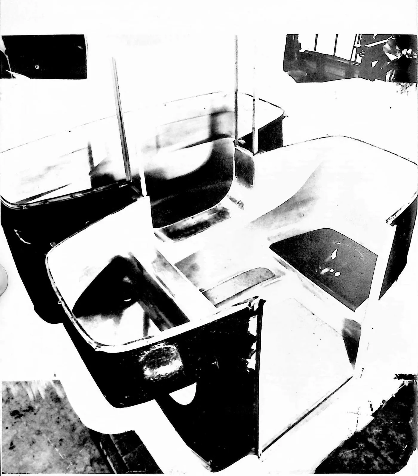
4 DYMAXION CAR (1937)
2U.S. PATENT—2,101,057
APPLICATION—OCTOBER 18, 1933
SERIAL NO.—694,068
3 IN GREAT BRITAIN—SEPTEMBER 8, 1933
PATENTED—DECEMBER 7, 1937
4 FIGURE 1
7 SINCE I WAS INTENT ON DEVELOPING a high-technology dwelling machine that could be air delivered to any remote, beautiful country site where there might be no roadways or landing fields for airplanes, I decided to try to develop an omni-medium transport vehicle to function in the sky, on negotiable terrain, or on water—to be securely landable anywhere, like an eagle.
8 There are two kinds of birds—soaring birds like gulls and nonsoaring birds like ducks, whose wings are too small to soar. Birds with wings too small to soar can flap their small wings very powerfully against their body, producing air jets, and can do so in such a manner as to make the jets orientable forwardly, backwardly, inwardly, and outwardly. All our heavier-than-air aeronautical development has been of the soaring-wing type. The structural weights of the ‘‘main spars’’ and of the wing-routes, etc., are great. I saw that with the duck-type nonsoaring jet flying device, much weight could be saved.
9 The first full-scale experimental building of what I called the 4D (four-dimensional) transport was undertaken to discover the ground-taxiing controlling requirements of an omni-streamlined vehicle that would ultimately be developed into a twin orientable jet-stilts, flyable vehicle. Such a vehicle had to be superbly faired, i.e., streamlined.
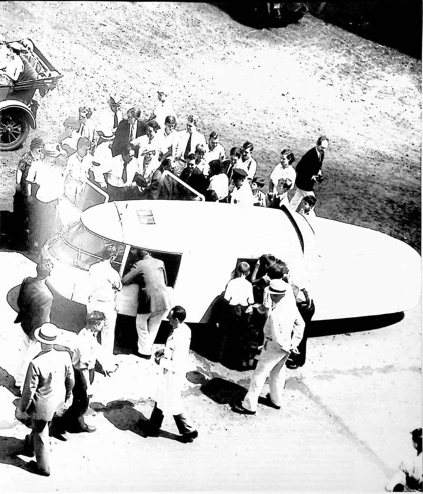
10 Everything in Universe is in constant motion. Everything in Universe is always moving in the direction of least resistance. When what we call a light plane, one flown by an individual, lands crosswind, its fairing or streamlining makes it want to turn violently in the direction of the wind—the direction of least resistance. This is called ground looping. I realized that the most difficult conditions for my omni-medium jet-stilt superbly faired flying device would be when it was on the ground. What is popularly called the Dymaxion Car were the first three vehicles designed to test ground taxiing under transverse wind conditions.
11 I produced only these three prototypes, the first with financial help from a friend, the other two with all of the money I inherited from my mother.
13 32
14 UNITED STATES PATENT OFFICE
15 Buckminster Fuller, Bridgeport, Conn., assignor to the Dymaxion Corporation, Bridgeport, Conn., a corporation of Connecticut
16 MOTOR VEHICLE
17 The invention relates to the construction of motor road vehicles whereby they are adapted to the economical operation resulting from full streamline formation and whereby other and independent advantages are obtained as will be apparent to those skilled in this art from this disclosure. The principles of the invention are exemplified by the vehicle illustrated in the accompanying drawings, but without limitation to such particular form.
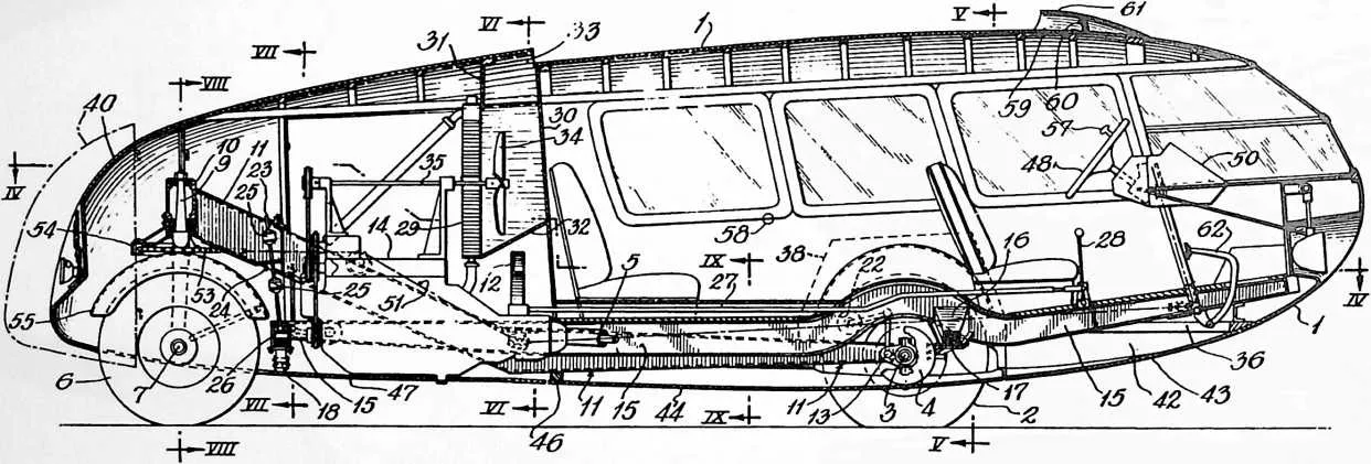
18 Fig. 1 is a side view of the vehicle.
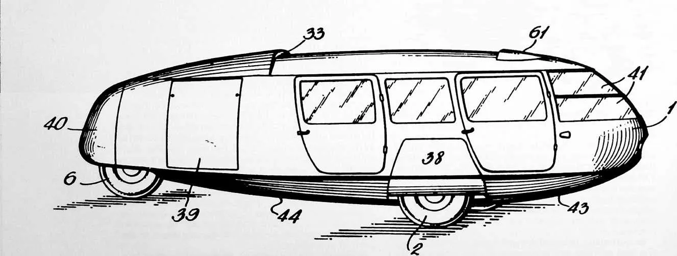
19 Fig. 2, a top plan.
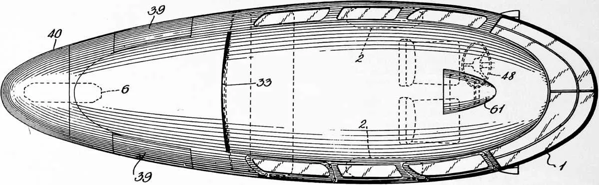
20 Fig. 3, a longitudinal vertical section.
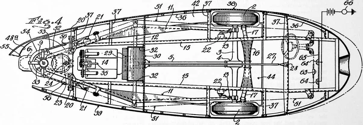
21 Fig. 4, a horizontal section on line IV—IV.
22 Fig. 5, a cross section on line V—V.
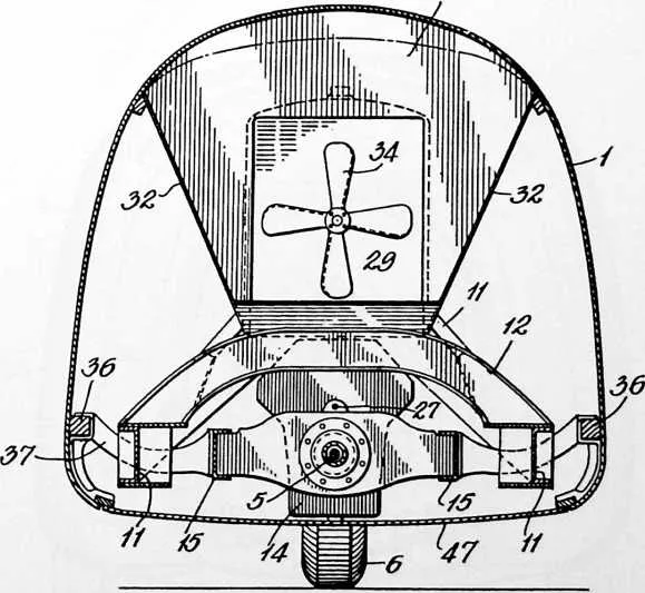
23 Fig. 6, a cross section on line VI—VI.
24 Fig. 7, a cross section on line VII—VII.
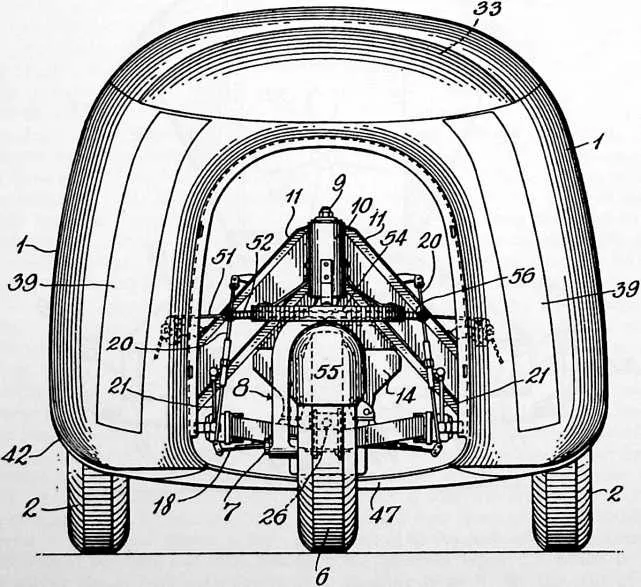
25 Fig. 8, an end view at line VIII—VIII with bussle removed.
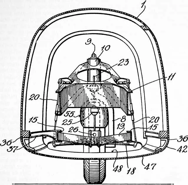
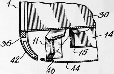
26 Fig. 9, a detail section on line IX—IX.
27 The streamline body covers or encloses all of the chassis including all the wheels. For best economy it should be so designed that every axial section has a full streamline contour, which is to say that the body should be continuously curved from a round or blunt front to a tapered tail and that all its transverse maximum diameters should occur at a point about one-third of the length from the front end with no substantial interruption to the curvature and with no more excrescencies exposed to the relative wind than necessary for operation. The front wheels 2 are the driven or traction wheels and are located at the widest part of the streamline body, that is, at a point about one-third of its length from the front end. They are journalled at the ends of an axle structure or housing 3 and driven through differential gearing indicated at 4 by a propeller shaft 5 or in any equivalent differential manner. The axle structure may be the same as the rear axle structure of standard automobiles.
28 The forward wheels can be organized as the steering wheels within the broader aspect of this invention, but it is preferred that the steering is done by a rear wheel or wheels such as indicated at 6 which is central of the two forward wheels, being journalled on a stub shaft 7 rigidly fixed in the end of a single-tined steering fork 8, the head 9 of which is swiveled to turn on an upright axis. This wheel is preferably of the same size as the forward wheels and interchangeable therewith as in standard automobiles, being readily removed from its stub shaft on the single-tined fork. It may however be dual-tired if desired, or may consist of twin wheels turning together as a unit or like a single wheel and such variants are to be understood as included within the term single steering wheel as used herein.
29 The steering head 9 is journalled on vertically spaced bearings in a deep barrel socket 10 formed in the rear apical end of a generally triangular or A-shaped frame 11 herein termed the sub-frame, and is slightly castored therein as shown in Fig. 3, to facilitate steering. The forwardly extending legs of this frame 11 are supported on the forward axle housing 3 close to the front wheels 2, thus to provide a wide bearing for the sub-frame on the
31 forward wheels and it has deep web sections with liberal flanging and gusseting and is reinforced by an arched cross-brace 12, all for the purpose of producing a maximum degree of rigidity in the torsional sense between the steering head and axle housing. Such rigidity is important in three-wheeled vehicles intended for passenger car speeds because, if the steering axis is not kept to a plane parallel with the planes of the front wheels (or if these are canted, then to an intermediate plane bisecting the angle between them) the steering becomes unsteady and dangerous. On this account the sub-frame 11 is specially stiffened as stated and no spring intervenes between it and the wheels such as might permit the steering axis to change its lateral position in relation to the forward wheels. In this sense the sub-frame is an unsprung frame. It may however be connected to the axle by a This frame extends from a rear point just forward of the rear wheel to a forward point well beyond the forward wheels and has a kickup over the forward axle. Its rear part lies in substantially the same level as the legs of the sub-frame and between them and about one-third of its length overhangs the forward axle. Cross bracing, not shown, may be provided to give it requisite stiffness. Its forward point of support is by a cross bolster 16 and a transverse spring 17 which is shackled at its ends to appropriate brackets on the axle structure; see Fig. 5. At its rear end it is flexibly connected to the sub-frame in such manner as to accommodate the action of the forward spring and preferably the connection includes a spring such as cross-spring 18 which is centrally fastened to the cross-bolster 19 of the main frame and suspended at its ends by a pair of hanger-links 20 depending from the high
32 FIGURE 3
34 joint, if the joint axis is horizontal and such joint is preferably used and appears at 13, where the ends of the frame legs are attached to the axle housing. It does not impair the rigidity of the frame against torsion. Preferably also the sub-frame is dropped or formed with an angle at or near the cross brace so that its forwardly extending leg members are substantially horizontal and at about the level of the wheel hubs and only the pointed rear part rises above the hub level.
35 The propelling engine 14 occupies the space within and below the narrow part of the sub-frame and under the arched cross-brace 12. It may be mounted on that frame with appropriate cushionings, if desired, but is preferably mounted on a second frame 15, herein called the main frame, which carries the body 1 and is spring-supported. part of the sub-frame. These links include turn-buckles, as indicated, which can be adjusted to raise or lower the main frame. By reason of their substantial parallelism they permit a certain amount of sidesway to the main frame relatively to the sub-frame but tending at the same time to restrain careening of the body.
36 The chassis of the illustrated vehicle thus includes the sub-frame which as stated is unsprung, and the main frame which is sprung both front and rear. It is desirable that the normal amplitude of the rear spring action be relatively less than that of the front spring. This can be done by loading it with a resistance of some sort, such as provided by connecting ordinary hydraulic shock absorbers 21 between the two frames at this point. If absorbers are also associated with the front spring, as indicated at
37 22, the resistance of the rear absorbers is made to exceed materially that of the front absorbers, so that the action of the rear spring is relatively stiff or sluggish. The throw of the rear spring is limited by a check rod 23 which is connected at its foot with the end of the main frame or with the cross bolster 19 thereof or otherwise and plays in a hole in a cross flange 24 (Fig. 3) of the sub-frame 11 with rubber-backed collars 25 fixed on the rod above and below such flange. These collars coact with the flange as spring-bumpers, in both directions, and in addition the upper collar serves also as a safety support to hold the main frame in the event of failure of its rear spring or support. The engine is mounted with the end of its crankshaft accessible to the rear through a hole marked 26 and the check rod is attached to the frame by a connection above this hole, as indicated in Figs. 3 and 7 so that by the cabin compartment, and suitable partitions 31 and 32 (Fig. 6) are provided to form an air channel for conducting air to it from an air scoop slot 33 which extends across the roof part of the body. A fan 34 is located in the air channel, being driven by the engine in any suitable manner, as for example, by the belt-driven shaft 35, which is journalled on the engine and extends through the radiator. The cooling air passing the radiator flows over the engine and out around the rear wheel.
38 While the body 1 can be variously constructed and wholly of metal, if desired, it is shown as built of wood framing with a light metal covering. Its main sills 36 are carried on brackets 37 which project laterally from the main frame, some of them extending over and some under the legs of the sub-frame and all shaped or located to afford the necessary clearance for the relative movement
39 FIGURE 4
41 turning the steering wheel to a transverse position room is available to introduce a hand crank in the hole when the engine requires to be hand cranked.
42 The transmission case is on the forward end of the engine and connected to drive the forwardly extending propeller shaft 5 through an appropriate universal joint or joints and with or without a torque tube as preferred. The transmission mechanism is controlled by a selector rod 27 extending forwardly to the gear shift lever 28 at the operator’s station. The usual engine controls, though not shown in the drawings, will be understood to be arranged in any suitable way.
43 In the case of a watercooled engine, the radiator 29 is preferably located directly over the transmission or flywheel case and just abaft the after bulkhead wall 30 of of the unsprung sub-frame and the sprung main frame. These sills extend aft of the main frame as cantilevers to support the tail part of the body. Doors and windows are provided and also a number of removable panels, those marked 38 being for providing access to the forward wheels and those marked 39 to afford access to the engine while the rear end or bussle 40 is removable to afford access not only to the rear wheel but also to the crankshaft of the engine for hand-cranking it. The forward windows 41 are either curved to the streamline contour or composed of smaller flat sections collectively approximating such contour.
44 The bottom of the body is preferably closed by a belly wall in one or more sections which are longitudinally and transversely curved to conform to the streamline contour.
45 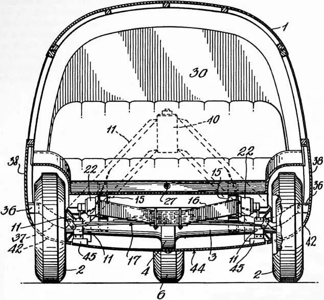 To this end the metal body covering below the sills 36 is inwardly curved at the sides, as
indicated at 42 and the middle space is closed in by a curved belly wall section marked 43 in
Figs. 1 and 3. This section 43 of the belly wall is a part of the body proper. Next in the rear of
the belly wall section 43 comes a continuation section 44 which is removably fastened to the
unsprung parts of the chassis, that is, to the differential casing and the legs of the sub-frame, the
forward attachment points being marked 45 and the rear points 46 (Fig. 3). Aft of this
section and extending to the end of the tail, the belly wall section 47 is fastened to
the incurved sides 42 of the body in some removable manner and this section is cut
with a circular hole 48A (Fig. 4) to accommodate the rear steering wheel. As thus
organized the belly wall is formed of three sections of which two are carried by the body
proper and the other intermediate section by the running gear. The sections meet
without contact in normally flush relation so as to provide a substantially smooth
belly from front to rear but it will be apparent that the edges will play past each
other according to the action of the springs. The gap may be covered or faired over
if desired to exclude entrance of air. While shown as made of metal the belly wall
may be made of fabric, if desired, in which case it may be continuous from end to
end.
To this end the metal body covering below the sills 36 is inwardly curved at the sides, as
indicated at 42 and the middle space is closed in by a curved belly wall section marked 43 in
Figs. 1 and 3. This section 43 of the belly wall is a part of the body proper. Next in the rear of
the belly wall section 43 comes a continuation section 44 which is removably fastened to the
unsprung parts of the chassis, that is, to the differential casing and the legs of the sub-frame, the
forward attachment points being marked 45 and the rear points 46 (Fig. 3). Aft of this
section and extending to the end of the tail, the belly wall section 47 is fastened to
the incurved sides 42 of the body in some removable manner and this section is cut
with a circular hole 48A (Fig. 4) to accommodate the rear steering wheel. As thus
organized the belly wall is formed of three sections of which two are carried by the body
proper and the other intermediate section by the running gear. The sections meet
without contact in normally flush relation so as to provide a substantially smooth
belly from front to rear but it will be apparent that the edges will play past each
other according to the action of the springs. The gap may be covered or faired over
if desired to exclude entrance of air. While shown as made of metal the belly wall
may be made of fabric, if desired, in which case it may be continuous from end to
end.
46 36
47 By thus enclosing the whole running gear, including as much of the wheels as consistent with road clearance in a properly streamline external contour, the advantage is gained that the rate of fuel consumption, as compared with conventional cars of equivalent size and weight, falls off rapidly as the speed is increased above about 10 m.p.h. being some 30% less at 30 miles and 50% less at about 50 miles, while within the overall dimensions of such conventional cars the volume of useful cabin space inside the streamline body is much increased, being practically doubled. All of the interior of the body forward of the drop-angle or bulkhead wall 30 constitutes the useful space for passenger or cargo, and due to the drop-angle the rear seat can extend the full width of the body over the sub-frame 11, as well as over the main frame 15 and with cars of standard tread gauge this provides a seat some 6 feet wide, long enough to serve as a bunk for sleeping purposes.
48 The forward overhang of the main frame 15 pitches upwards from the forward wheels and terminates at about the bumper level of conventional cars or slightly higher, the purpose of which, among other things, is to take any collision impact in the event of accident at a point well in advance of the front seat and to receive it on the main frame, so that the inertia of the engine fixed on the rear of that frame will be available to absorb the impact, as is the case in conventional cars having the engine in front.
49 Steering is done by a hand-wheel 48 mounted at a convenient angle in front of one of the forward seats and according to this invention its connections to the steering head 9 provide for a maximum variation of steering angle of at least about 160° and in any event over 100°. With the traction wheels located at one third the body length abaft the front end, such range of steering angle affords a degree of maneuverability not heretofore attained in automobiles. In the present case the steering system includes a windlass contained in a case 50 with cables 51 trained over sheaves on the chassis or sub-frame and attached to the ends of the sprocket chain 52 of a full circular sprocket wheel 53 which is fixed to and below the steering head 9. By the use of a full circular sprocket
50 wheel the same constant degree of tautness is kept in the cables for every steering angle, without which the steering would be erratic and unsatisfactory. A keeper or guard 54 is provided about the sprocket wheel rim to guide and retain the chain thereon. This keeper is fixed by rigid bracket arms to the steering head barrel 10 of the sub-frame 11, directly over the steering-wheel mudguard 55 which turns with the steering head 9. The lugs 56 (Fig. 4) on the ends of the sprocket chain serve to limit the steering angle by their abutment against the ends of the keeper 54. They limit the steering range to something less than 180° of arc. The gear ratio of the steering system is about 30 to 1 and in order to make quick changes through large angles, the hand-wheel 48 is provided with a crank knob 57 by which it may be easily spun.
51 While rear-steering greatly improves maneuverability as compared to conventional cars, and particularly with the traction wheels in the position described, it is apt to give rise to a tendency to skid when braking or rounding corners. This however is eliminated according to this invention by the distribution of the weight and the location of the center of gravity of the vehicle. It is found that such center should be forward of the mid-point of the wheel base and must not in fact be located further aft from the forward wheel axis than a distance equal to about 40% of the wheel base length. The importance of the pronounced forward body overhang will now be apparent, since even with the engine in the rear it brings the center of gravity to the position of maximum safety against skidding. In the car taken for illustration, the center of gravity is about 20% aft of the front axle, some 75% of the total weight being on the two forward wheels, and this location of the gravity center is preferred. The normal loading of the vehicle will not appreciably shift it. Also specially contributing to the maneuverability and ease of handling generally is the fact that the traction center as well as the gravity center are both located in the same general position, forward of the center point of the wheel base and that this position also substantially coincides with what may be called the streamline center of the body which may be taken as its center of volume or the center of area of its axial section. This center is indicated roughly in Fig. 3 by the small circle 58; the gravity center is lower down and the traction center of course coincides with the axis of the front wheels. The consequences of the grouping of these important centers in the same general forward location are reflected in the structural economy of the vehicle and become obvious on comparison with the action of conventional cars and especially those which have their fraction center rearward of the mid-point of the wheel base.
52 A view to the rear is afforded to the driver through a water-tight roof window 59 and an exterior inclined mirror 60 mounted on the roof at its highest point and within a rearward open hood or fairing 61 to avoid wind resistance and also shelter the mirror from the weather. The mirror may be viewed through the window and by reason of its position at the highest point gives unobstructed vision to the rear through a wide arc. This makes it easy for the driver to avoid swinging the tail of the vehicle so far to the outside when turning a comer, as to collide with adjacent cars or objects. To the same end the invention contemplates as an additional safeguard, useful in the case of drivers unaccustomed to rear-steered vehicles, a warning device of some kind which will announce the fact whenever the driver turns the rear wheel to such an angle as might be likely to result in a sideswipe. This may take any suitable form and as shown herein consists
53 FIGURE 6
55 38
56 FIGURE 8
59 FIGURE 9
60 of a wiper button 63 (Fig. 4) fastened to the steel steering cable 51 and adapted to contact with either of two electrically insulated terminal plates 64 mounted on a cross bar 65 and connected in circuit with a buzzer or the like 66. Whenever the rear wheel reaches or passes the angle which will run it outside of the tracks of the forward wheels, the signal is given and the driver’s attention is thereby called to the need of caution in the event there should be an adjacent object in position to be sideswiped. When operating within the limits represented by the two terminal plates, the driver may handle the car without concern for side collisions more than with ordinary automobiles. Instead of an audible signal any other device may be employed which will guard against involuntarily exceeding the normal range of steering angle.
61 A brake pedal is indicated at 62 but the braking system has been omitted; it may be applied to all three wheels, if desired, but braking on the two forward wheels alone has been found sufficient with the weight distribution as described.
62 While the various features of this invention have been above described as mutually combined and cooperating in a single structure which is rear-steered, it is to be understood and will be apparent that there is no intention
63 to limit this patent to such single combination inasmuch as certain subcombinations set forth in the claims obviously have important uses in independent relations.