
24 FLOATABLE BREAKWATER (1975)
2U.S. PATENT—3,863,455
3 PATENTED—FEBRUARY 4, 1975
4 There are many, many islands around the world that would be happily inhabited had they harbors. It is a question of whether the direction of the wind means that boats left at moorings on what would be the lee side of the island may, a few hours later, be on the windward side. Breakwaters consisting of rock or masonry cost vast amounts of money. I began to realize that the inertia of water itself, if trapped, could serve as a breakwater. In the last few decades, large rubber tubes ten or twenty feet in diameter have been filled with water, and have served very effectively as dams in rivers. I saw that there was a possibility that the mass inertia of trapped-water dams would lift with the approaching waves, and that the elevated water could be made to flow 90° to serve as a propellant of the water’s motion to generate power. So I undertook to produce such floating breakwaters and found that they work successfully.
5 UNITED STATES PATENT OFFICE
6 FLOATABLE BREAKWATER
7 The present invention relates to breakwaters and, more particularly, to a floatable breakwater.
8 The use of breakwaters to shelter selected bodies of water, such as harbors, has been long known. Such breakwaters are generally permanent in construction and are disposed in the water at such a depth so as to have an attenuating action upon the waves. Various forms of floating breakwaters have also been proposed in an attempt to provide a less expensive and relatively temporary breakwater construction. Such floating breakwaters are generally intended to be constructed at a central location and then towed into position at which point they are suitably anchored. However, it has been found that such floating breakwaters are generally unsatisfactory since they are relatively complicated in structure so as to be expensive to manufacture and do not truly fulfill then- function of effectively diminishing wave action so as to protect a harbor or the like.
9 It is known that the vertical motion of a wave is caused by a substantially elliptical movement of particles of water. An effective breakwater, floating or anchored to the bottom, must have a structure which effectively breaks up this elliptical movement of the water particles.
10 One of the objects of this invention is to provide an improved floatable breakwater.
11 Another one of the objects of this invention is to provide a floating breakwater which is substantially filled with water which effectively breaks up the wave motion.
12  According to one of the aspects of this invention, a floatable breakwater may comprise a
flexible open-ended tubular envelope enclosing a plurality of axially spaced buoyant annular
members or rings therein. The rings are movable axially with respect to each other while
supporting the envelope so that the movement of the envelope creates an accordion effect. Means
are connected to the open ends of the envelope for anchoring each end of the envelope. The
breakwater is positioned in the water with its longitudinal axis perpendicular to the direction of
the wave movement and is floating at such a depth that the breakwater will be substantially
filled with water. The filled envelope is expandable and contractable axially because of
the relative movement of the rings therein when the breakwater is acted upon by the
waves.
According to one of the aspects of this invention, a floatable breakwater may comprise a
flexible open-ended tubular envelope enclosing a plurality of axially spaced buoyant annular
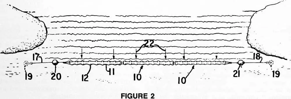
members or rings therein. The rings are movable axially with respect to each other while
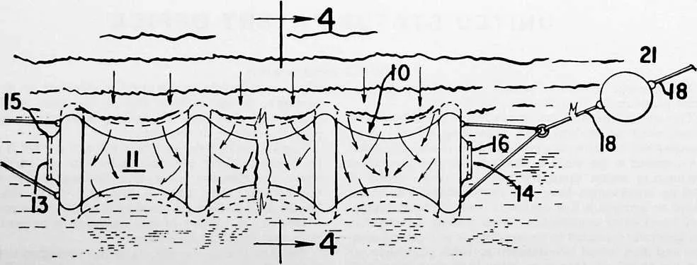
supporting the envelope so that the movement of the envelope creates an accordion effect. Means
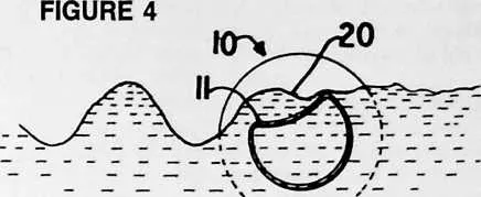
are connected to the open ends of the envelope for anchoring each end of the envelope. The
breakwater is positioned in the water with its longitudinal axis perpendicular to the direction of
the wave movement and is floating at such a depth that the breakwater will be substantially
filled with water. The filled envelope is expandable and contractable axially because of
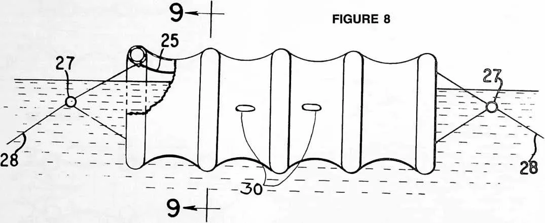
the relative movement of the rings therein when the breakwater is acted upon by the
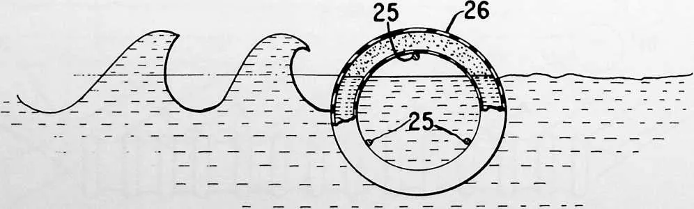
waves.
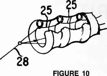
13 270
14 The ends of the envelope may be provided with a suitable drawstring-like attachment which can restrict the opening in the ends of the tubular member when it is filled with water and control flow of water therethrough.
15 Other objects and advantages of the present invention
16 FIGURE 3
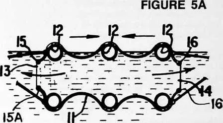
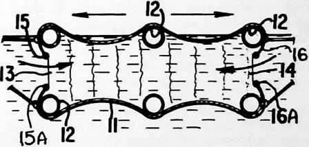
19 FIGURE 5B
20 will become apparent upon reference to the accompanying description and drawings which are merely exemplary.
21 In the drawings:
22 Fig. 1 is a longitudinal vertical view of one form of the breakwater made in accordance with the present invention and anchored in position in the water;
23 Fig. 2 is a top plan view of the breakwater shown in Fig. 1;
24 Fig. 3 is a fragmentary top view of the breakwater of Figs. 1 and 2;
25 Fig. 4 is a schematic sectional view taken along the line 4--4 of Fig. 3;
26 Figs. 5A and 5B are schematic side views of the invention showing the manners of operation;
27 Fig. 6 is a top plan view of the breakwater showing waves acting on the breakwater in a direction angularly disposed to the central axis;
28 Fig. 7 is a vertical view of Fig. 6 showing the action of the waves thereon;
29 Fig. 8 is a vertical view of a breakwater with a portion broken away to show an alternate form of securing means;
30 Fig. 9 is a sectional view taken along the line 9--9 of Fig. 8; and
31 Fig. 10 is a perspective view of the form shown in Figs. 8 and 9.
32 Proceeding next to the drawings wherein like reference symbols indicate the same parts throughout the various views, a specific embodiment of the present invention will be described in detail.
33 According to the present invention, the floatable breakwater is indicated generally at 10 which comprises a flexible open-ended tubular envelope 11 supported on a plurality of buoyant rings or annular members 12. The envelope 11 is formed of a relatively strong fabric or synthetic plastic material and is mounted upon the rings 12 so that the rings are capable of a relative axial movement between each other. The movement of rings 12 toward and away from each other creates an accordion-like effect in the surface of the envelope.
34 Rings 12 may be formed of a suitable water-buoyant material or construction and may comprise tubes from the tires of motor vehicles, such as automobiles, trucks or tractors. The material for the envelope 12 may be a transparent plastic material so that the motion of the water within the breakwater can be observed.
35 The ends 13 and 14 of the tubular envelope are both open, and each end has attached thereto drawstring-like arrangements 15, 16, comprising a valve-like closure with
36 drawstrings 15A, 16A, such as resilient lines adjacent the inner peripheral edge of the closure. As water runs in or out, it will cause the drawstring in the inner periphery of the opening to tend to open, the extent of the opening depending upon the velocity or rate of volume flow. It is also possible to arrange the drawstrings so as to operate in the opposite direction, i.e., to attach the anchor cables
37 FIGURE 6
39 17 or 18 to the drawstring (not shown) so that it will pull closed. Anchoring cable or cables 17 and 18 are connected to the ends of the envelope and to suitable means such as anchors 19 as shown in Fig. 1. It should be evident that by use of an anchor of the type illustrated, that the breakwater can be readily moved to another location.
40 Suitable water buoys of buoyant material may be attached at 20 and 21. The buoy material may comprise cork or foamed plastic as known in the art.
41 In operation, the breakwater can be constructed elsewhere and transported to its point of use. The breakwater is anchored within the water so that its longitudinal
42 FIGURE 9
45 axis is perpendicular to the direction of the wave movement as indicated by the arrows 22 in Fig. 2. There is sufficient flotation in the breakwater so that when it becomes substantially filled with water, as can be seen in Fig. 1, it will float with preferably a portion of the breakwater protruding above the surface of the water.
46 When waves hit the breakwater, they will cause the breakwater to move in the direction of the waves. By positioning the breakwater as shown in Fig. 1, the waves will hit upon the top of the breakwater and the force thereof will be distributed along the entire length of the breakwater.
47 It has been found that for effective operation, the rings should be positioned a distance apart which is substantially equivalent to the diameter of the respective rings. The breakwater can be made in 50-foot and longer sections, depending upon the intended use.
48 Fig. 3 illustrates movement of the breakwater in the direction of the waves as it is hit by the waves. Figs. 5A and 5B show the accordion-like movement of the envelope 11.
49 Fig. 4 illustrates the manner in which a wave at 20 may change the shape of the envelope 11 and cause movement of the breakwater elements in an accordion-like fashion.
50 It has been found that it may be desirable to fill the tubes about two-thirds full of water so as to provide inertia. Waves of about one-half the overall height of the tube diameter will be broken.
51 The effect of breaking waves moving at an angle to the axis of the breakwater is shown in Figs. 6 and 7. The inert water mass captured by the sausage-like structure will convert water force into an attempt to lift and move at 180° in the case of Fig. 2 or at an angle (Fig. 6) to the impingement of the waves on the breakwater. The local caterpillar-like lifting of the elements will cause water to surge toward the ends whose flexible openings tend to valve the in and out flow so as to further dissipate energy.
52 Figs. 8, 9 and 10 show another means of anchoring the breakwater. The lines or cables 25 are fastened at spaced points to the rings 26 and then are led to a common connector 27. Liner or cables 28 then are connected to the anchoring means.
53 The force of the waves in lifting the large body of water enclosed in the envelope would result in water pouring out of the ends. Thus, the vertical impingement of force would be dissipated at 90° to the impinging waves.
54 Flap or check valves 30 (Fig. 1) could be used, if desired, to permit water to flow in at the center but prevent water going out at the center. Similarly, flap valves (not shown) would be provided on the outside of the ends which would let water go out easily but would not let water come in except at the center.
55 It is therefore apparent that the present invention discloses a floatable breakwater which effectively distributes the force of waves along its length and which is resilient so as to be somewhat compressible in response to the force of the waves. A resilient and compressible characteristic of the breakwater effectively dissipates the wave force while at the same time permits construction of the breakwater to be relatively light.
56 It will be understood that various details of construction and arrangement of parts may be made without departing from the spirit of the invention except as defined in the claims.