
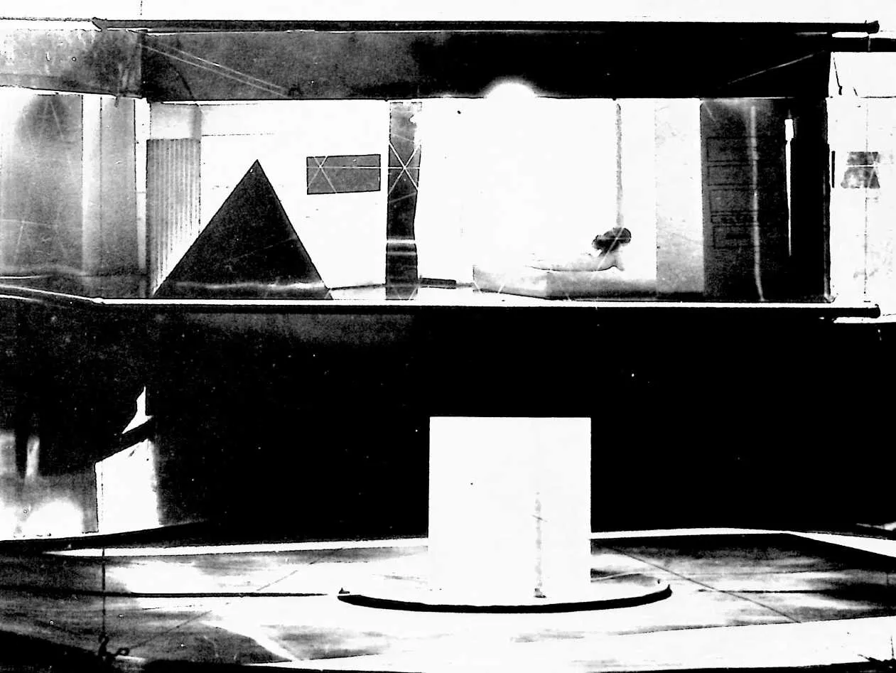
3 4D HOUSE (1928)
2WHEN, AFTER GETTING UP 240 Stockade
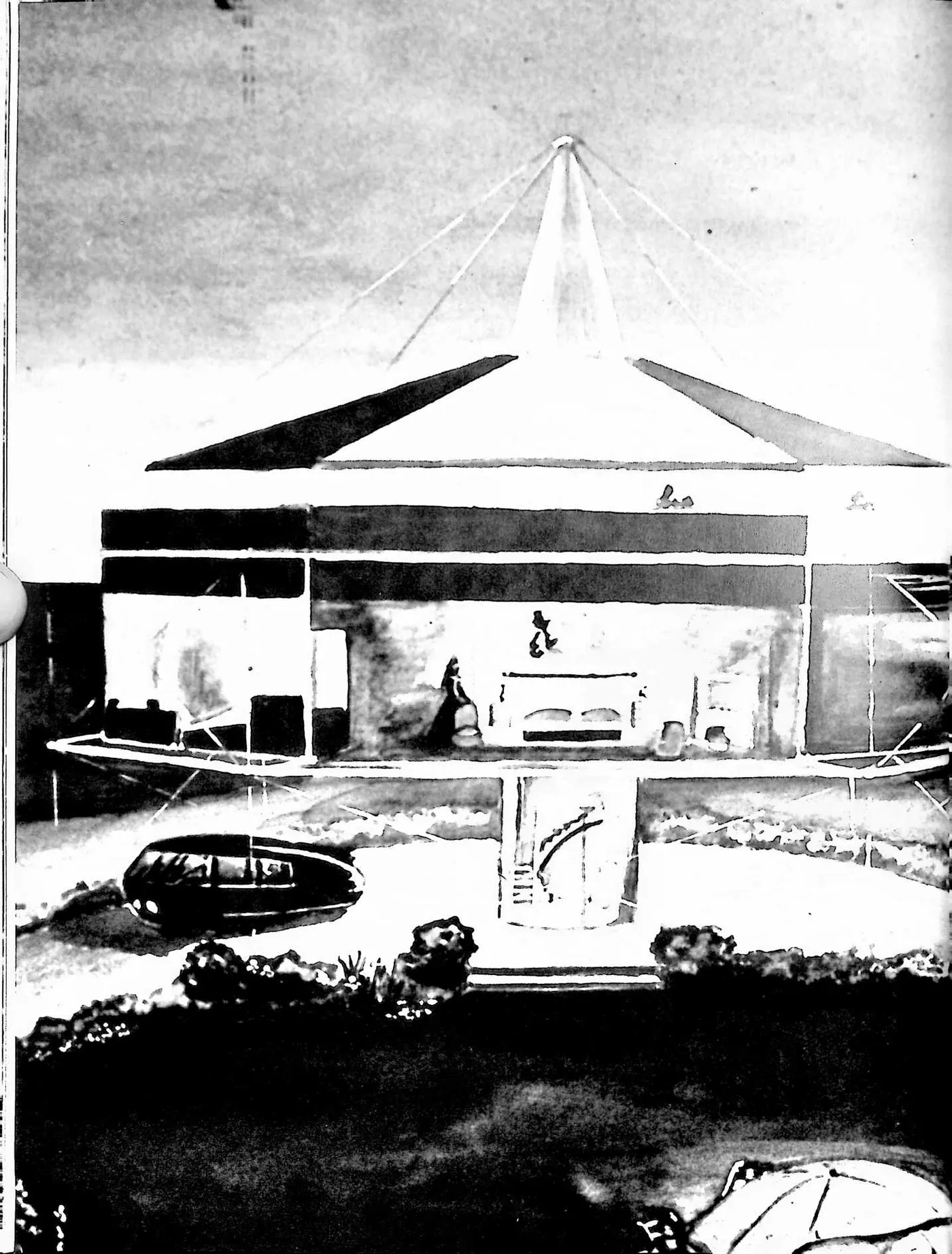
3 System houses in the Eastern half of the United States, I discovered that I could not make money by introducing so new a process into the building world, I became interested in how we might use aircraft technologies to produce dwelling machines for humanity. I was convinced by my experience in the building world that its activities were thousands of years behind the development of environment controlling for the sea and the sky. The 4D House was a consequence of my attempt to bring that advanced technology to bear on human environment controlling. I was producing tensionally cohered structures, and the 4D House was the result. My patent attorney felt that it would be much more convincing to the patent examiners if the same principles were employed but resulted in a rectilinear structure of conventional appearance. While the patent application embodied all the principles of the 4D House, it looked like a conventional house.
4 I knew very little about the world of patenting. In the case of my first two patents, the joint one with my father-in-law and mine for the manufacturing process, all the work was done by my patent attorney, who did not consult with me after the first disclosure. It is the formal procedure of attorneys dealing with the U.S. patent office to file applications for patents that first make a philosophical disclosure of the state of the art in which the invention is operative, then carefully describe the invention with accompanying drawings, then list a series of claims of what the inventor feels is the most economical statement of that which he feels is his unique invention. Then after the list of claims is filed, the patent office examiner sends back what is called the first rejection, rejecting a number of the claims but allowing one or two. The attorney and the inventor have the opportunity to make two more resubmissions of the stated claims, hoping to restate them acceptably to the examiners. The examiner indicates which of the claims might be restated in a final submission. In all, there are four such exchanges between the claiming inventor and the patent examiner. The patent attorney I had for the 4D House changed partnership and moved out of town. He did not tell me that the first rejection by the patent office was anything but a rejection. I did not know that subsequent resubmission of the patent was possible; I just assumed it was a final rejection and let it go. I knew I had a filing in the patent office of the invention and that it would serve as a first disclosure of my discovery from a scientific viewpoint.
6 THE 4D HOUSE
7 My invention relates to buildings and the erection thereof and includes among its objects and advantages the application of mass-production methods facilitated by changes in the building itself of such a nature as to make its completed parts capable of convenient transportation.
8 In the accompanying drawings:
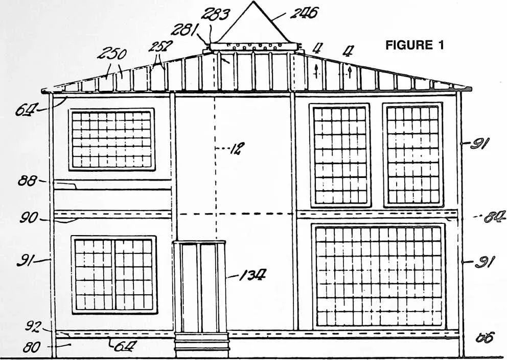
9 Fig. 1 is a front elevation of a two-story house according to the invention.
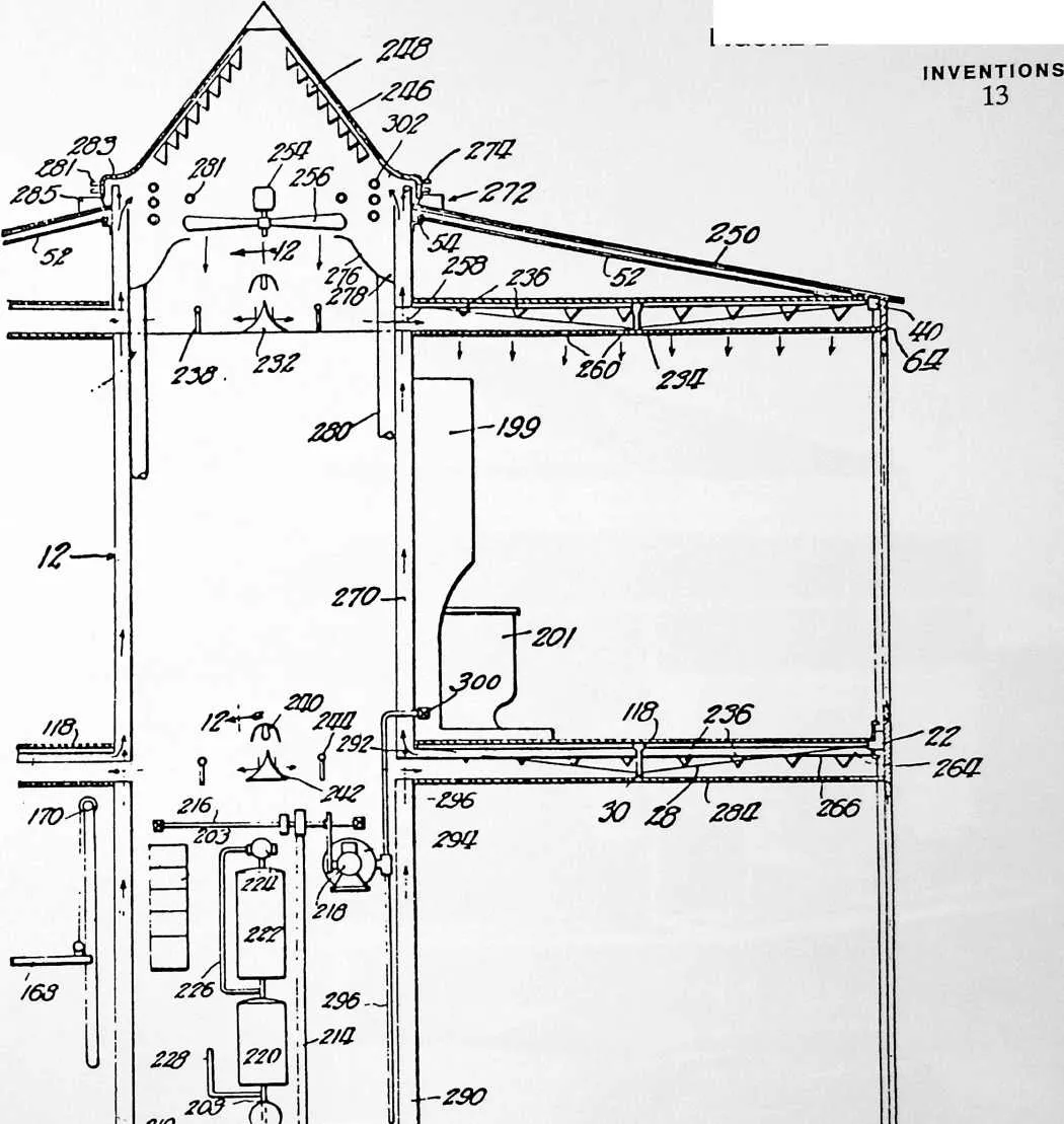
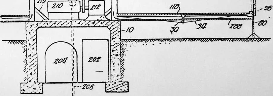
10 Fig. 2 is a central sectional view to the same house.
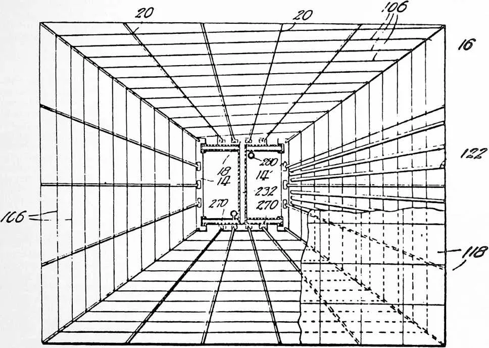
11 Fig. 3 is a plan view of the framework supporting the second floor.
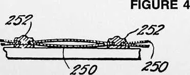
12 Fig. 4 is a detail section on line 4--4 of Fig. 1.
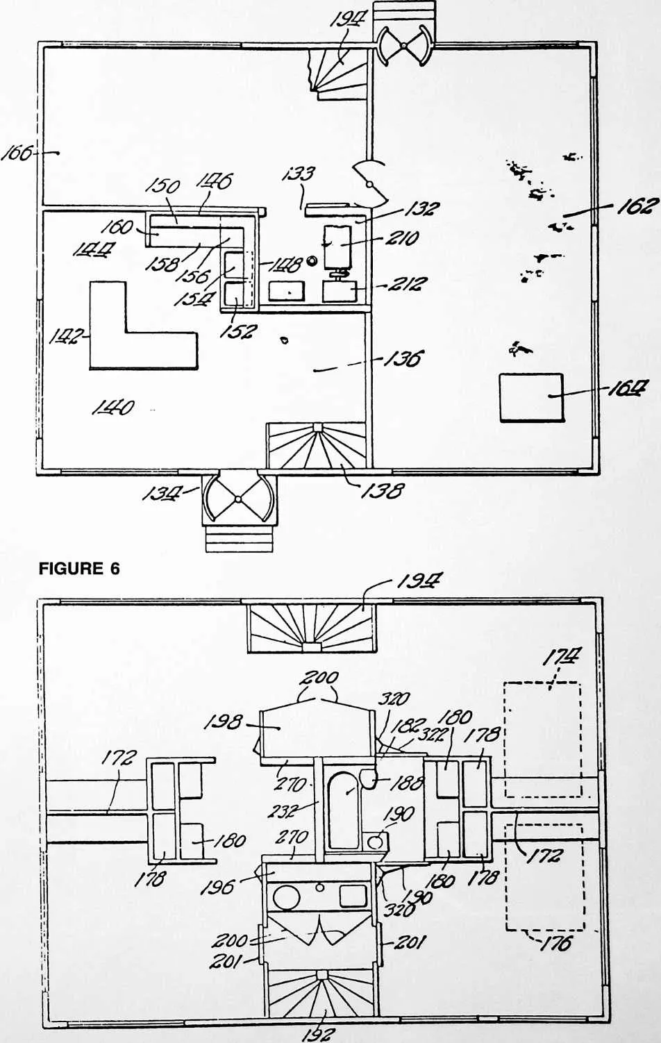
13 Fig. 5 is a floor plan of the first floor of the house.
14 Fig. 6 is a plan of the second floor of the house.
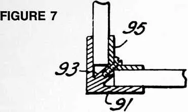
15 Fig. 7 is a detail section indicating one method of assembling a comer joint between the panels forming the outside wall.
16 Fig. 8 is a vertical section of the outer edge of the ceiling of second floor and roof.
17 Fig. 9 is a similar section of the outer edge of the floor of the second floor.
18 Fig. 10 is a similar section of the outer edge of the floor of the first floor.
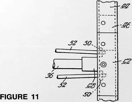
19 Fig. 11 is a section on line 11--11 of Fig. 8, chiefly in plan view.
20 Fig. 12 is a section on line 12--12 of Fig. 10.
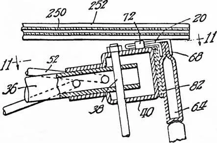
21 Fig. 13 is a vertical section of the partition forming the ceiling of the first story and the floor of the second story.
22 Fig. 14 is a vertical section of the central column in a plane at right angles to that of Fig. 2.
23 Fig. 15 is a section on line 15--15 of Fig. 13.
24 Fig. 16 is a side elevation.
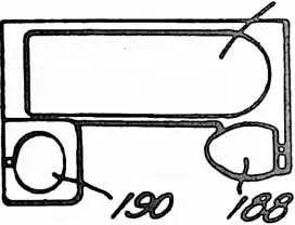
25 Fig. 17 is a plan view of a unitary one-piece bathroom.
26 Fig. 18 is a section of a floor construction.
27 Fig. 19 is a section of a construction for an inside partition.
28 Fig. 20 is a section of a construction for an outside wall.
29 •Application abandoned by Buckminster Fuller, leaving prior art evidence in patent office files.
30 FIGURE 2
35 Fig. 21 is an enlarged section through the outside connection of the ventilating system.
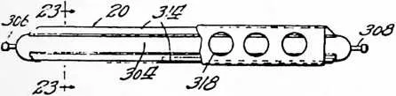
36 Fig. 22 is a side elevation of an improved type of beam.
37 Fig. 23 is a section on line 23--23 of Fig. 22.
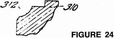
38 Fig. 24 is a section of a fitting for the end of a beam of Fig. 22.
39 Fig. 25 is a detail horizontal section through a vertical wall structure.
40 FOUNDATION
41 Referring now to Figs. 1 and 2 it will be seen that in the embodiment of a building according to the invention selected for illustration, the only foundation required is a central concrete housing or caisson 10 penetrating only a short distance below the surface of the ground and requiring a relatively negligible amount of excavation before pouring.
42 SUPPORT
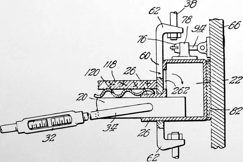
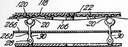
43 This caisson is surmounted by a central mast indicated as a whole by the reference character 12. At the level of each floor or ceiling, this mast is the center of a plurality of radiating members in the form of load-carrying beams supported at both ends. Referring to Fig. 3, which shows the supporting framework for the second floor in plan view, the end plates 14 are each provided with five receiving sockets for the metal tubes 16 radiating to the ends, and the similar side plates 18 carry the sockets for four similar metal tubes 20 radiating to the sides of the house. The tubes 16 and 20 are braced and united at their outer ends by a peripheral rim 22 in the form of a tube having openings for receiving the tubes 16 and 20. These openings are elongated as indicated at 24 in Fig. 12 to accommodate tubes entering at various angles, and a short lip or lug 26 projects from the edge of the hole both above and below the tube 20 to provide a better bearing surface. Each tube is braced and stiffened by a tension rod 28 held in spaced relation at the center of the span by a strut 30. This tension member may be connected by suitable turnbuckles 32 to a U-shaped clevis 34 passing through a transverse bore in the end of tube 20.
44 The frame at the level of the ceiling for the second floor differs from that just described in that the tube 36 may have much thicker walls because it carries a heavier load. It also extends in to receive the tie-rod 38 in a vertical bore. (See Fig. 8.) The tie-rod 38 not only brings up the weight load from the first and second floors but anchors the rod 36 against endwise movement with respect to the peripheral rim 40. The rim 40 differs from the rim 22 in receiving the rods 36 on its horizontal center line, and in having a separate cast section 42 where it receives the rod 36 fastened in alignment with adjacent portions 44 by a snugly fitted inserted plug 46 at each end of the casting. The casting carries a short tubular portion 48 receiving the tube 36 and 50 on either side of this tubular portion, affording connections for relatively heavy tension rods 52 connected at 54 to the central column.
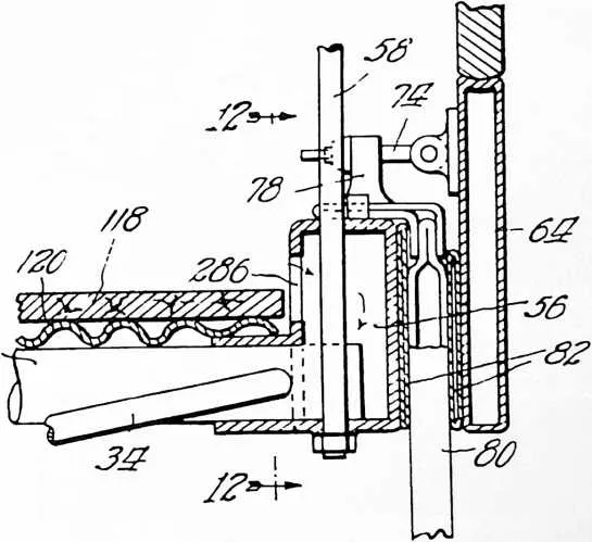
45 The frame at the level of the first floor may be identical with that at the level of the second floor except that the rim 56 is somewhat narrower in radial dimension to accommodate a different side wall construction. It is also vertically apertured where it receives each bar 20 to receive the lower end of a tie-rod 58 passing through the rim and also through a vertical bore in the end of the rod 20. The upper end of the tie-rod 58 is connected through to the lower end of the tie-rod 38 by a casting 60 having hooks 62 through which the ends of the tie-rods pass. It will be apparent that the weight load on all the beams at their inner travels directly down the column 12 to the caisson 10. A portion of the floor load from the first floor will be carried up through tie-rods 58, through the casting 60, through the tie-rods 38 to the end of the cantilever truss bound by beams 36 and tension rods 52. A portion of the floor load on the second floor will be carried by the casting 60 and up through the tie-rods 38 to the end of the truss formed by the tension members 52 and the beams 36. It will thus be apparent that the entire weight of the house and its contents may be supported by the central caisson 10. short studs 72 along the upper edge of the rim 40. By tipping the panel outward from the position shown in Figs. 8, 9 and 10 the studs 72 may be readily slipped into the holes and the panel is then permitted to swing down to the position shown.
46 At the second-floor level the panel is held against outward movement by a simple tie-bolt 74 and wing nut 76, taking over an anchor 78 on the rim frame for the second floor.
47 FIGURE 3
49 SIDE WALLS
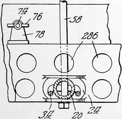
50 The side walls illustrated in Figs. 1, 2, 8, 9 and 10 comprise flat thin panels each in the form of a sheet metal grill 64 with cross pieces about one foot apart and insulating and protecting panels 66 inserted in each opening. Where the panels are transparent this amounts to a window structure. It will be obvious that they may be made translucent or that they may be opaque and of a color identical with the metal frame so as to present a uniform appearance to the eye.
51 Figs. 8, 9 and 10 are sections in a vertical plane just to the right of the sliding double door in Fig. 1. Over this portion of the front wall of the house a single panel is mounted. The edge of the sheet-metal frame is crimped together at 68 and spot-welded to an edging 70 having a plurality of apertures to enable it to take over a set of
52 At the level of the first floor I first mount an additional panel 80 on the sill 56 in precisely the same way as the main panel is mounted on the sill 40. The panel 80 extends downward a few feet and its edge may enter the ground for appearance’s sake and to keep animals out of
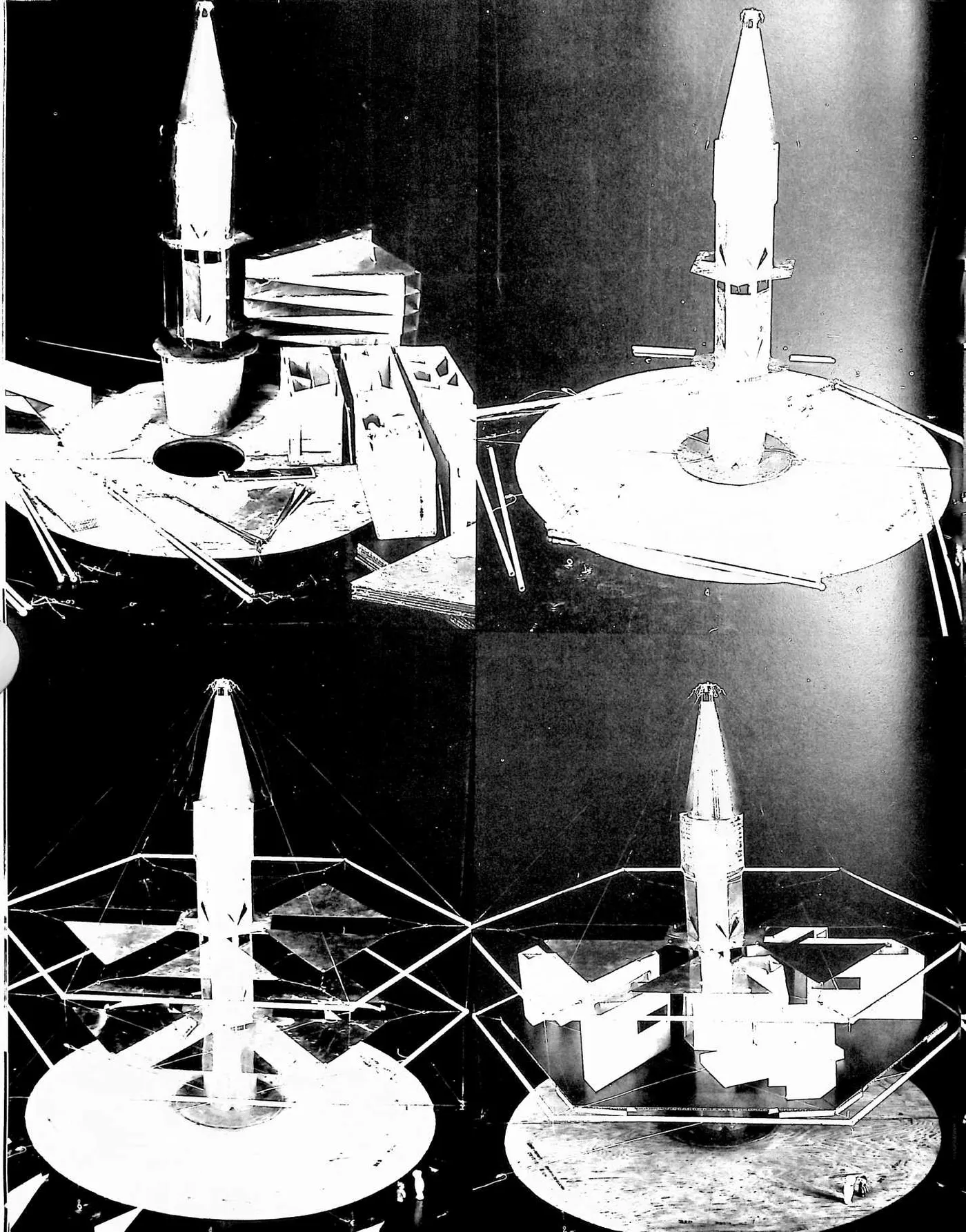
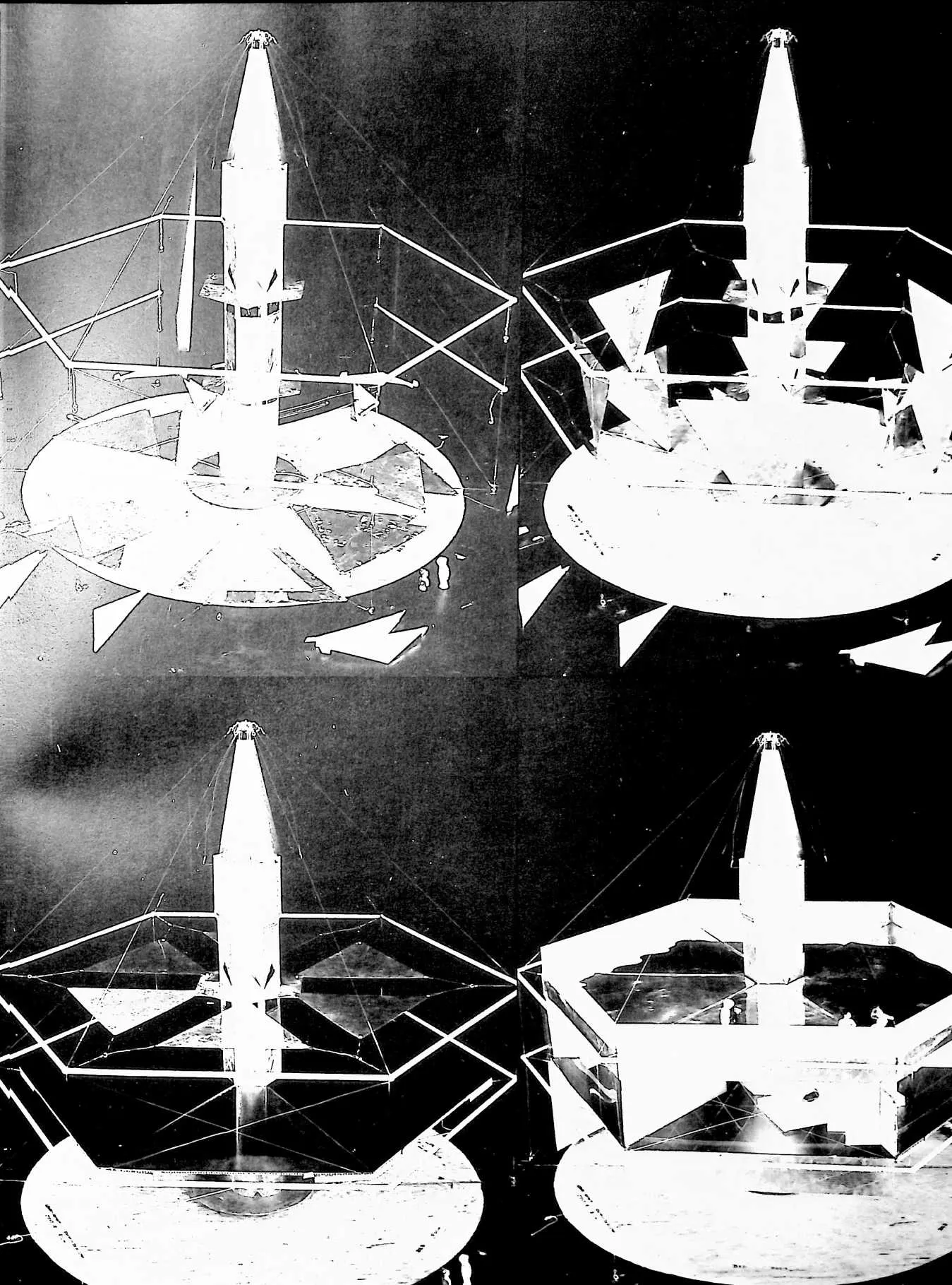
58 the space between the first floor and the ground. It carries no weight. The lower edge of the main panel is connected to the sill 56 by additional tie-bolts 74 precisely as at the second floor. Between each panel and the members against which it rests, I interpose a packing. I have the panel for the dining room or grille having its lower edge at 92. Such a construction permits complete removal of the panel terminating at 88 in warm weather, leaving this upstairs room open to the air and enclosed by a railing made up of the panel with its lower edge at 90.
59 The adjacent edges of the panels may be simply battened together. In Fig. 17 I have illustrated a corner batten comprising an outer strip 91 with a central rib 93 to receive the fastening screws for the inner strip 95.
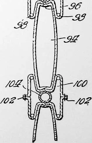
60 The side wall unit illustrated in Fig. 20 has panels 94 differing from the panels 66 in having their edges concave as at 96. Each pane or panel 94 is enclosed in a fabric edging drawn in around wire hoops 98 on each side and then out again, much as a piece of fabric for embroidery is drawn in a stretching frame. The free edges of this fabric edging 100 may be used to tie each pane to the adja-
62 FIGURE 8
63 illustrated flat strips of pneumatic tubing 82 laid in place between the sill 40 and the upper edge of the main panel, between the sill 22 and the middle portion of the main panel, between the sill 56 and the upper edge of panel 80, and between the upper edge of panel 80 and the lower edge of the main panel. After the parts are in place, inflation of the packing will clamp everything firmly together.
64 At the right side of the house illustrated in Fig. 1, I show a second-story panel having its lower edge at 84 and a different first-story panel having its lower edge at 86. In this portion of the house the joint beside the sill 22 will be precisely analogous to the joint shown beside the sill 56 in Fig. 10.
65 At the left side of the house shown in Fig. 1, I have illustrated a separate window panel hanging from the sill 40 and having its lower edge at 88. The next unit is a short panel having its lower edge at 90 and below that is
66 FIGURE 9
68 cent panes by stitching the edges of the edging strips together as at 102. Before this is done pneumatic tubing 104 is laid between the opposing edges of the panes and connected to a suitable inflation valve. After a plurality of such panes have been united to form a large panel, the introduction of air under pressure into the tubing 104 will brace and stiffen the structure into a semi-rigid panel which can be mounted and fastened in place in the same way as the panel illustrated in Figs. 8, 9 and 10.
69 FLOORING
70 To build up a floor suitable for use I first run a mesh of tension wires 106 (see Fig. 3) over the load-carrying beams 16 and 20. These wires may be made up of a single strand arranged in a spiral. Above these wires (see Fig. 18) I stretch a sheet of canvas or heavy tarpaulin 108. A plurality of pneumatic floor mats are provided with a rality of rubber tubes 124 encased in a fabric sheathing 126 to form a unit not unlike the body protector wom by a baseball catcher. A flat and ornamental tapestry surface may be given to such a partition by enclosing the entire unit in a fabric bag having walls 128 of tapestry of such other material as may be desired for a proper decorative effect within the room. Obviously, where the partition subdivides two rooms of different kinds, the surfacing 128 may be of different sorts on opposite sides of the bag. Thus one side might be a light blue tapestry suitable for a bedroom, and the other side might be a white waterproof oilcloth or linoleum suitable for a bathroom wall. The sides of the bag may be brought together at the top and stitched to form a welt 130 by means of which the wall may be suspended in place.
71 In any surface I may secure a snug assembly by the instrumentalities illustrated in Fig. 25. The tightening
72 FIGURE 10
75 module of three feet in plan view. Thus an ordinary mat will be three feet square in plan view, although units six feet square or three feet by six or nine feet may readily be employed. The pneumatic mats illustrated are about one inch thick and hold to a flat shape by tension cords 110 suitably embedded in the rubber lining 112. The whole rubber unit is encased in a fabric sheet 114 of heavy canvas.
76 To build up the floor, the entire surface of the tarpaulin 108 is covered with mats and suitable rugs or matting 116 are laid on top of the pneumatic mats. This provides a floor surface ready to walk upon. In the construction of Fig. 15, the matting 118 is made up in units three feet square and laid over a corrugated metal panel 120 of the same size to make up a unit panel of flooring. The wires 106 are bowed to a catenary curve by laying strips 122 between the wires and the panels of flooring, and the positioning of the panels on top of the wires and strips completes the floor.
77 INSIDE PARTITIONS
78 The inside partitions between the rooms may be of construction identical with the panels of Fig. 8 or Fig. 20. I have illustrated a pneumatic partition made up of a plu-
79 FIGURE 13
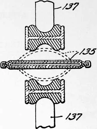
81 means comprises a pneumatic bladder 135 in a flexible protecting casing having the flat shape indicated in dotted lines before inflation. One or more of the vertical joints between adjacent panels 137 may have a tightener slipped in place. After the panels are set in place, the inflation of the tighteners will set up a snug gripping engagement at all the joints. By varying the inflation the dimensions of the joint may be varied. In this way, by using several tighteners standard units may be set into spaces just large enough to receive them, or expanded to fit properly in larger spaces.
82 FIGURE 12
86 FIRST-FLOOR PLAN
87 Referring now to Fig. 5,1 have indicated a central storage space for the power plant and service units at 132 on the first-floor level inside the column 12. Access to this space is from the garage through a door at 133. The revolving front 134 may open into a space at 136 serving as INVENTIONS a hallwaY and means of access to the front stairway 138.
88 qa This area may or may not be partitioned off from the
89 grille located at 140. For the grille I have indicated an L-shaped table 142 and a unitary kitchen unit 144.
90 graph, a television receiving set, and any other desired conveniences. I have indicated a garage space 166 where a car may be stored. The vertical distance between floors is such that additional storage space for trunks and the like may be made available by having a false floor 168 (see Fig. 2) movable vertically by means of hoists 170 in the garage. This can be lowered to provide easy and convenient access to trunks and the like supported thereby, and then raised to a sufficient height to afford ample clearance for the storage of a car beneath the same.

92 FIGURE 15
93 FIGURE 17
94 SECOND-FLOOR PLAN
95 Referring now to Fig. 6,1 have illustrated a second floor that may be made up to have four bedrooms and two baths. From an appropriately positioned load-carrying beam 36 I suspend a rigid partition 172. This partition forms part of a complete unit assembled as such at the
96 The kitchen unit may be assembled at a central point or factory, complete and ready for use except for connecting to local gas and water pipes, etc. It comprises a floor panel, two modules on each side, with vertical supporting surfaces at 146 and 148, which extend to the ceiling and carry the upper storage cabinet indicated at 150. At customary levels all the units necessary for complete kitchen or grille service are built into place. These may include an oven 152, stove unit 154, dishwashing machine 156, worktable 158 and sideboard 160.
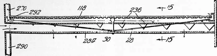
97 FIGURE 16
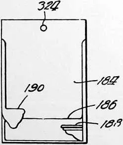
99 I have indicated a living room 162 extending all across one end of the house. In addition to the usual pieces of furniture, this room may be provided with a combined unit 164 including a radio receiving set, a motion picture machine, a Dictaphone, steel safe for valuables, a phonocentral point or factory. The unit includes two beds 174 and 176 foldable into a vertical position out of the way or out into the positions indicated in Fig. 6 for use. The partition also supports the wardrobes 178 and other suitable units 180, such as dressing tables facing the bathroom at 182. It will be noted that above the second-floor level the central mast changes from a box section to an H section providing the space at 182 inside the H into which may be set the bathroom unit indicated in Figs. 16 and 17. This is a one-piece unit including a side wall 184 extending to the ceiling level, a bathtub 186 beside the side wall, a toilet seat 188, and the lavatory 190. All this is preferably assembled with a special flooring unit extending out to the position indicated in dotted lines at 190 in Fig. 6 and sent out from the factory ready to be set in place, and when set in place ready for use except for connecting up piping. The space between the corner bedrooms at the front and rear of the house is occupied by the front stairway 138 and the rear stairway 194, both of which are semi-circular, and by utility units located at 196 and 198 with a hall between to afford means of connection between the bedrooms. Where a single family occupies the entire house, one of these units may be a laundry unit comprising a drier 199 (see Fig. 2) and complete washing and ironing equipment at 201, and the other might be a miniature carpenter shop or radio laboratory for the children. Where two families occupy one house both units may be laundry units. In connection with a laundry unit in such a location, I prefer to employ overhead rolling doors 200 in front of the utility unit and sliding doors 201 at each end of the passage across in front of the rolling door. These doors may be arranged
100 so that when they are both thrown open the laundry unit and the space in front of it constitute a separate enclosure shut off from the bedrooms on either side.
101 POWER AND SERVICE
102 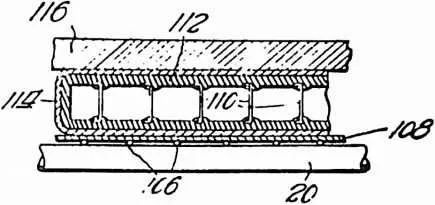 The central mast 12 is of a size that can readily be shipped and transported on a railroad
car or a motor truck. It has built into it at the central point or factory practically all the
equipment indicated in Fig. 2 except for some minor items such as the reflecting surfaces for the
lighting system and the liquid for the storage batteries 203, which might interfere
with handling during shipment. The preparation of the terrain involves only a very
little leveling and the installments of the caisson 10 with a fuel oil tank 202, a septic
tank 204, and a pipe connection at 206 running down to a well or to the city water
supply. The mast has built into it the upper section 208 and the piping and tanks
associated therewith. I have also indicated a diesel engine 210 direct-connected to an
electric generator 212 and connected by a belt 214 to a countershaft 216 from which
the air compressor 218 and any other desired power machinery equipment may be
driven. This unit is fastened into the mast by braces 219, and shipped out with the
mast.
The central mast 12 is of a size that can readily be shipped and transported on a railroad
car or a motor truck. It has built into it at the central point or factory practically all the
equipment indicated in Fig. 2 except for some minor items such as the reflecting surfaces for the
lighting system and the liquid for the storage batteries 203, which might interfere
with handling during shipment. The preparation of the terrain involves only a very
little leveling and the installments of the caisson 10 with a fuel oil tank 202, a septic
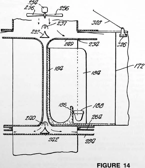
tank 204, and a pipe connection at 206 running down to a well or to the city water
supply. The mast has built into it the upper section 208 and the piping and tanks
associated therewith. I have also indicated a diesel engine 210 direct-connected to an
electric generator 212 and connected by a belt 214 to a countershaft 216 from which
the air compressor 218 and any other desired power machinery equipment may be
driven. This unit is fastened into the mast by braces 219, and shipped out with the
mast.
103 FIGURE 18
104 WATER
105 The single water inlet at 208 may be connected through at pump 219 and a water softener 220 and a heater 222 to a mixing valve 224 provided with a bypass 226 around the heater. The mixing valve may readily be connected to the bathroom unit to deliver water at any desired temperature for the bathtub and lavatory. A side tap at 228 may provide unsoftened water for drinking, air washing, and the toilets.
106 LIGHT
107 It will be noted at the outset that the roof and side walls disclosed may be constructed to admit many times the light now available in an ordinary dwelling. The artificial lighting system indicated includes a powerful central light 230 level with the ceiling of the second story just above a conical reflecting surface 232 shaped to reflect light horizontally just above the ceiling panels 234 of the second story. These ceiling panels are translucent or semi-transparent and above them I mount a series of reflectors 236, each reflector extending down a trifle lower than the one next it and nearer the source of light. In this way the flood of light emanating from the reflector 232 is distributed over the entire ceiling panel and sheds a diffusing light through the rooms below. Shutters 238 have been indicated for cutting off the light to any portion of the second floor, so that each room has its own selective light control. These shutters may be combined with colored glasses, making it possible to change the color and intensity of the illumination at will.
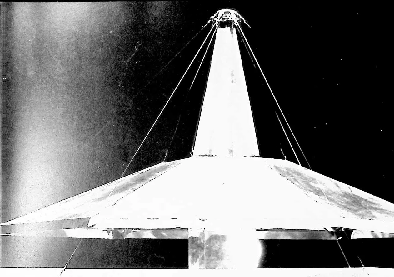
108 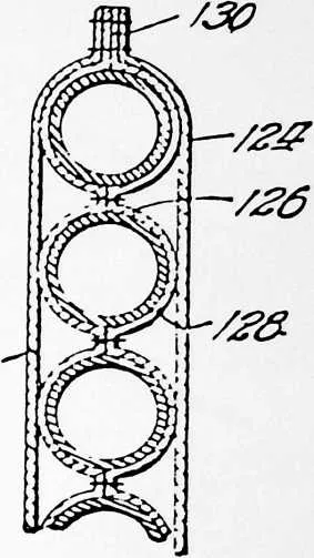 A similar central lighting unit including the light source 240, reflector 242 and
control-shutters 244 is provided at the level of the floor for the second story and the light is
distributed by reflectors 236 which may be identical in construction and function with those for
the upper story.
A similar central lighting unit including the light source 240, reflector 242 and
control-shutters 244 is provided at the level of the floor for the second story and the light is
distributed by reflectors 236 which may be identical in construction and function with those for
the upper story.
109 /Z?
110 FIGURE 19
111 The top of the central mast is surmounted by a cone 246 provided with a serrated lens structure 248 for focusing sunlight in the space immediately above the reflector 232 where a considerable amount of the same will be re-
112 FIGURE 20
115 fleeted out against the reflectors 236. A shutter 249 in the
116 FIGURE 21
117 FIGURE 22
118 ceiling of the bathroom may be removed to permit a flood of almost direct sunlight to shine directly in. The roof may be built of transparent vacuum panels 250 supported by battens 252 so that a flood of sunlight may pass
119 through and illuminate the translucent ceiling 234 of the entire upper story.
120 VENTILATION AND CLEANING
121 The house is provided with power means, indicated as an electric motor 254 driving a fan 256, for generating throughout the house.
122  The circulation for the upper story is from the fan downward to the level of the lighting
units 237 and 232 (which will be cooled by the circulation of air over them and incidentally
afford an appreciable amount of heat for the house) and then out through louvers 258 into the
space above the second-floor ceiling 234. From here it passes downwardly through a
large number of small apertures indicated at 260 in the form of a descending bank
or
The circulation for the upper story is from the fan downward to the level of the lighting
units 237 and 232 (which will be cooled by the circulation of air over them and incidentally
afford an appreciable amount of heat for the house) and then out through louvers 258 into the
space above the second-floor ceiling 234. From here it passes downwardly through a
large number of small apertures indicated at 260 in the form of a descending bank
or

125 I
126 slowly moving mass to the level of the floor. From the floor level it is withdrawn through the apertures 262 in the sill 22 (see Fig. 9) and passes back at 264 through a conduit defined by the flooring for the second floor and by a horizontal baffle or partition 266 separating the space between the ceiling for the first story and the floor for the second into two levels. The baffle or partition 266 may readily be held at the proper level by connections at 268 (see Fig. 15) with the struts 30. The air returning under the floor passes up at 270 through the double walls of the mast to the extreme top at 272, where it is deflected inwardly and returned to the suction side of the fan 256.
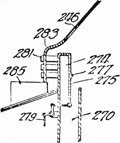
127 Additional air from outside may be mixed with the air circulating in the building at this point. Referring to Fig. 21, I have illustrated a box 274 mounted at the outer edge of the upper end of the passage 270. The lower edge of the box may be in the form of a flap 275 manually adjustable about the hinge 277 by control connections 279. Horizontal tubes 281 extend outward from the box 274 to discharge air into the outer atmosphere. The cone 246 is continued over the box 274 in the form of a shelter plate 283 through which the tubes 281 pass. The air ejected through the tubes 281 may be replaced by an influx through a suitable chemical air gas filter 285. This filter may operate under ordinary conditions to eliminate traces of sulfur dioxide, odors from stockyards, or other undesirable contamination in the air. It may also be constructed so as to be easily changed over to function as a protection against poison gas. The air entering through the filter passes upward around the tubes 281 and in between the box 274 and the cone 246 to the exhaust side of the fan.
128 The rotation produced by the fan 256 will throw such solid particles as may be brought up by the returning airstream to the outside of the baffle or dust guard 276 to accumulate in a pile at 278, from which the accumulation may be removed by flushing at infrequent intervals
130 FIGURE 23
131 FIGURE 25
132 through the outlets 280. In winter weather when the air is dry it may be moistened by the spray 281, which also washes down the accumulated dust.
133 The circulation for the lower story is identical in principle with that just described for the upper. The air from the pressure side of the fan 256 passes down the central portion of the H as indicated at 282 in Fig. 14 and then horizontally out between the baffle 264 and the ceiling 284 for the lower story. It leaves the rooms through the apertures 286 in the sill 56 and passes back under the flooring and above the lower baffle or cover 288 and upward at 290 to join the air returning from the second story at 292 (see Fig. 2). The lower cover 288 should have the same thermal insulation properties as the side wall panels.
135 It will be apparent that the floors of both the first and second stories are subject to a continuous removal of dust and dirt by the air passing out through the apertures 262 and 286. For cleaning I prefer to employ a pressure system. Referring to Fig. 2, it will be noted that the air tank 294 has been connected by piping 296 to an outlet 298 on the first floor and a similar outlet 300 on the second. These terminals may be quick detachable coupling units such as those employed by the Alemite and other systems for dispensing fluids, and the housewife may clean the floor or furniture simply by coupling a length of tubing to the nozzle of the air pressure connection and blowing all the dust and dirt on the floor through the apertures 262 and 286 to be carried up and deposited in the dust accumulators 276.
136 In cold weather it will be found most advantageous to add the necessary heat to the air circulation indicated at the top on the suction side of the fan 256. The lights at 238 and 240 may supply all or nearly all the heat necessary even in ordinary winter weather. I have indicated an auxiliary heating means in the form of a coil of piping 302 adapted to be connected with the exhaust pipe of the diesel engine 210, or with any suitable steam generator or the like.
137 In a dwelling intended for quick and easy transportation and erection and subsequent moving from place to place with relative great facility, the weight of the structure itself becomes a significant item. Referring to Fig. 2, I have illustrated a beam for use as one of the beams 16 and 20 of Fig. 3 or as part of the central mast in case the mast is a built-up structure. The beam comprises a tube 304 of relatively large diameter so as to get the metal as far as possible from the neutral axis. To avoid too large a cross section of metal, it may be necessary to make this tube with a very thin wall. I have illustrated a valve 306 by means of which the tube may be inflated with air at relatively high pressures. The tube may carry a relief valve 308 at the other end adapted to open when, as in the case of fire, some temperature rise raises the pressure above the bursting strength of the metal. The necessary load-carrying connections at the ends of the tube may be provided by metal heads 310 having sockets 312 shaped to fit the end of the tube.
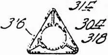
138 Where such a beam is to support flooring or carry the weight of a suspended partition, it may be provided with additional stiffening and attachment means in the form of radial fins 314 of which I have illustrated three in Fig. 23. The edges of these fins may be braced against buckling by thin sheet-metal shields 316 cut away as at 318 for lightness. Such units can be made materially lighter and easier to handle and ship than an ordinary beam or truss.
139 Another weight-saving expedient is indicated in Figs. 6 and 14. The floors of the utility units 196 and 198 have beveled shoulders at 320 to abut shoulders 322 on the bathroom units. All four units are hung on the mast 10, as by attachment means at 324 (see Fig. 16). The abutments at the bottom provide complete alignment means for the units independent of the mast. The partition 172 may abut the outer edges of the flooring of the bathroom units 182 and be supported primarily by a tension connection at 326 so that the weight of the partition 172 and associated parts will cause it to bear snugly against the bathroom unit. The concentrated load may be carried by an auxiliary tension member 328 running direct to the point of attachment 326.
140 Without further elaboration, the foregoing will so fully explain the gist of my invention that others may, by applying current knowledge, readily adapt the same for use under various conditions of service.