
9 DYMAXION HOUSE (WICHITA) (1946)
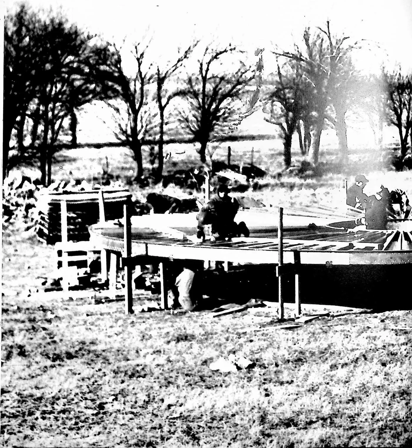
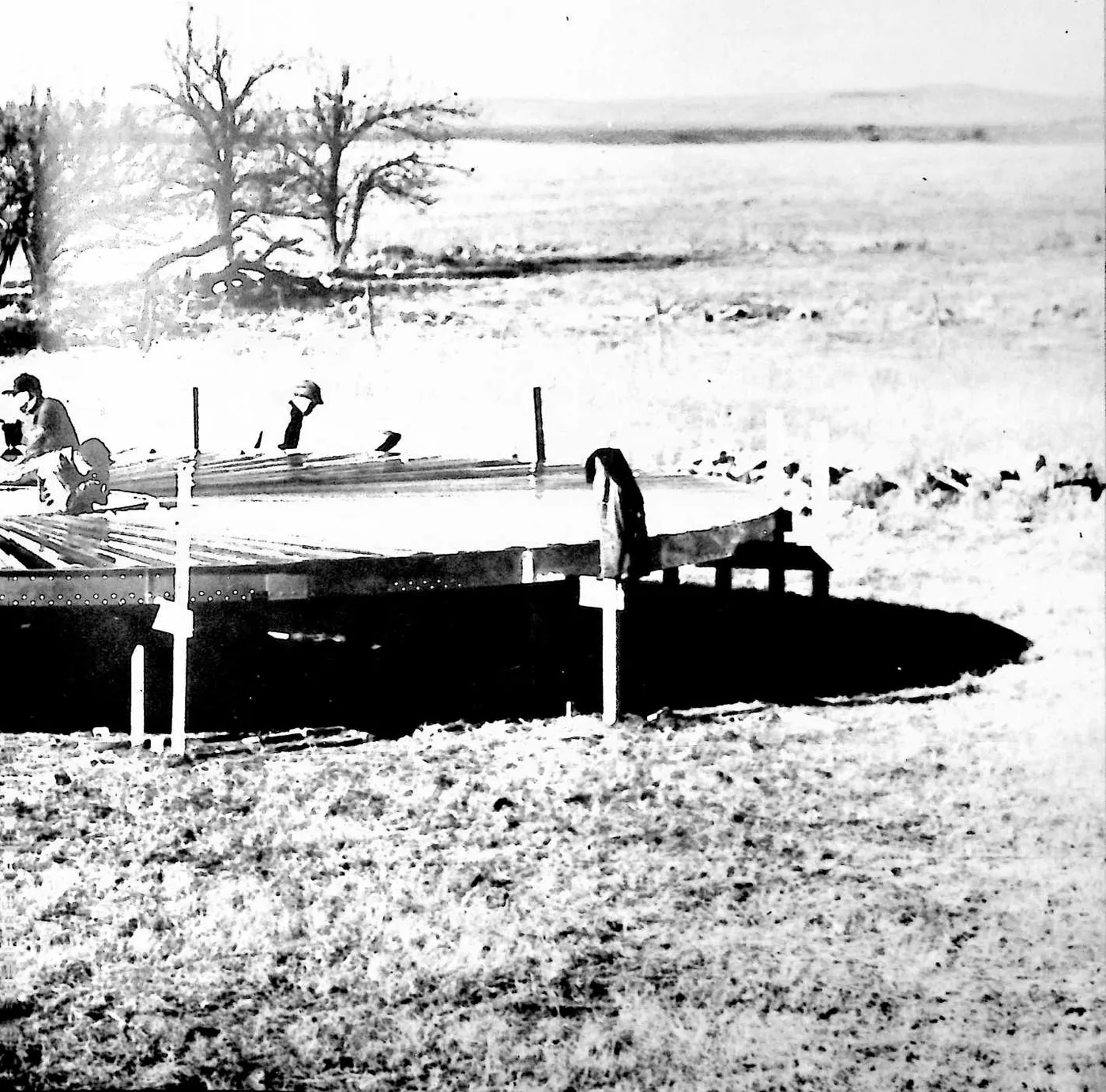
2BN 1944 THE AERONAUTICAL PRODUCTION division of the U.$. War Production Board and the U.S. Department of Labor became alarmed over 4he fact that they were being completely frustrated in their bomber, fighter, and auxiliary aircraft production because labor did not like the tour of Wichita, Kansas, and other longtime aircraft-production company towns of the West. These locations were proving so unsatisfactory to labor that labor was deserting these towns and was turning to other war production activities. In Wichita, Kansas, the vitally essential B-29 bomber was being produced, together with many other fighter and auxiliary craft. In 1944 the Wichita population doubled from 100,000 to 200,000. People were sleeping in three shifts in the same beds. Life was intolerable. The workers could see no future for aircraft production after the war (international flights and jets had not yet been developed). Workers by the thousands were quitting Wichita daily to find more comfortable war work elsewhere where postwar employment conditions would be more favorable. Labor leaders in Washington, D.C., recalled that I had been developing the Dymaxion House to be produced only by the most advanced aeronautical technology. The War Production Board and U.S. labor leaders asked me to go to Wichita and meet with the chief executive officer of Beech Aircraft, where they had the best labor relations. I did so and we produced my Dymaxion dwelling there. Finished, it weighed the three tons that I had estimated it would in 1927, in contrast to the 150-ton-volume, floor area, and techno-facilities equivalent one-family house produced by conventional building methods. In my book Grunch of Giants I relate what happened subsequently.
3 UNITED STATES PATENT OFFICE
4 This invention relates to houses, this term being comprehensively used to include shelters in the forms of dwellings for people, commercial establishments, schools, manufacturing plants, and, in general, for any purpose or things requiring shelter from the weather.
5 The primary object is to provide a house assembled
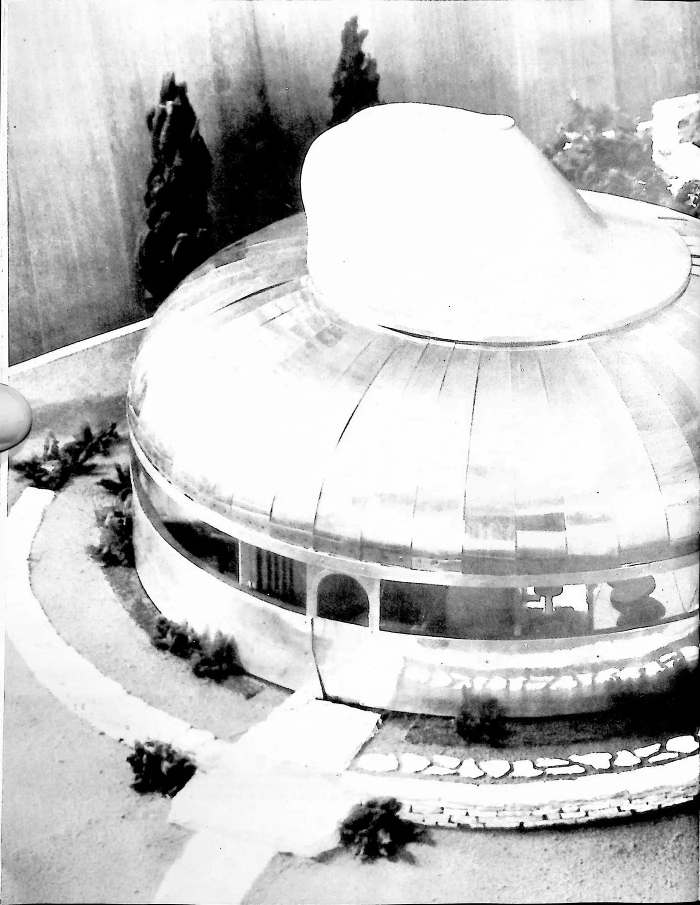
8 from parts having a total weight so light and capable of being grouped in a unit package so compactly as to make it economically practicable to manufacture and package the house in a factory and then to ship the packaged house from this factory to anywhere in this or foreign countries, together with the requirement that the assembled house must be capable of functioning adequately as a home for the average small family or, in general, as necessary to meet the requirements of sheltering constructions of comparable size. However, the principles of the invention are applicable to larger structures. These principles provide for a house that is not only economically competitive with conventional houses but which has many advantageous features unobtainable by any prior art construction methods.
9 A house intended as a home for a small family, which embodies specific examples of the principles of the present invention, is illustrated by the accompanying drawings in which:
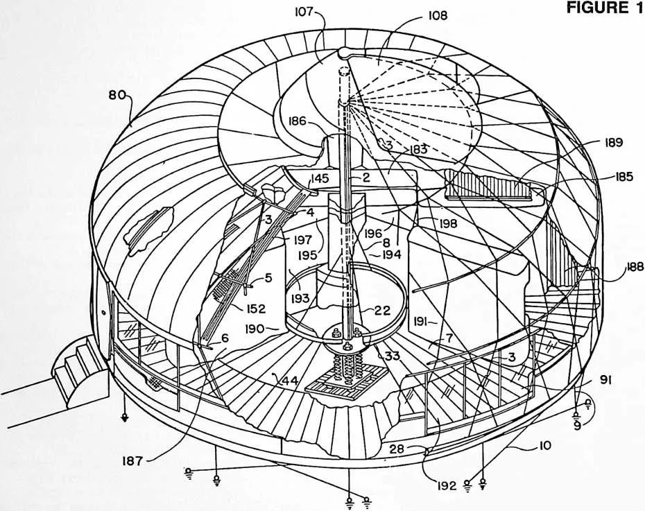
10 Fig. 1 is a perspective view having broken-away portions and showing the general construction of the house in its entirety;
11 Fig. 2 is a side view of the compression mast and footing;
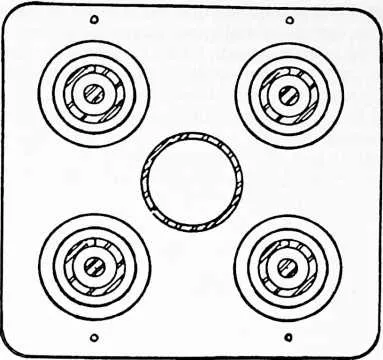
12 Fig. 3 is a cross section taken from the line 3--3 in Fig. 2;
13 Fig. 4 is a top view of the mast;
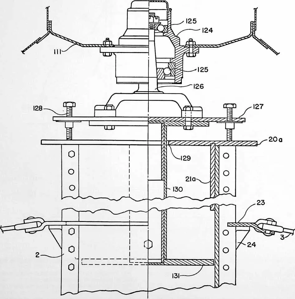
14 Fig. 5 is a partly sectioned side view of the top of the compression mast and including the rotative ventilator mounting;
15 Fig. 6 is a top view of one of the compression rings;
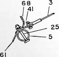
16 Fig. 6a is an enlargement from Fig. 6;
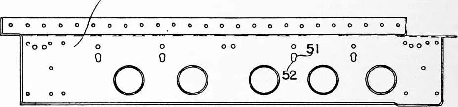
17 Fig. 7 is a side view of the inside of one of the outer deck ring sections;
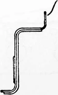
18 Fig. 8 is an end view of Fig. 7 showing how the ends of adjacent sections intemest where they connect together;
19 Fig. 9 is a top view of Fig. 7;
20 Fig. 10 is a detail showing how the tension strands connect with the upper flange of the outer deck ring;
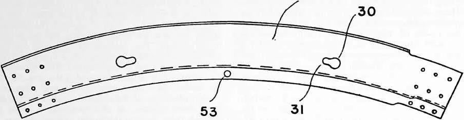
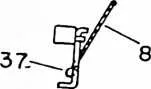
21 Fig. 11 is a side view of the inside of one of the inner deck ring sections;
22 Fig. 12 is a view like Fig. 8 excepting that it applies to the inner deck ring;
23 Fig. 13 is a top view of Fig. 11;
24 Fig. 14 is a sectioned view showing how the flooring beams connect with the deck rings;
25 Fig. 15 is a cross section showing the connection between a flooring beam and the inner deck ring;
26 Fig. 16 is an enlargement taken from Fig. 14;
27 Fig. 17 is a transverse section through the deck showing how it is trussed;
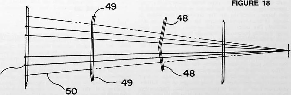
28 Fig. 18 is a plan layout of Fig. 17;
29 Fig. 19 is a side view showing the inter-fastened ends of two truss ring sections;
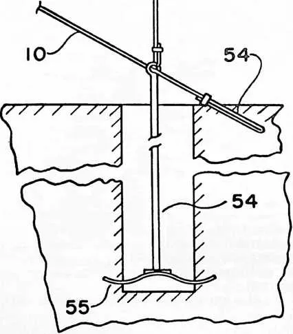
30 Fig. 20 is a detail showing how the outer deck ring is anchored to the ground;
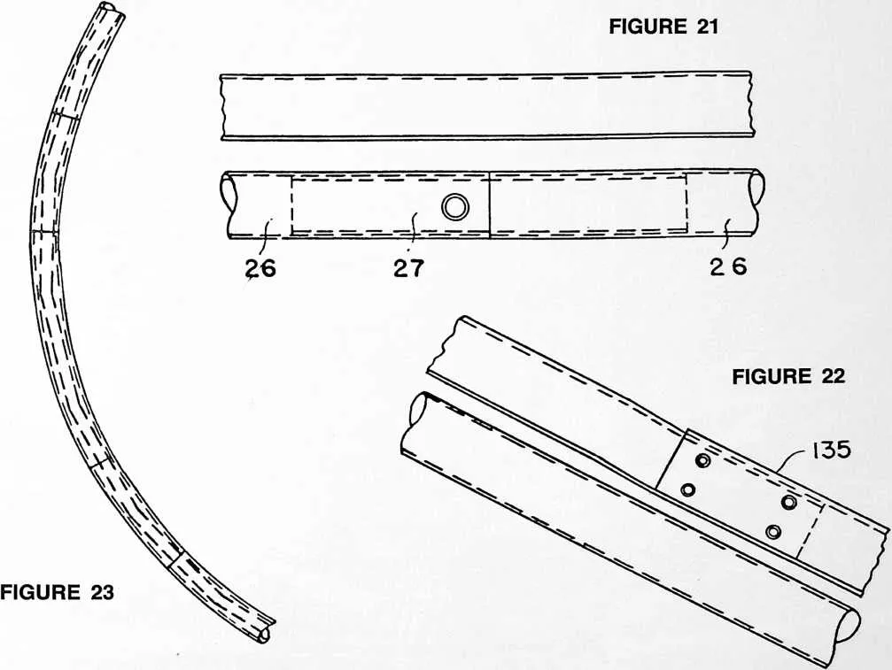
31 Fig. 21 shows how the carling supporting ring is spaced above the upper and inner compression ring;
32 Fig. 22 shows the same as Fig. 21 excepting that it shows the inner joined ends of the carling ring sections;
33 Fig. 23 is a top view of Figs. 21 and 22;
34 Fig. 24 is a cross section showing how the carling supporting ring is fastened to the uppermost compression ring;
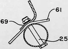
35 Figs. 25 and 26 are cross sections showing how the cowling carling clips are fastened to the intermediate and lowermost compression rings;
36 Fig. 27 is a top view showing how the clips of Fig. 26 appear;
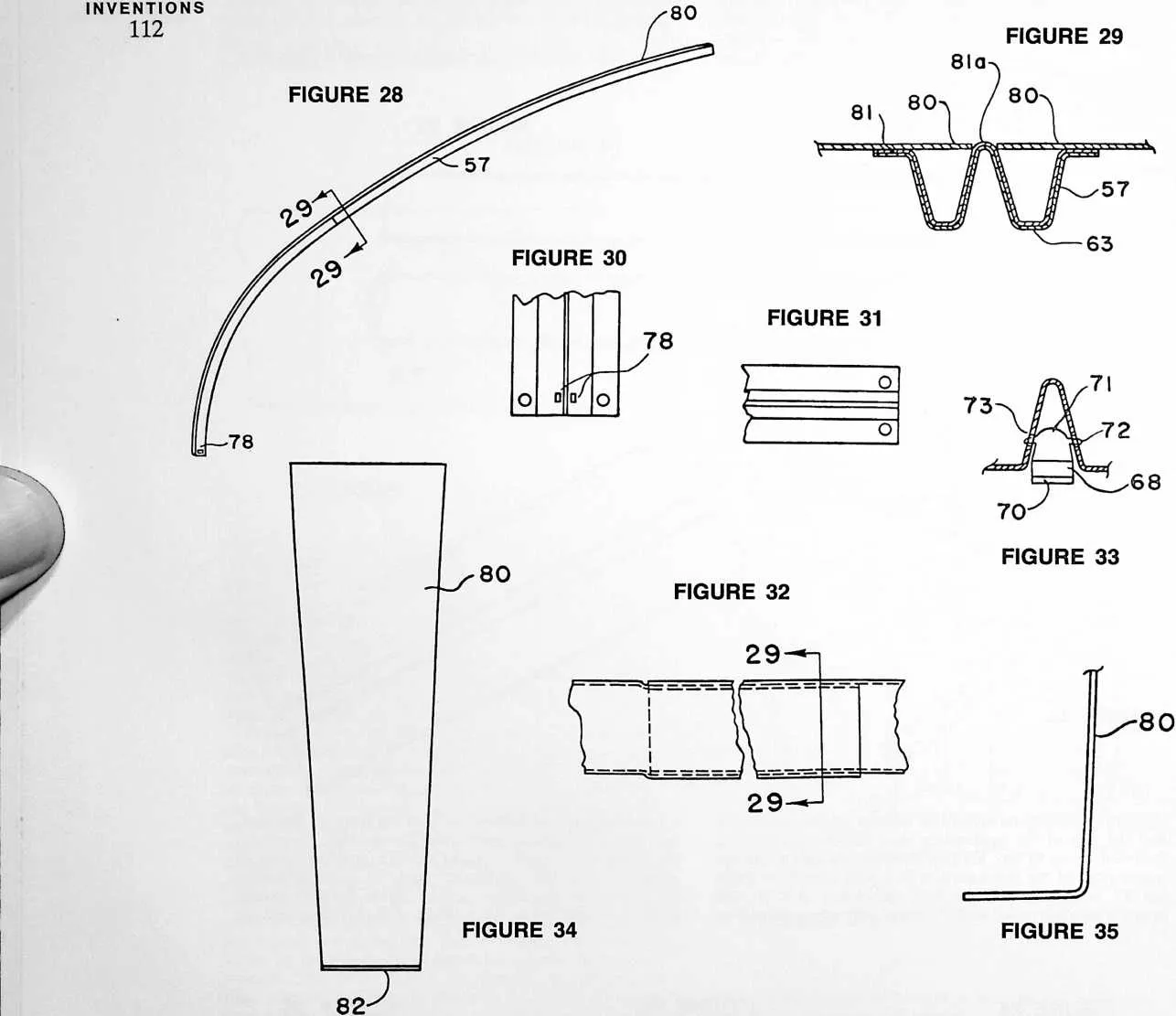
37 Fig. 28 is a side view of one of the cowling carlings;
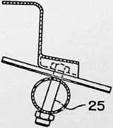
38 Fig. 29 is a cross section taken from the line 29--29 in Fig. 28;
39 Fig. 30 is a top view of the bottom end of a cowling carling;
40 Fig. 31 is a top view of an upper end of a cowling carling;
41 Fig. 32 shows the overlapping joint between two cowling carling sections;
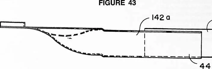
42 Fig. 43 is a side view of the lowermost end of one of the ceiling carlings;
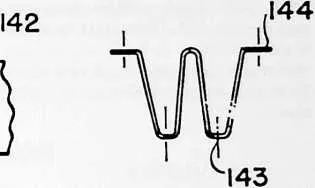
43 Fig. 44 is a cross section taken from the line 44--44 in Fig. 43;
44 Fig. 45 is a top view of Fig. 43;
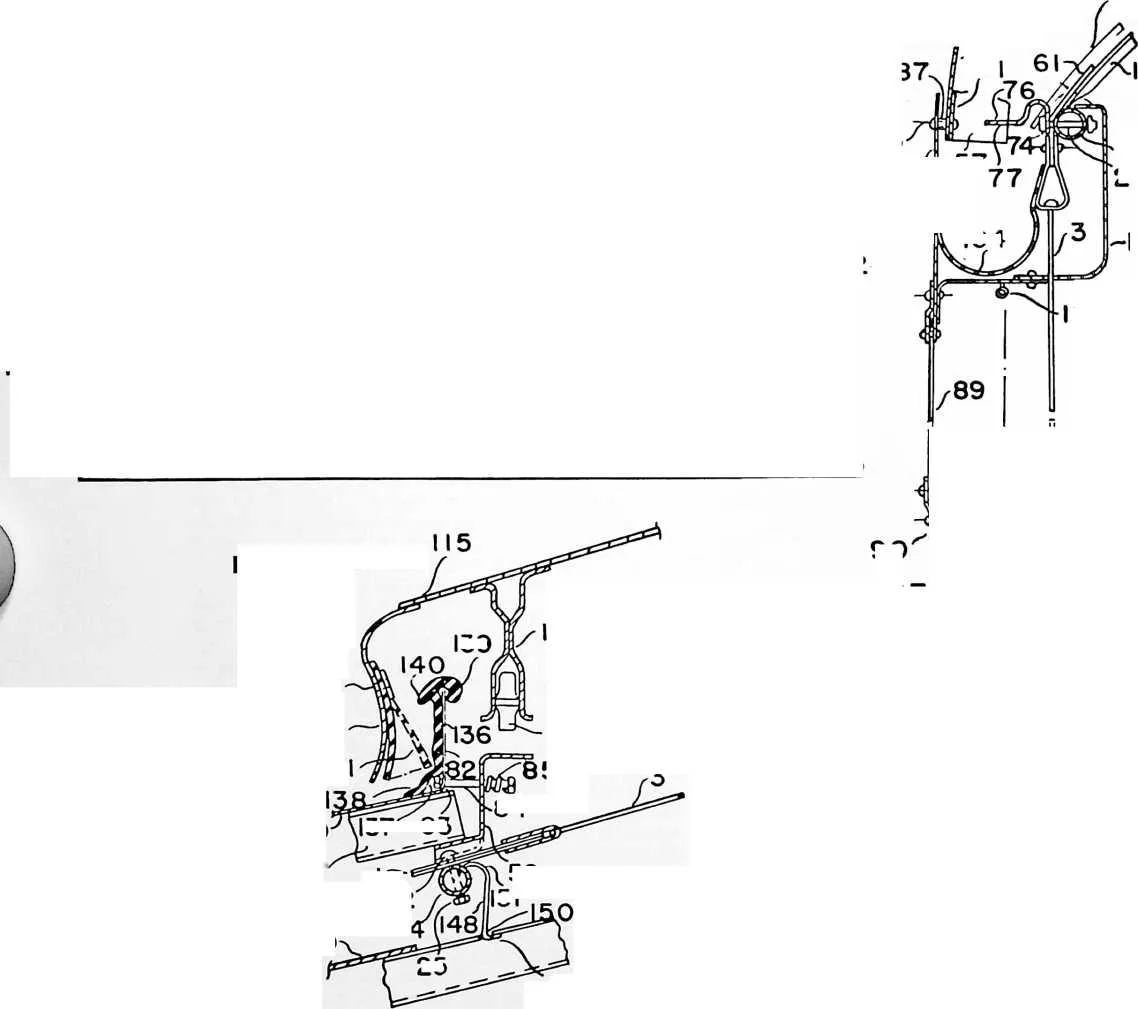
45 Fig. 46 is a cross section showing the various adjacent parts around the uppermost compression ring;
46 Fig. 47 is a cross section through the side portion of the
48 Fig. 33 is a cross section showing how the cowling carling clips work with one of these carlings;
49 Fig. 34 is a top view of one of the cowling gores;
50 Fig. 35 is a top end portion of one of these gores;
51 Fig. 36 is a side view of one of the carling supporting ring sections showing how the cowling carlings connect therewith;
52 Fig. 37 is a top view of Fig. 36;
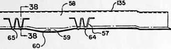
53 Fig. 38 is a cross section taken from the line 38--38 in Fig. 36;
54 Fig. 39 is an edge view of one of the clips for connecting the cowling carling through the intermediate compression ring;
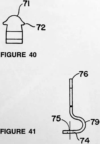
55 Fig. 40 is a side view of Fig. 39;
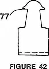
56 Figs. 41 and 42 are similar to Figs. 39 and 40 excepting that the clip is the one connecting the cowling carling with the lowermost compression ring; house around and beneath the uppermost compression ring;
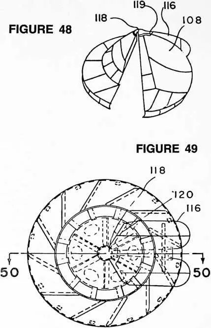
57 Fig. 48 is a broken-away perspective of the rotating ventilator shown on top of the house of Fig. 1;
58 Fig. 49 is a top view of this ventilator;
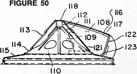
59 Fig. 50 is a cross section taken from the line 50--50 in Fig. 49;
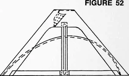
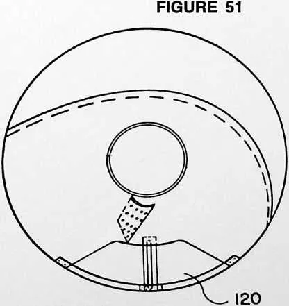
60 Figs. 51 and 52 are top and side views of the ventilator’s outer cone only;
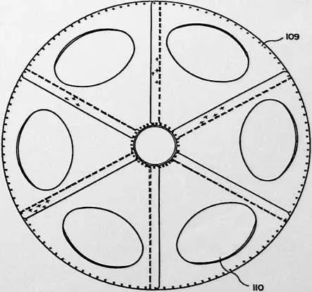
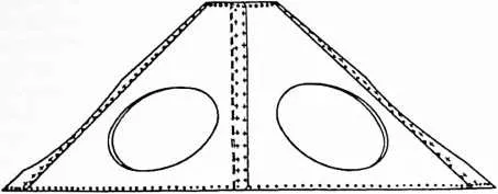
61 Figs. 53 and 54 are top and side views of the ventilator’s inner cone only;
62 Fig. 55 is a cross section through the house generally indicating the association between details shown by the previous figures;
63 Figs. 56 and 57 are cross sections showing details illustrated by previous figures;
64 Fig. 58 is a top view of the gutter used by the house;
65 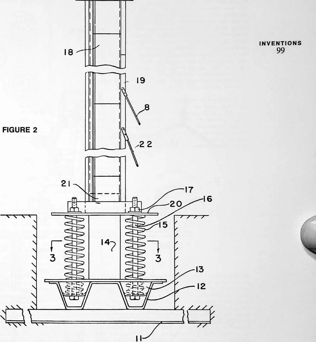 Fig. 59 is a cross section taken from the line 59--59 in Fig. 58;
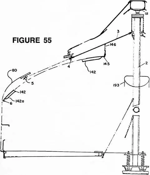
66 Figs. 60 and 61 are top and side views of a window sill section;
67 Fig. 62 is a cross section taken from the line 62--62 in Fig. 60;
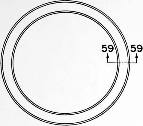
68 Fig. 63 is a top view of one of the flooring panels;
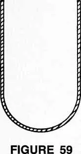
69 Figs. 64 and 65 are sections taken from the lines 64--64 and 65--65 in Fig. 3;
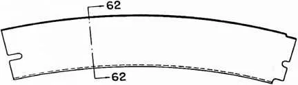
70 Figs. 66 and 67 are side and end views of one of the saddle and dowel units used to connect the flooring beams with the deck rings;
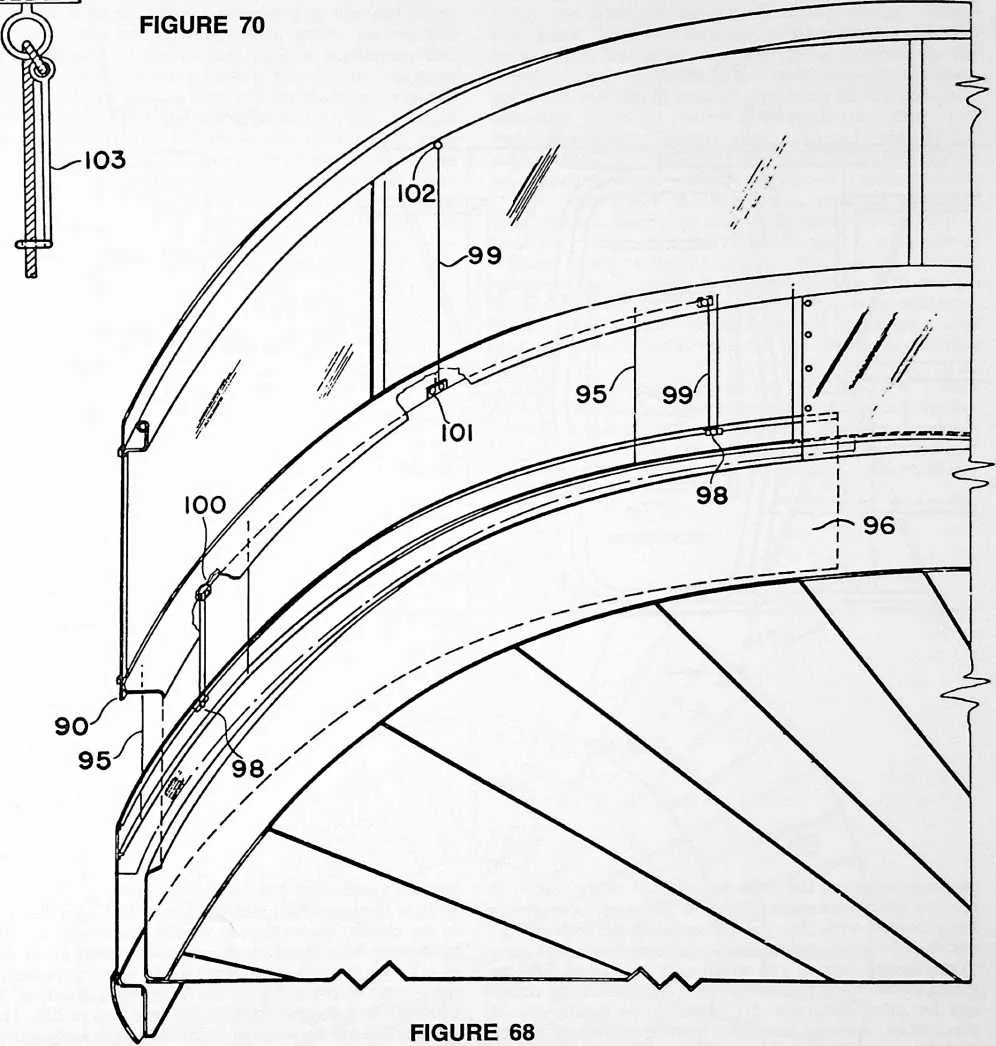
71 Fig. 68 is a perspective looking from the inside of the house toward the outer edge of the deck and the inside of the house side;
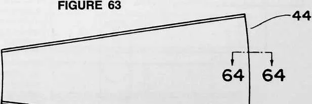
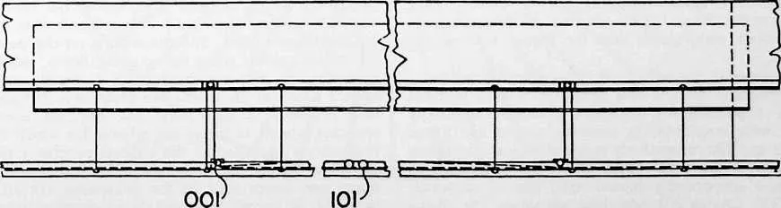
72 Fig. 69 is an elevation of details shown in Fig. 68;
73 Fig. 70 is an enlargement showing a detail in Figs. 68 and 69;
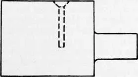
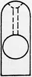
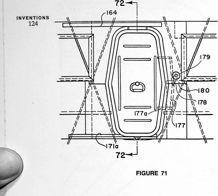
74 Fig. 71 shows the front of the door of the house and adjacent portions of the house side;
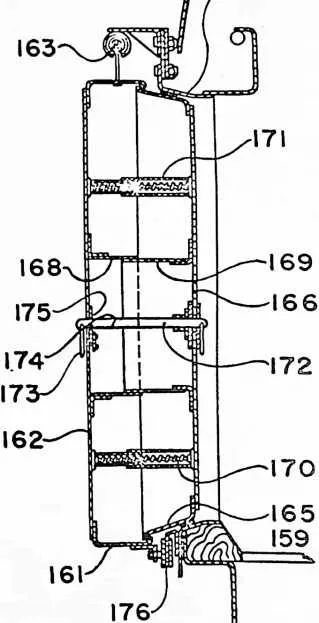
75 Fig. 72 is a cross section taken from the line 72--72 in Fig. 71;
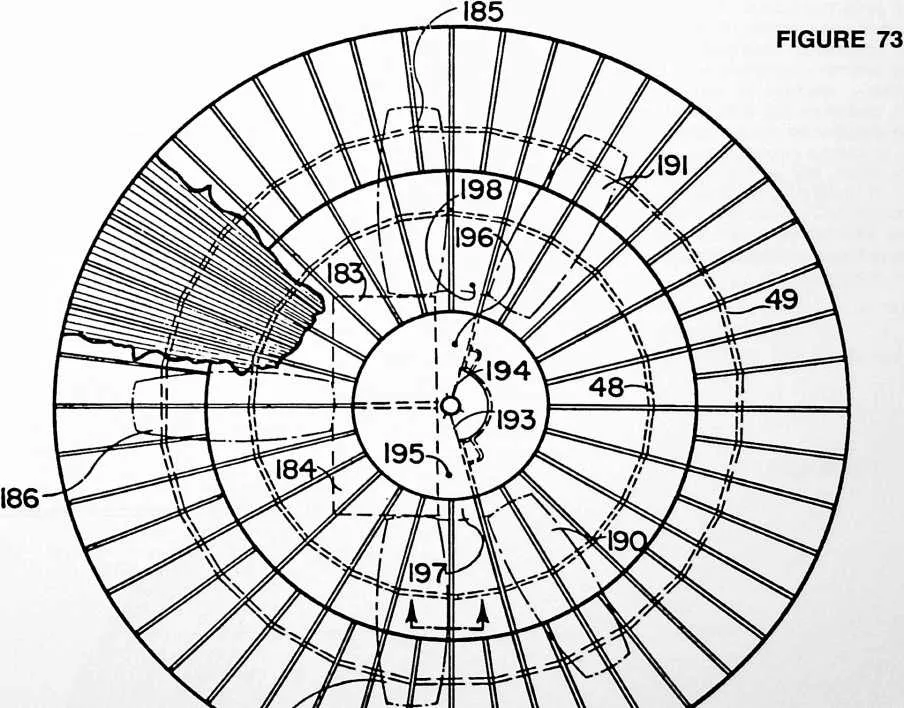
76 Fig. 73 is a partially broken-away plan of the deck; and
77 Fig. 74 is an end elevation of the mechanism operating the endless conveyer system used in at least one of the wall units of the house.
78 This illustrated house includes two bedrooms, two bathrooms, an entrance hall, living room and kitchen, but all of the parts required to assemble this house and its foundation can be manufactured in a factory and grouped into a unit package approximating the size and weight of a crated large automobile of current manufacture. The
79 100
82 FIGURE 3
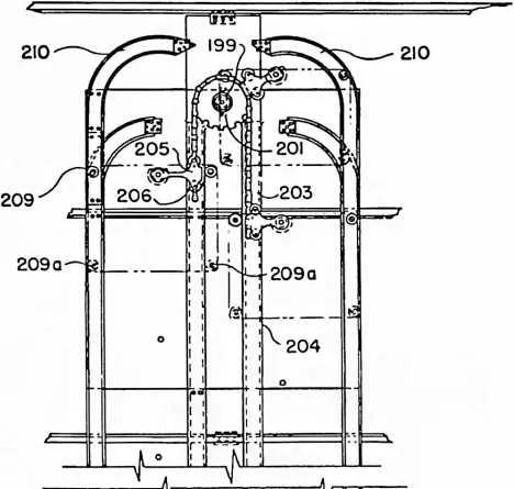
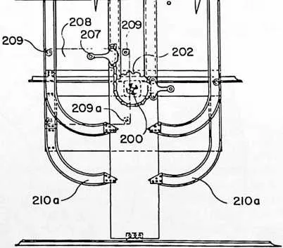
83 extremely stable structure with all the compression stresses carried by the compact compression mast and compression rings and with all the other major parts carrying tension only so that they may be made very thin in cross section and take advantage of the great tensile strengths of presently available metal alloys. The provision of a frame and skin made according to these principles is responsible for the production of a comparatively large house assembled from parts very light in weight and which may be mass produced largely as thin-gauged sheet-metal pressings and drawn shapes, and packaged very compactly. The circular shape contributes to the lightness too, because this shape provides for the maximum enclosed volume with the least amount of materials.
84 The footing 1 provides a broad base in the subsoil, for supporting the compression stress of the mast, and it also functions as a spring for continuously biasing the mast upwardly in an elastic manner, whereby thermal expansion and contraction of the house components may be accommodated by permitting vertical movement of the mast bottom while keeping tension on the tension-carrying parts of the house. Under some circumstances this spring action is unnecessary.
86 18
87 FIGURE 4
88 parts, and therefore the assembled house, are capable of mass production as this term is used in the automobile industry. Each part is adequately light and small to permit its being handled manually by one or two men during the assembly of the house. The assembled house provides for its own foundation, no large excavations being required for this.
89 Since the house may be manufactured by mass production methods, its total manufacturing costs are low by comparison with the total cost of making the components of a conventionally constructed house of comparable size. The cost of shipping the house is radically lower, to a critical degree, than the cost of shipping the components of a comparably sized house of conventional construction, and the house may be assembled in the field by a few skilled mechanics, as contrasted to the large number of laborers and craftsmen required to construct a conventional house of comparable size. Therefore, it is economically practicable to make the parts of this house from the best of the structural metal alloys, such as aluminum alloys and the stainless steels.
90 Broadly speaking, the house is made almost entirely of aluminum alloy and stainless steel and it includes a footing 1 placed in a comparatively small-diametered hole dug in the ground to just safely below the frost level, a compression mast 2 supported by this footing and extending vertically for approximately the height of the house, tension strands 3 spreading outwardly from the upper portion of this compression mast and bearing against compression rings 4, 5 and 6, spreading these tension strands in a shape approximating a dome, and a floor or deck 7 in the form of a flat annulus suspended around its outer periphery by portions of the strands 3 which depend vertically from the outer and lower compression ring 6 and around its inner periphery by strands 8 supported by the compression mast between its upper and lower portions. The outer periphery of the deck is anchored by vertical tension strands 9 and is held against rotation by diagonal stabilizing strands 10, the lower ends of the strands 9 and 10 being anchored to the ground. Stressed sheet-metal skins provide a roof or cowling and a cylindrical side, all supported by the mast working through the tension strands 3.
91 A house constructed as described above provides an
92 The mast footing includes a lower level of channel bars 11 and an upper level of upwardly facing channel bars 12 transverse to the bars 11. These bars may be of the same size throughout but in all events it is preferred that they have shapes permitting compact intemesting when packaged. A spring cluster basket 13 is carried by the upper level of channels 12 with its baskets depending into these channel bars, and a mast guide 14 extends upwardly from this basket to the mast and is constructed or associated with the mast to permit guided vertical movement of the latter. Compression springs 15 extend upwardly from the spring baskets, as a geometrical cluster around the guide 14, and are compressed by tension bolts 16 having nuts 17 above a mast base 20, to be described presently, the bolts projecting through this base and the latter being guided by the mast guide 14.
93 All of the above parts, excepting the mast base, are preferably made of stainless steel, to resist corrosion, and the footing is placed in a hole in the ground, in the manner usual in the case of a tower footing, but preferably without filling the removed dirt back into the hole. The idea is to provide an elastically restrained yielding effect somewhere between the mast beneath its connection with the strands 3 and the ground, although this effect could be introduced into the tensioned strands but with greater difficulty in obtaining geometrical uniformity. This elastically restrained yielding is theoretically necessary to take up thermal expansion and contraction but, due to the novel stress pattern of the house and the opposite thermal effects between the compression and tension members, such yielding may be unnecessary excepting to the extent that it is inherent to the house.
94 The mast 2 is made from a plurality of partially cylindrical sections 18 with their edges having outwardly radiating flanges 19 which are fastened together by fasteners such as rivets or bolts, the various sections together forming a cylindrical mass of great compression strength and stiffness to bending, the inter-fastened flanges contributing greatly to the latter characteristic. Preferably these mast sections are aluminum alloy extrusions. For greater convenience in packaging, these mast sections are made against falling down around the mast by a series of steps 24 fixed to the outwardly radiating flanges of the mast sections 19. The tension strands 3 may be wire ropes but solid constructions are preferred, such as solid rods. When rods are used, the connections between the tension strands 3 and the ring member 23 may be by way of pin and clevis connections.
95 From the upper part of the mast, the tension strands 3 extend outwardly and downwardly over the various compression rings 4, 5, and 6 and from the ring 6 vertically downwardly, and these strands are graduated in cross-sectional areas and arranged geometrically, as crisscrossing diagonals, as required to carry the maximum tension
96 FIGURE 6
97 shorter than the total length of the mast, some being longer than others so that the flanges of the longer upper ones may be fastened to the flanges of the shorter lower ones and vice versa, whereby to effect a strong joint. The individual sections are light enough to be manually handled by one or two men and their shape permits them to be intemested for compact packaging. and torque stresses with the least amount of materials. The tension strands are of the larger cross-sectional areas when they first leave the mast and gradually reduce in these dimensions as they progress outwardly and downwardly, this being because the tension stress on them decreases to the extent that the weight carried by these strands decreases and because their number is geo-
98 FIGURE 6a

100 The mast is centered respecting the mast base by a centering plate 20, this centering plate being an aluminum alloy casting and having a centering stud 21 fitting inside the mast. Tension strands 22 are fastened to the mast partway up its height and extend down to anchorages embedded in the earth at spaced locations around the footing. These strands function as guys which steady the mast immediately after its erection and prior to further assembly of the house, and they also provide greater rigidity in the case of the completed assembly.
101 The tension strands 3 are fixed to the mast near its top by a ring member 23 which encircles the mast and is held metrically doubled at the ring 4. Where the strands pass over the various compression rings they may be fixed against relative slipping by fastenings 25, which also hold the rings against the strands, and the various lengths of strands, required to effect most conveniently the reductions in the cross sections of the strands outwardly and downwardly, are inter-fastened in any adequate strong manner that is flexible or pivotal, so that the strands may be folded for packaging or capable of easy field assembly. These strands and their connections are preferably made of high tensile strength stainless steel.
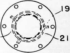
102 The various compression rings 4, 5 and 6 are each
103 made from a plurality of extruded aluminum alloy tubular sections 26 of convenient lengths for packaging, the various sections being joined together in the field around the mast, during the erection of the house, by means of dowels 27 retained in one end of each section by fastenings to restrain them from slipping longitudinally, into any one ring tube, which would permit the joint to come apart. These various rings are not truly circular but are made up of straight sections extending transversely between the points of their connections with the various tension strands, this being because a straight section is better able to carry compression than is a curved section. That is to say, the compression rings are made up of a plurality of straight sections between the various points of connections with the various tension strands, there being enough of these points for the rings to closely approximate the circular contour of the outer periphery of the deck below. These various rings may be made with dif-
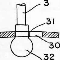
104 two men and are Z-sections so that they may be nested compactly together for packaging. Their upper flanges are provided with holes 30 from which narrow slots 31 extend, the lower ends of the strands 3 being provided with enlargements 32 on their ends which will pass through the holes 30 but not through the slots 31, whereby the enlargements may be dropped through the holes 30, during the assembly of the house, and moved over into the slots 31 so as to transmit the tension stress on the strand to the outer deck ring, and the deck weight to the strands. The slots should extend in the diagonal directions of the various strands so as to assure a constant tendency to pull the enlargements 32 away from the holes 30 and under the metal surrounding the slots 31. Each of the sections 29 is provided with fastening holes arranged so that when one of the Z-section ends overlaps another these holes register, so that fastenings may be passed through them to inter-fasten the various sections. Also,
105 FIGURE 7
107 92
109 FIGURE 8
110 ferent cross-sectional areas as required by the different compression stresses they must carry.
111 The vertical portions of the strands 3, which depend from the ring 6 so as to support the outer periphery of the deck 7, are fastened to an outer deck ring 28 which is made of a plurality of partially circular Z-sections 29 stamped or extruded from aluminum alloy and arranged so that when inter-fastened with their webs vertical they provide the circular contour needed. These sections are made in appropriate lengths for easy handling by one or the webs of the various sections are preferably provided with lightening holes.
112 It might be mentioned at this point that wherever possible the parts of the house are constructed in the manner of aircraft parts so as to obtain great lightness in the case of the completed structure without any loss of adequate structural strength. Also, they are made to intemest, during packaging, in all practicable instances.
113 The deck includes an inner deck ring 33 which is also made of stamped or extruded aluminum alloy in the form of sections substantially similar to those of the outer deck ring, excepting for curvature, the inner deck ring being much smaller in diameter than the outer and encircling the mast fairly closely. Thus, the various sections 34 of the inner deck ring are also partially circular Z-sections, which may be assembled with their ends overlapping and fastened together by way of suitable fastening holes which may be registered appropriately, but there is one difference in that the tension strands 8, from which the inner deck ring hangs from the mast, are formed in the webs of the inner deck ring sections, the holes being shown at 35 with their slots at 36, the slots 36 extending vertically so that the enlargements 37, on the end of the tension strands 8, will be drawn upwardly and away from the holes 35 and snugly into the slots 36.
114 The deck beams radiate from the inner deck ring to the outer deck ring and are in the form of W-sections 38 which are narrowest at the inner deck ring and gradually
115 104
116 FIGURE 10
117 FIGURE 11
118 FIGURE 12
120 INVENTIONS
121 105
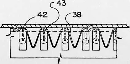
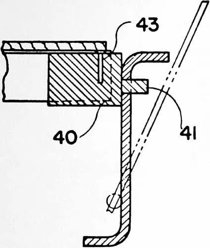
122 flare, with the increasing diameter, as required to make a deck structure, in the form of an annulus, the W-sections being arranged transversely horizontal and having depending flanges 39 on their longitudinally extending side edges. Connection between the W-sections and the inner and outer deck rings is effected by cast aluminum alloy units including saddles 40 having dowels 41 which fit properly positioned holes in the webs of the inner and outer deck rings, the W-sections 38 having their upwardly looped portions resting on the saddles 40, and top edge flanges 42 also resting on such saddles, and connected therewith by fastenings 43 during the assembly of the deck in the field.
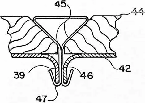
123 The flooring for the deck comprises radial flooring panels 44 that radiate from the inner to the outer deck rings and which also appropriately flare to provide a complete flooring, the edges of the panels 44 being downwardly beveled and being fastened to the deck beams by clip bars stamped from aluminum alloy to provide a triangular cross-section 45 and depending flanges 46 which terminate with upwardly extending clip edges 47 that clip beneath the flanges 39 of the W-section floor beams, whereby to fasten the latter laterally together with the triangular cross section portions keying the flooring panels 44 in place. The clip bars may be placed in position prior to the flooring panels 44, during the assembly of the deck, the tops of the W-sections being substantially flush with the tops of the upper flanges of the outer deck Z-sections, whereby the flooring panels may be slightly spaced outwardly, laid down so as to clear the triangular section 45 of the clip bars, and then shoved slightly inwardly so as to key beneath these triangular sections. The flooring panels are preferably made of either wood or plastic, for aesthetic reasons, and they may be made in sections of less length than the full length required by the use of a single inner panel having an outer end edge against which two other panel sections abut and from which they continue to radiate, this requiring long and short clip bars, all as illustrated.
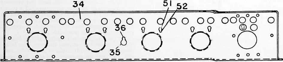
124 To assure adequate deck stiffness with least weight, the W-sections 38 gradually become deeper from the inner deck ring toward the outer deck ring, their ends at the latter location being deepest. Furthermore, a plurality of truss rings 48 and 49, which may each be made of aluminum alloy Z-sections constructed and arranged along the lines described in connection with the inner and outer deck rings, are arranged concentrically beneath the deck beams so as to bear against their bottoms, and tension strands 50 are fastened to the webs of the inner and outer deck rings so as to radiate therebetween and alternately bear against the bottoms of the alternate truss rings, these strands being highly tensioned so that the deck becomes a stressed truss assembly of great rigidity. The inner and outer deck rings are provided with more of the holes 51 and slots 52, in their webs, so that by providing enlargements 53 on the ends of the strands 50, the strands may be fastened to the deck ring webs. The strands 50, forming the truss sling, may pass through the truss rings via slots 54 formed in these rings where required for this purpose, and the truss rings may advantageously be a plurality of straight sections, rather than partially circular sections as are the deck rings, with all
125 FIGURE 13

128 FIGURE 14
129 the parts arranged as required to obtain the maximum structural stability. These truss sling tension strands pull the inner and outer deck rings in the direction of each other while these rings are simultaneously strutted apart by the W-section floor beams, this action forcing the dowels 41 and the adjacent portions of the saddle 40, fixed to the inner and outer ends of the deck beams, in the directions of the rings so that the entire assembly is rigid and free from rattles.
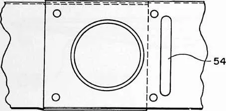
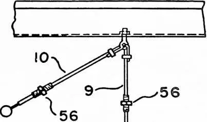
130 The bottom flange of the Z-section outer deck ring 29 extends radially inwardly and is provided with holes for receiving fastenings for the anchoring strands 9 and the diagonal stabilizing strands 10. These strands are firmly fastened to the ground by tension rods 54 that extend downwardly through small-diametered holes dug well down into the ground, as by means of a posthole digger, with their bottom ends anchored by means of anchors 55 such as are used for ground anchorage purposes gener-
134 108
135 FIGURE 15
136 FIGURE 16
137 ally, the holes being filled over these anchors in the usual manner. Preferably, the various anchors and stabilizing strands are provided with turnbuckles 56 for the purpose of leveling the deck, and the house generally, when the ground is uneven.
138 With the house framework erected as described, the roof may now be assembled. This roof, in part, is in the form of a dome adapted to function aerodynamically somewhat like the cowling on an airplane, so it is called a cowling.
139 The cowling assembly includes a plurality of W-sections 57, permitting intemesting for packaging, that radiate from the ring 4 down over the top of the ring 5 and to the ring 6, these three rings supporting the weight of the cowl. These W-sections constitute radial carlings which are circumferentially spaced sufficiently closely to provide the strength required to resist all the stresses to which the cowling will be subjected. Each carling or W-section is made up of a plurality of lengths with the upper lengths overlapping the lower or outer lengths to provide a joint which is completed by watertight fastenings.
140 A carling supporting ring is formed by partially circular pieces of Z-sections 58, which permit internesting, assembled to form a circle above the ring 4 with their bottom flanges extending outwardly, these flanges being formed to angle downwardly from the horizontal. All or a number of the Z-sections have these lower flanges pressed downwardly below the level of their remainders, as at 59, and these portions 59 have holes 60 to provide for their fastening to the ring 4 by means of the same fastenings fixing the tension strands 3 to this ring. As explained before, the various strands 3 are made with different cross-sectional areas, this requiring their joining, and this is done by flat straps 61 which lie on top of the various rings and have holes 62 which register with the holes 60 in the carling supporting ring sections so that the fastenings 25 may be in the form of bolts or rivets fastening all these parts together. Since the straps 61 are under heavy tension they remain flat at all times and provide firm support for the flange portions 59, thus holding the carling supporting ring firmly in place with the webs of its various sections 58 vertical.
141 The W-sections 57, forming the carlings, have the bottoms of their depending loops formed as flanges 63 and these flanges rest on the outwardly extending flanges of the Z-sections 58 of the carling supporting ring and are fastened there by rivets or bolts 64 passed through the flanges 63 and the flanges of the sections 58 by way of registering holes 65, in the ring flanges, and 67, in the carling flanges. The arrangement is such that the carlings are fastened to the carling flanges away from the latter’s depressed portions 59 so that the upper ends of the carlings are spaced above the ring 4 and terminate thereover.
142 Upstanding clips 68 are applied to ring 5 by the fastenings 25, the arrangement being generally similar in this respect as at the ring 4, each clip having a curved flange 69 fitting the curvature of the strap 61, where it passes over the compression ring 5, and which is provided with a hole 70 for receiving the fastening 25. The upstanding portion of the clip is provided with a smoothly rounded head 71, which flares downwardly to lips 72, and the various W-sections, from which the carlings are made, are provided with holes 73 in the side walls of their middle loops so that by pushing a W-section downwardly, over the head 71, its middle loop sides spring outwardly, due to the camming action of the head 71, until the lips 72 of the clip register with the holes 73, whereupon the middle loop sides spring together again and the carling is held firmly by the clip. This requires that the clips be arranged transversely respecting the carlings. The clips should be sufficiently high so that the holes 73 may be formed well above the flanges 63 of the W-sections, forming the cowling carlings, so that water running down the flanges 63 of the W-sections will not leak through these holes.
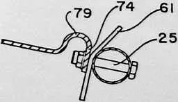
143 The lower ends of the cowling carlings terminate at about the level of and outside of the compression ring 6 and at those locations their ends are connected with the ring 4 by clips somewhat similar to those already described, these clips each having a base 74 provided with a hole 75 through which the fastening 25 passes, which fixes the strap 61, interconnecting the tension strand lengths at the ring and which lies outside the ring, to the ring. Since the carlings are curved, so that together they provide a dome contour, their lowermost ends approach the vertical, so the clips at the ring 6 each have a horizontal ex
144 tending portion provided with a head 76 and lips 77 for fitting the holes 78 formed as previously described in the cowling carling W-sections. Furthermore, these clips, for the fastening 25, are each provided with a gooseneck 79 so that the carlings are free to move longitudinally without causing trouble, the elasticity of the clips at the ring 5 also permitting such motion. This permits accommodation for thermal expansion and contraction and for strain resulting from stress.
145 The cowling, covering the domed framework provided by the carlings, is made up of a plurality of gores 80 made of sheet aluminum alloy with each gore free from joints its outside and is engaged in each instance by one of a series of tension screws 84 which extend horizontally through the upstanding wall sections and the webs of the Z-sections 58, forming the carling supporting ring, these screws 84 being provided with compression springs 85 so that there is a continuously exerted and upwardly directed elastic tension placed on all the cowling gores. At their lower ends, these gores are rigidly fastened to the flanges 81 at the lower ends of the cowling carlings 57. Therefore, the cowling gores 80 are continuously tensioned upwardly so that they fit tautly over the carlings provided for their support. Any leakage that might occur
146 FIGURE 17

148 so that by arranging them radially on top of the cowling carlings with the edges of the various gores positioned so that they abut, in each instance, the outside of the upwardly extending loop 81A of the W-sections forming the carling underneath. This arrangement positively positions the gores and prevents their rotation when they are tensioned, as well as providing a tight joint, the gore edges wedging between the loops 81A. The upstanding edges of the outer legs of these W-sections are provided with longitudinal flanges 81 which provide good bearings for the cowling gores 80. There is a cowling gore filling the space between each two of these carlings. Each gore flares from its top to its bottom, as required by the increase in diameter of the domed shape, and each gore is bent upwardly at its inner end to provide a vertical wall section 82, these upstanding wall sections of all the gores providing a cylindrical wall structure at the tops of the carlings at their upper ends.
149 A nut 83 is provided for each upturned gore end 82 on between the radiating longitudinal edges of the gores and the carlings is caught in the troughs provided by the W-section carlings underneath, the water running down in the carlings and dropping from their lower and outer ends.
150 This rigid fastening of the bottom ends of the gores to the bottom ends of the carlings is effected by fastenings 86 such as rivets, and these extend outwardly through spacers 87 and fasten a cylindrical depending skirt 88 of sheet aluminum alloy around the periphery of the house, this being made of sheet segments so they may be packaged and handled conveniently. This depending skirt 88 comprises a tension member from which the cylindrical siding of the house depends with the weight transmitted through the carlings upwardly to the various compression rings in a distributed manner. This siding, in part, comprises a cylindrical wall 89 of transparent plastic material riveted or otherwise rigidly fastened to the lower edge of the skirt 88. Excepting for the door or doors, this trans-
151 53
153 parent strip or wall section extends completely around the side periphery of the house. There are limitations on the available length of such material as it is now made but by using sections with overlapping ends which are rigidly fastened together, by rivets or the like, it may be made as a continuous piece. This strip of transparent plastic hangs in tension from the skirt 88, its lower edge terminating at about the height customary for windows in homes. This lower edge rigidly carries a short cylindrical skirt 90 and a circular window ledge 91 made up of as-
154 The above-described construction leaves a cylindrical opening completely around the house, and this is closed by partly cylindrical sheet aluminum alloy sections 96 with each section depending from its own piece of partly circular angle bar 97 having apertures through which the tension rods 95 pass, the bottom edges of these partly cylindrical sections 96 lying outside of the upstanding skirt 93 and the angle bars 97 riding the tension rods 95 so that the latter function as vertical guides. There are enough of the tension rods 95, distributed around the pe-
155 FIGURE 19
157 sembled partly circular Z-sections with their webs horizontal, their outer flanges being upstanding and fastened rigidly to the lower window edge and their inner flanges depending. This window ledge also encircles the house beneath the window, with the strands 3 extending down through it and aiding in its support by having enlargements 91A secured to them beneath the windowsill, and is made of overlapped sections having lengths compatible with compact packaging and easy handling. In these parts again, aluminum alloy is used.
158 Going now to the bottom of the side, the outer deck ring 29 is made of partly circular Z-sections, as will be remembered, and the outwardly extending upper flanges of these sections are turned upwardly to provide a vertical flange 92 and a skirt 93, made of partly cylindrical sheet aluminum alloy sections that are inter-fastened, extends upwardly from this flange 92, this upstanding skirt being rigidly fastened to this flange. This skirt does not reach to the bottom of the windowsill 91 but terminates well below it, its upper edge being rigidly fixed to the vertical leg of an angle bar section ring 94 that encircles the house, excepting for the doorways, and which is made of inter-fastened lengths for reasons already described. The other leg of the section, comprising this ring, extends horizontally inwardly from the upstanding skirt 93 and interconnects near its outer periphery with the web of the windowsill 91 by way of tension bars 95 which draw the depending skirt 88 and the transparent plastic sheet window wall 89 downwardly, while drawing the angle ring 94, and therefore the skirt 93, upwardly.
159 The windowsill 91 and the parts above it depend from the carlings and cowling as previously described, so they naturally are tensioned and hang straight so that flexible materials may be used in their construction. The tension rods 95 transmit the weight of the skirt 93 to the windowsill and therefore upwardly to the other parts.
161 FIGURE 20
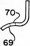
162 riphery of the house, to provide at least two of these rods for each of the partly cylindrical sections 96 so that the latter are adequately steadied when raised or lowered. This is one of the ways in which ventilation is provided, the angle bars 97 in each instance being provided with sheaves 98, near each of its ends, and cables 99 being arranged for each of the sheaves 98 so that each cable is fastened to the bottom of the windowsill 91, extends vertically downwardly and around a sheave 98, upwardly to a sheave 100, also fixed to the windowsill bottom and horizontally beneath the windowsill bottom, the cables from either end of each section approaching each other, to a sheave 101 at about the center of each section and fixed to the windowsill bottom, the cables 99 then being fastened together and one of them going vertically upwardly, through a hole in the windowsill, to a sheave or ring 102, fixed well above the windowsill, through which it bends and starts downwardly, its end then being provided with a guide 103 which guides this end along itself in a parallel fashion downwardly. With this arrangement, when ventilation is not desired the guide 103 is pulled downwardly so as to lift the section 96 upwardly and along the vertical edges of these sections 96 so that these strips cooperate with the edges of the sections to form tongue-in-groove sliding joints. Since the cylindrical sections 96 depend from the angle bars 97, they may be made of flexible sheet metal without causing difficulties in the way of their bending. When the sections 96 are raised their lower ends should overlap the outside of the upstanding skirt 93 sufficiently to provide a watertight effect.
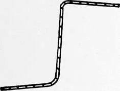
163 It will be remembered that the depending skirt 88 is
165 close the opening between the bottom of the windowsill and the top of the upstanding skirt 93, the guide being fastened down in any manner desired. By extending the upper edge of the sheet section 96 a little above the angle bar 97, it fits beneath the little depending skirt 90 and forms a weatherproof seal. Vertical strips may be placed spaced from the outside of the cowling forming the roof, and that leaking water runs down the carlings. Therefore, the house is provided around its entire periphery with an annular gutter 104, preferably made of material having the properties of synthetic rubber, inside the skirt 88 and in line and just below the outside of the cowling and the
166 FIGURE 24
167 FIGURE 25
168 FIGURE 26
170 FIGURE 27
172 carling lower ends. This gutter may be semi-circular in cross section with one upstanding wall fixed watertightly to the inside of the depending skirt 88 and with its other upstanding wall fastened so as to keep the upper edges from spreading, this being illustrated as being done by fastening the inner wall of the gutter 104 to the connections for the tension rods 3 just below where their straps 61 pass over the ring 6. To assure permanent watertightness, the ring 6 is preferably an extruded synthetic rubber section having its ends permanently vulcanized together. This gutter 104 is completely enclosed and invisible from the outside of the house. In addition to catching rainwater, it performs the further very useful function of catching condensate which might form on and run down the inside of the cowling or the carlings.
173 Preferably, a header 105, made of pressed sheet aluminum alloy as partly circular sections, is installed above the window so as to completely enclose the gutter 104,
175 114
176 FIGURE 36
177 the connections for the tension rods 3 and the compression ring 6, this header being provided for aesthetic reasons. Its various sections should be capable of in- temesting.
178 The domed cowling goes upwardly and inwardly only to the compression ring 4, this leaving a large-diametered hole surrounding the mast. This hole is closed by a large rotating ventilator 107 having a wind vane 108, the trailing edge of this vane being open and communicating with
179 FIGURE 37
180 FIGURE 38
181 FIGURE 39
182 the interior of the house. The ventilator is designed to cooperate with the domed cowling according to aerodynamic principles, the wind flowing around the cylindrical house smoothly and that portion that flows around the domed cowling being deflected upwardly and circumferentially, the vane rotating the ventilator so that the trailing edge of the vane is always on the lee side of the ventilator where there is a natural reduction in the atmospheric pressure, whereby air -may be continually sucked out from the house so as to obtain forced ventilation inside the house without the need for mechanical contrivances.
183 The rotating ventilator 107 is made of aluminum alloy and comprises an inner cone 109, made of sheet sections that are fastened together, provided around its side with large symmetrically arranged air passage holes 110. The top of this inner cone is open and peripherally connects with an inwardly extending flange 111 and also with a short upwardly extending sheet cylinder 112. The periphery of this cylinder 112 connects with an outer cone 113 which extends downwardly to the bottom periphery of the inner cone 109. Both inner and outer cones 109 and 113 connect at their bottom peripheries with an outwardly curving flared ring 114, the bottom periphery of which connects with a flat conical skirt 115 which extends outwardly so as to overlap the edge of the opening in the domed cowling.
184 The vane 108 is made from sheet side walls which extend away from the outer cone 113 toward the periphery of the lower edge of the conical skirt 115, these sides being close together at their tops, where they are closed by a flat metal plate 116 by joints including angle bars 117 extending along the upper edges of the vane. These sheet-metal side walls flare circumferentially of the ventilator downwardly, the lower edges of the side sheets being joined with the outer conical parts 113 and 115, and with the flaring ring section 114. A circular plate 118 closes the top of the cylinder 112 and has a tail 119 which joins with the plate 116 closing the top of the vane. The trailing or end edges of the side sheets, forming the vane
186 118, are curved away from the wind flow in accordance with good aerodynamic principles.
187 An opening 120 is formed in the outer conical skin 113 inside of the vane so that air can be sucked through the holes 110 in the inner cone, upwardly through this opening 120 and outwardly through the open end of the vane 118. A strengthening bar 121 extends across this opening 120 longitudinally of the outer cone to replace the strength lost by reason of this opening 120; and the side the light weight of the ventilator it may be necessary to bias the plate 127 downwardly by weight or springs so that the ventilator will not rise too easily in the case of minor pressure variations. Due to the aerodynamic construction of the ventilator a high wind will not lift it, but will instead tend to urge it downwardly. However, sudden pressure variations will tend to lift it, so the ventilator should be biased downwardly to an adjusted degree in the manner common to safety valves in general.
188 FIGURE 44
191 sheets of the vane 118 connect with vertical angle bars 122 which, in turn, connect with the longitudinally extending angle bars 117, and an angle bar 123 extends diagonally between the angle bars 122, all to provide further bracing.
192 It is to be understood that this ventilator is made of separate sheets of metal and may be assembled in the field at the site of the house, this assuring compact packaging. Furthermore, all the parts follow aircraft construction, whereby the total weight of the ventilator may be kept very low although, by reason of its construction, its strength is very great.
193 The mast 2 rises to an elevation high enough above the ring 4 to support the ventilator by way of the inwardly extending flange 111 previously described. This flange is rigidly fastened to a hub 124 provided with anti-friction thrust bearings 125 arranged to take thrust both upwardly and downwardly and which are carried by a vertical shaft 126 rigidly fastened to a horizontal plate 127 spaced just above a flange 20A, on top of the mast, and supported against downward movement thereby through the medium of tripod adjusting screws 128. The flange 20A is fixed to the mast top and centered there by a centering stud 21A. These tripod adjusting screws are adjusted so that the ventilator may freely rotate without its outer edges, which overlap the inner periphery of the cowling, contacting the latter. The flange or plate 20A has a hole
- 129.
- formed in its center through which a tube 130 depends vertically from the plate 127, the lower end of this tube being fixed to a disc 131 that rides inside the mast 2 and renders the plate 127 rigid to tilting action. This tube
- 130.
- slides in the hole 129 and the disc 131 slides inside the mast, the idea being that should there be a sudden reduction in pressure on the outside of the house, such as might occur during a hurricane, the entire ventilator may lift up until the disc 131 engages beneath the centering stud 21A depending from the plate 20, the parts 20 and 21 being fastened to the mast. This permits almost immediate pressure equalization between the inside and outside of the house so as to avoid the destruction that would occur in the case of a conventional house. Due to
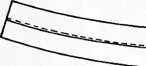
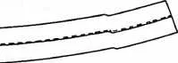
194 The outer periphery of the lowermost and most widely flaring conical skirt 115 carries a depending skirt 132 made of sheet sections rigidly fastened to the periphery of the skirt 115. This skirt depends outside of the wall formed by the upstanding wall sections 82 of the cowling gores 80, is radially spaced from the same and is made of sections which, when assembled, provide a skirt that is vertically concave-convex, this skirt being outwardly concave. The lower end of this skirt is fairly close to the cowling and is well below the upper edge of the wall formed by the wall sections 82 of the cowling gores, but its lower edge is spaced sufficiently above the cowling to clear it in the event of slight tipping action of the ventilator due to strain resulting from wind stresses. The ventilator tipping action is kept within limits preventing intercontact between the cowling and the lower edge of the skirt 132 by means of an annular series of rollers 133 mounted by strutting brackets 134 fixed to the bottom of the conical skirt 115. These rollers 133 contact the upward and inwardly extending flanges of the ring sections 58, forming the carling supporting ring, so that the ventilator can freely turn even should it tip somewhat while its tipping action is rigidly limited. The various ring sections 58 each have one end vertically depressed, as at 135, so that the overlapping end of the next section has its flange upwardly flush with the flange of the first one, whereby the annular surface provided by the tops of the upper flanges of the ring sections 58 provide a smooth trackway for the rollers 133. Due to the conical shape of the ventilator skirt 115, it is inherently rigid to bending even though made of thin-gauged sheets.
195 Since the cylindrical wall, provided by the upstanding end sections 82 of the cowling gores 80, is not circumferentially continuous, water blown against it by the wind through the space between the lower edge of the skirt 133 and the cowling might get inside the house. Therefore, a cylindrical ring 136, made in the form of an extruded section of elastic material having the properties of rubber, is provided. This ring 138 is elastically forced down over the wall formed by the upstanding end sections 82 and provides a watertight barrier. This ring 136 has an outwardly
196 and downwardly flaring flange 137, on its lower edge, which clears the outer ends of the tension bolts or screws
197 84 and which terminates with a foot ring 138 which presses downwardly tightly against the upper surfaces of the cowling gores 80. Its upper edge has an inwardly, downwardly and reversing, looping portion 139, the edge wh’ch grips the inside of the wall formed by the cowl- -| -t r ing gore sections 82, and it also includes an outwardly and downwardly extending flange 140 which positively reverses the flow of water blown upwardly along the outside of the ring 136. Weather tightness is further assured by a cylindrical skirt 141 made of flexible material like rubber and fixed by fastenings 142 to the ventilator skirt 132 above its lower edge, the lower edge of this flexible skirt 141 hanging well below the lower edge of the sheet metal skirt 132. This skirt is flexible enough so that the wind can blow it back against the ring 136 beneath its outwardly and downwardly extending flange 140, so it functions as an air seal on the windward side of the ventilator.
198 152
199 80
200 81
201 142 a
202 86
203 104
204 105
205 102
206 90
207 95
208 96
209 158
210 155
211 153
212 133
213 137--83
214 80
215 182
216 57
217 182 a
218 80
219 25
220 149
221 29
222 58--151
223 134
224 139
225 FIGURE 46
226 142
227 132
228 141
229 61--62
230 57
231 6
232 25
253 94
254 156
255 157
256 84
257 93
258 92
259 Provision for a double roof is made by having ceiling carlings 142 in the form of W-sections which gradually fade into flat sections at each end 142A, the bottoms of the two downwardly depending loops having flanges 143 and the upper edges of the outer sides having flanges 144. The ceiling carlings may be sections exactly like those of the cowling carlings 57 with the ends 142A separate and fixed thereto in water-shedding arrangement. These carlings 142 are fixed at their upper ends to a ceiling carling supporting ring 145, made of partly circular angle bar sections and supported from the strands 3 by depending brackets 146. This ring 145 is of considerably smaller di-
260 FIGURE 47
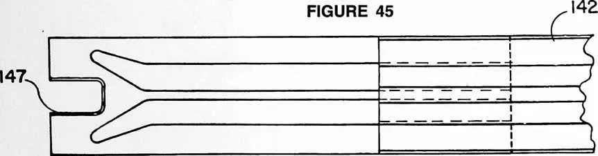

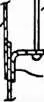
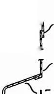

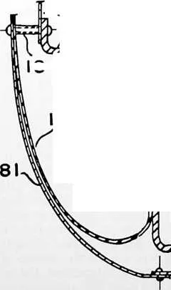

263 ameter than the ring 4, it being of approximately the diameter of the inner cone 109 of the ventilator so as to encompass an area large enough to permit proper flue arrangements going up to the ventilator. The arrangement is such that the carlings radiate in a circumferentially spaced relation from this ring 145 downwardly until their lower ends reach the ring 6; these lower ends have slots 147. These lower ends are, therefore, forked and fit around the parts 74 of the brackets supporting the lower ends of the cowling carlings, this providing ends terminating over the gutter 104 encircling the house beneath the cowling and cowling carlings. Beneath the compression ring 4 these ceiling carlings 142 are supported by brackets 148 having ends 149 which may be slipped into holes 150 formed in the upper parts of the carlings and which have hooked upper ends 151 which may be hooked over the ring 4.
264 The arrangement is such that these ceiling carlings may have their lower ends slipped over the compression ring
265 6, by fitting their slots 147 around the brackets supporting the cowling carlings, and their inner ends then raised for application of the brackets 148 and fastened to the ring 145. Ceiling gores 152 made in the form of sections which flare from their inner to their outer ends, may be supported on top of the ceiling carlings with the gore longitudinal edges adjacent and overlying the centers of the ceiling carlings. The lower ends of these roofing gores are also slotted as required to clear the parts around the ring
266 FIGURE 53
268 FIGURE 54
269 6 so that their lower ends may terminate over the gutter 104. The hooked brackets 148 are small and the holes through which their lower ends 149 are slipped, are preferably positioned in the top portions of the middle upward loops of the carling sections, thus permitting these hooks to pass upwardly through the spaces between the cowling gores. These gores are preferably made of hard plastic sections, or they might be made of plywood or the like. They may be provided with fastenings at their upper and bottom ends so that they may be stretched tautly over the ceiling carlings or they may be preformed as
270 FIGURE 56
271 FIGURE 57
274 FIGURE 58
276 proper curves so that after assembly they provide a ceiling dome. They should be waterproof so that any leakage or condensate, dropping from the inside of the cowling, will be caught by them and guided down into the gutter 104 or into the ceiling carlings which then function as gutters carrying the water to the circular gutter 104.
277 The cowling gores are made of sheet aluminum alloy that is sufficiently thin to permit its being compactly rolled for packaging, and if they possess sufficient flexibility the ceiling gores may be similarly packaged. Otherwise, they may be made in sections which are fastened together during the assembly of the house, with the sections overlapping in a direction preventing water running through the joints. The ceiling carlings may also be made in sections which are fastened together during assembly of the house, like the cowling carlings, and they too are made of aluminum alloy and can inter-nest for packaging most compactly.
278 Returning now to the side wall construction, partly circular sections 153 when assembled provide baseboards around the inside periphery of the house, these sections having their ends overlapped and inter-fastened and being pressed aluminum alloy channel sections with vertical webs and bottom flanges 154 which may be fastened to both the flooring panels 44 and to the deck sections, whereby the fastenings simultaneously position these baseboard sections and prevent outward movement of the flooring panels which would cause them to become loose. The bottom corner between the flange 154 and the upstanding web of the baseboard sections is provided by a fairly large radius curve so as to avoid the formation of comers inside of the house which might catch dirt. The upper flange 155 angles upwardly so that its upper edge terminates beneath the inner edge of the windowsill 91, the sections from which the Tatter are made being smoothly curved downwardly to provide a depending trim skirt 156. A series of air-impervious curtains, such as synthetic leather or rubber of attractive appearance, depend from this trim skirt 156 to the upper edge of the upper flange 155 of the baseboard 153, and may be fastened thereto by snap fasteners or the like so that these curtains may be released and raised when the previously described ventilating panels, forming part of the wall skin, are dropped for ventilation purposes. These curtains 157, in conjunction with the baseboard 153 and the header 105, function to provide a double-walled skin around the entire periphery of the house. If desired, the plastic windows 89 may also be of double thickness.
279 Fly screen panels 158, preferably made of plastic, may be cemented or otherwise fastened in place to close the openings resulting when the ventilator panels are dropped, and by arranging these well inside the double-walled construction beneath the windowsill 91, they are entirely concealed when the curtains 157 are dropped. Incidentally, these curtains may be rolled up and fastened when ventilation is desired.
280 The doorways are also made of aluminum alloy pressed parts and each includes a door frame 159 comprising an assembly of separate angle sections which are inter-fastened to form the door contour, which is preferably with a narrow top and bottom and more widely flaring central section. The webs of these sections are formed so that the sides of the door frame flare outwardly, they being formed by one of the legs of the angle sections. The door outline is formed vertically as a part of a cylinder so as to follow the cylindrical contour of the house side, this outline being provided by the other legs of the angle sections from which the door frame 159 is assembled. These legs forming this outline may be rigidly fastened to sheet-metal sections 160 filling the spaces between the terminating ends of the other wall sections and parts previously described.
281 The door closure comprises an assembly in the form of an outer frame 161 assembled from inwardly facing the trackway 164 following the cylindrical contour of the house. The inner flanges of the door frame 161 are shorter than the outer flanges and are engaged outwardly of the house by equally short flanges of a second door closure frame 165 assembled from lengths of suitably shaped pressed sheet Z-sections, the contour of this frame also following that of the door frame and of the door. The flanges of these Z-sections inwardly of the house are fastened to an inner skin 166, this providing the door with spaced walls with the inner wall and its frame capable of telescoping inside the door closure frame 161, the arrangement being such that when the frame 165 and the skin 166 are pushed or pulled into the frame 161, the door can slide, and when these parts are pushed or pulled toward the door frame they close this door frame, a gasket 167 providing a weathertight seal in conjunction with the wedging action of the parts, and prevent sliding of the door.
282 Cylindrical sections 168 and 169 are respectively fixed to the inner and outer skins 162 and 166, these cylindrical parts being assemblies of sheets which can telescope inside one another so as to function as a guide during
283 FIGURE 60
284 FIGURE 61
286 pressed sheet channel sections, so that their outer flanges extend inwardly, and a skin 162 is fixed to these outer flanges. The door, of course, follows the contour of the door frame. The door frame 161 is suspended by rollers 163 riding a trackway 164 fastened to the outside of the house and extending sufficiently far from the doorway to permit the door closure to ride along this trackway to a position where it is completely free from the door frame, telescopic action of the door closure parts previously described. Compression springs 170 working in telescoped tubes 171, the telescoping sections being respectively fixed to the inner and outer door skins, bias the inner door closure skin and frame inwardly at all times, the center of the door inside the cylindrical sections 168 and 169 being provided with a latch bar 172 which interconnects with the inner skin 168 and projects slidably
287 FIGURE 62
288 £65
289 L65

292 FIGURE 64
293 through the outer skin 162. This latch bar is provided on at least its exterior with a handle 173 so that by pulling on this handle the inner skin 166 and its frame 165 may be pulled outwardly so as to telescope inside the outer door closure part for permitting sliding of the door. The latch bar 172 is provided with detents 174 cooperating with a lock 175 so as to permit its being locked with the inner door skin and its frame either in or out.
294 The bottom of the door closure frame 161 mounts a grooved roller 176 which rides beneath a trackway 171A which extends up into its groove, this preventing the door from swinging outwardly. A further means for locking the door is provided by locking bars 177A that slide transversely in the door frame edge and into holes formed in the edge of the inner door frame 165, in the manner of a bank vault door lock. These bars are reciprocated by connecting arms 177 worked by a lever 178 which may be swung by a locking rotative knob 179, a reinforcement bar 180 providing extra stiffness for the skin section 160 adjacent the shaft of this knob 179. This door closure and door frame may be completely assembled in the factory if desired, or it may be an assembly of parts designed for assembly in the field at the time the house is assembled.
295 There is a depending bottom cowling 181 extending completely around the house, this cowling being an assembly of aluminum alloy strip sections that are fastened together during assembly of the house and arranged with

297 FIGURE 65
298 FIGURE 66
301 FIGURE 67
302 its upper edge fastened to the flange 92 of the outer deck ring 29 by means of rivets or the like provided with spacers 182 so that the upper edge of the cowling is spaced away from the bottom periphery of the house side. This cowling 181 is made from sections formed to give the cowling a cross section wherein the cowling goes vertically downwardly a short distance and then smoothly curves inwardly to a level beneath the bottom of the outer deck ring 29, the cowling functioning aerodynamically to deflect wind blowing against the house side bottom downwardly under the house. The spaced upper edge of this cowling 181 allows water running down the house outside to flow into the inside of this cowling and here a gutter 182A, made of rubber-like material, catches it for disposal as desired. The bottom of the house deck is designed to be spaced a foot or so above the ground.
303 The house is in the form of a perfect cylinder having domed cowling on its top and bottom and with the ventilator on its top well streamlined. Therefore, the house is capable of resisting high wind stresses, its contour providing streamlining no matter which way the wind blows.
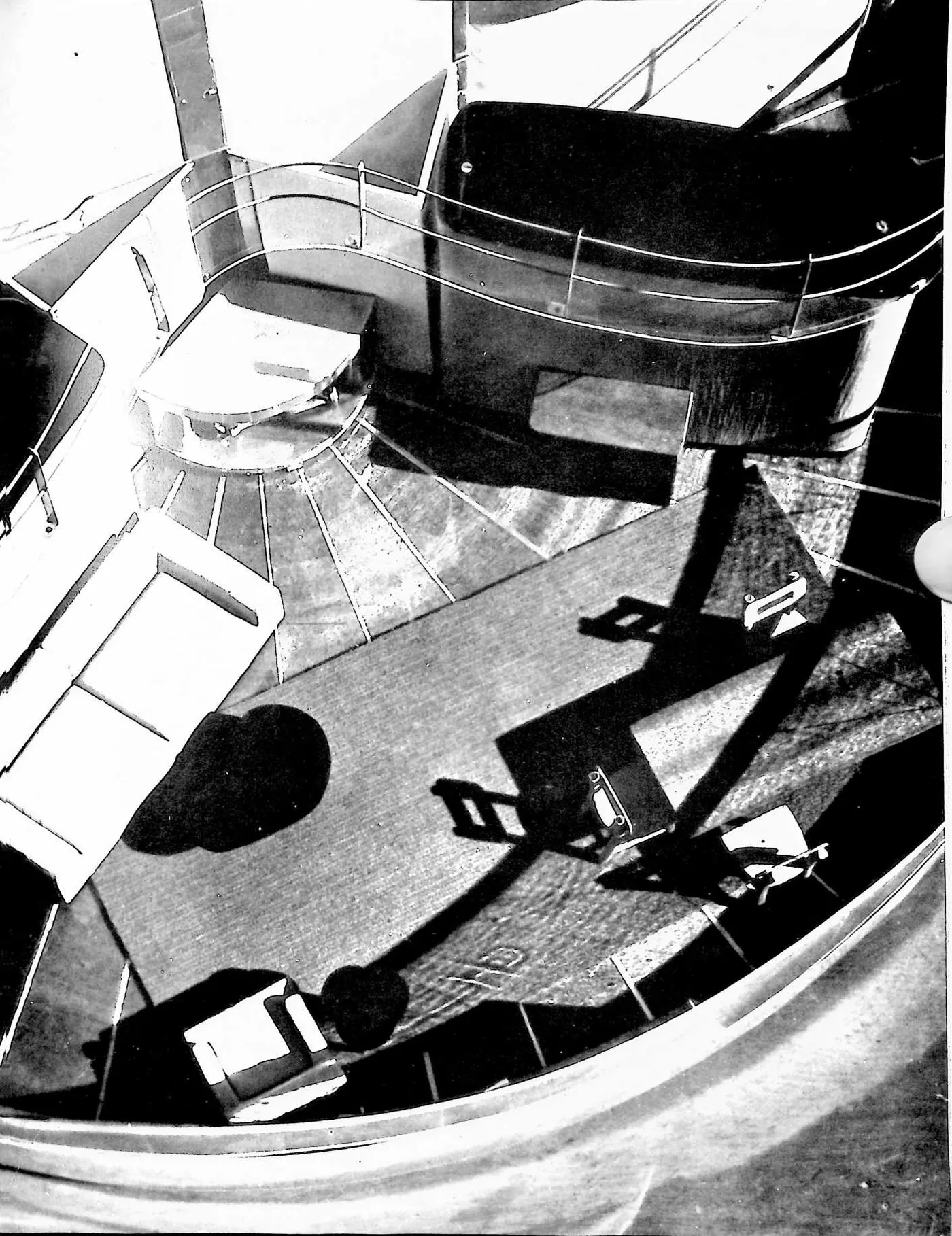
304 The house being described is approximately 36 feet in diameter and provides considerable living space in its interior because of its cylindrical shape. Its inside is equipped with two bathrooms 183 and 184 of the type disclosed in Patent No. 2,220,482, these bathrooms being arranged in tandem on one side of the mast 2 and in conjunction with wall units 185, 186 and 187 dividing half the house into two bedrooms. These wall units 185, 186 and 187 do not extend from the bathrooms completely to the inside of the house wall, but terminate so as to provide spaces of about the widths of usual bedroom doors, thus providing doorways. These doorways are closed, in each instance, by doors 188 which may be of the type consisting of vertically pleated fabricate door closures which slide transversely of the doorway. Door closures of this type are commercially available and have the advantage that they are light in weight and compact for shipping. The wall units separating the bedrooms are not high enough to provide complete wall closures, this being done above each of them by panels 189 that fan outwardly above the units from the mast 2 and which have top edges coinciding in shape with that of the domed ceiling of the house. These panels may be made from aluminum sheet sections or plastic and may take various forms. Preferably they are of a vertically corrugated nature so that they may be made of thin metal yet still be comparatively rigid. As described in the aforementioned patent, the bathrooms are assembly units that may be shipped as compact groups of parts, and the wall units 185, 186 and 187 should be of a similar nature. One example of a suitable wall unit will be presently described.
305 The other half of the house includes the doorways through the house side, of which there are preferably two, each doorway being located relatively close to the wall units 185 and 187 facing away from the sleeping accommodations. Other wall units 190 and 191 are respectively arranged to make comparatively small segregated spaces opposite each door, the unit 190 providing for an entrance hall and the unit 191 providing a kitchen space. The space between the units 190 and 191 provides for a large living room, the attractiveness of which is enhanced by eliminating the ventilating panel, previously described, through a short arc of the living room wall, and bending down the windowsill 91 to encompass a portion fairly close to the desk, this being done by the use of suitably stamped windowsill sections, whereby to provide a large bay window effect 192, using wider transparent sheets to close this bay window 192.
306 Short wall sections 193 and 194 extend inwardly from
309 FIGURE 69
310 159
311 FIGURE 72
313 the inner edges of the units 190 and 191, respectively, to provide triangular spaces 195 and 196, and these spaces are provided with closures 197 and 198, respectively, so that they become vertical ducts extending from deck level to any height desired and which may be used as flues for aiding in the many possible heating and ventilating effects and for other purposes. For example, by having one of these flues opening from the ventilator bottom to the deck bottom, it is possible to prevent or reduce pressure differentials on the house outside even when the wind blows. This greatly reduces the heat loss from the house inside and makes the house more stable during windy conditions. It is unnecessary to provide closing walls above the units 190 and 191 or doors for the passageways between their outer ends and the inside wall of the house.
314 One or more of the wall units may comprise an assembly of structural shapes and sheet-metal skin sections providing a horizontally elongated enclosure internally provided with longitudinally extended upper and lower shafts 199 and 200 respectively positioned close to the top and bottom of the unit. These shafts are journaled to revolve and respectively mount axial spaced sprockets 201 and 202. Chains 203 ride these sprockets, the chains vertically extending from one sprocket to the other in each instance. The sprockets are keyed to at least one of the shafts so that the two radially spaced chains work in unison. Guideways 204 extend parallel and close to the straight sections of the chains 203 and carriages 205, fixed to the chains, mount spaced wheels 206 which ride these guideways 204. These carriages 205 are each in the form of a T with the rollers mounted to the ends of the head of the T and with the leg of the T pivotally fixed, at 207, centrally to a depending, side-opening basket 208. These baskets 208 are rectangular in cross section and their corners are provided with wheels 209 on their top corners at one end and 209A on their bottom corners at the other end, vertical guideways 210 being spaced outwardly from the guideways 204 and parallel to them at the basket end having the wheels 209 and other similar but lower guideways 210A being provided for the other basket end having the wheels 209A, and the wheels on the outsides of the basket, either going up or going down, riding these guideways so that the basket 208 is rigidly positioned against tilting at all times. The guideways 210 and 210A turn inwardly at their tops and bottoms toward the sprocket wheels to guide the wheels for which they are respectively provided as the baskets revolve around the sprocket wheels, it being understood that the curved upper and lower ends of the guideways are all curved properly to permit the baskets to revolve around the sprockets, the baskets being completely rigid while traveling. With this arrangement any of the wall units may be provided with a very great many shelves opening from
315 the same side of the unit, the side of the latter being provided with a single opening coinciding in size and shape with that of the side opening of the various baskets and with which any of the baskets may be registered. The shelves provided by these baskets may be used to store clothing'and the like, which will be much more easily found because it is only necessary to look into a single opening, while the baskets travel past the opening, until the article is found. Any convenient arrangement may be provided for powering one or both of the sprocket shafts to effect the necessary motion, and this may comprise an electric motor controlled from outside the wall unit. All of the parts described will, of course, be capable of assembly in the field or may be shipped as compact subassemblies.
316 These various wall units are made with a horizontal cross section that is in the form of a long oval so that even though the sides of the wall unit are made of very thin-gauged sheet metal they will not cause acoustical diaphragm noises. This principle applies to practically the entire house, all the major surfaces being curved, it following that the house provides for unusual quietness inside it as compared to the conventional house with flat walls. This use of curved surfaces has the further great advantage that the use of very thin-gauge sheet metal is completely practical, the curved surfaces giving it inherent rigidity. Very thin sections are made further practical by the fact that practically everything involved in the construction of the house, that is under any stresses whatsoever, is working in tension, excepting for the compression mast. All of the parts may be made from strong and highly tempered aluminum alloy, such as is used in aircraft construction, excepting for those parts subjected to unusual corrosion or requiring very great tensile strength. It is for this reason that the footing is made largely of stainless steel having an analysis designed particularly to resist corrosion, while the tension strands 3 are made of stainless steel having an analysis designed to provide maximum tensile strength. The use of these high-cost alloys in the construction of the house is economically tolerable only because the manufacture, packaging, and shipping of the house permits full use of mass production methods.
317 Due to the construction of the house there is a well-balanced thermal effect wherein there is practically no uncontrolled heat exchange between the inside of the house and the outside. This result is diminished if there is direct heat conduction between the inside and outside; there-
318 187
321 FIGURE 74
322 fore, wherever there are direct metallic heat-conducting paths it is preferred to break these paths by the use of thermal insulation, such as by the use of nonmetallic washers, inserts, sheets, and the like, depending on which is most effective.
323 It will be noted that there is a peripheral space around the house between the cowling lower edge and the side upper edge through which air may be drawn upwardly along the cowling bottom and out the ventilator, thus decreasing the tendency for condensation on the cowling bottom and reducing heating of the house inside in hot weather. Preferably aluminum foil is fitted over the tension strands, beneath the cowling, at least, by laying it thereon and bending its edges around the strands so as to form an intermediate wall between the cowling and the ceiling, the space between this intermediate foil wall communicating with the just-described peripheral space and the ventilator and confining the air sweeping under the cowling bottom to the space between this foil wall and the cowling. This arrangement provides a dead air space between the foil wall and the ceiling, and the foil acts as an infrared radiation reflector in both directions.
324 The present inventor believes that he is the inventor of this house disclosed herein in its entirety, of the various combinations and sub-combinations, and the various parts, and it is his intention to claim the house entirely, its various combinations and sub-combinations of parts and the parts themselves. The aerodynamic and thermal effects inside and outside of the house are his inventions, both as specifically described and as they are inherent, and the general conception of a house working dynamically like a machine in carrying the various loading stresses, and in coping with the elements and forces that must be handled by a completely satisfactory house, are all this inventor’s conceptions, and this inventor intends to claim them, and all the rest, in every possible lawful manner. If the appended claims fail to cover every one of these phases and all possible other phases, and all equivalents of what is disclosed herein, specifically or inferentially, it is because of accident, inadvertence, or mistake, and not through intent.