
25 NON-SYMMETRICAL TENSEGRITY (1975)
2U.S. PATENT—3,866,366
PATENTED—FEBRUARY 18, 1975
3 FIGURE 1
4 20-24
5 Ist TIER
6 30-34j
7 ZTIER
8 40-44
9 3rdTI ER
10 5Q-54rSs=D=s=a 4thuER
11 FIGURE 2
13 ■received a commission in 1969 from St.
14 Peter’s College in Oxford, England, to design a theater. They wished to have a portable theater, and I found that such a portable theater called for a more or less cylindrical form with proper doming and proper bowing of the bottom for the audience and stage. Because the portable theater also needed to be very light, I wished to use tensegrity structuring, which meant that the tensegrity structuring would not be symmetrically formed as I had been using it in the geodesic dome. It would be what I called asymmetrical. I found it quite possible to make the asymmetrical tensegrity.
15 FIGURE 5
17 UNITED STATES PATENT OFFICE
18 NON-SYMMETRICAL TENSION-INTEGRITY STRUCTURES
19 This invention relates to building structures and particularly to one of the tension-integrity types of structure.
20 The present invention is an improvement on and a variation of tension-integrity structures, such as shown in prior U.S. Patent No. 3,063,521, Nov. 13, 1962. The structures involved are known generally as geodesic-type dome structures. The tension-integrity structure is one that is of generally spherical form having discontinuous compression columns joined with tension elements in a manner to provide the aspect of discontinuous compression and continuous tension sometimes referred to as ‘‘Tensegrity’’ structures. In some instances, it has been found desirable in a structure of the type involved herein to have rectangular-like areas or zones for windows, walls, doors, or the like.
21 One of the objects of the present invention is to provide an improved tension-integrity type structure having zones of rectangular-like configuration.
22 Another of the objects of the invention is to provide a tension-integrity type of structure wherein a portion can be prefabricated.
23 In one aspect of the invention and in the form shown, the generally spherical-like building structure can have a substructure at the top and a substructure at the bottom.
25 the bases of the substructures being spaced from each other, the bases being of pentagonal configuration which are twisted relative to each other in a manner to provide rectangular-like facets therebetween. The substructures and spacing of the pentagonal configuration, which are lesser circles as compared with great circles, are formed by a plurality of column-like compression members joined by a plurality of tension elements, such as wire or rope, the column-like members being axially spaced relative to each other by the tension elements which are attached near the ends of spaced column-like members. The pentagon of the top substructure above the aforementioned lesser circle has five column-like members forming a generally pentagonal configuration. The bottom substructure has five column-like members in a pentagonal configuration and below its lesser circle which is the reverse of the top pentagon. Column-like members extend between the two substructures and are joined thereto with tension elements, the reversal of the top and bottom pentagons resulting in the twisting of the lesser circle pentagons relative to each other. It is to be understood that various frequencies can be used and various types of enclosures or panels employed.
26 Other objects, advantages and features of the present invention will become apparent from the accompanying description and drawings, which are merely exemplary.
27 In the drawings:
28 Fig. 1 represents four tiers, the top two representing the top substructure and the lower two representing the lower substructure;
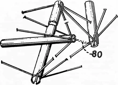
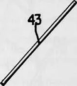
29 Fig. 2 is a fragmentary perspective of a column-like member with four tension elements attached adjacent the ends thereof for attachment to other column-like members;
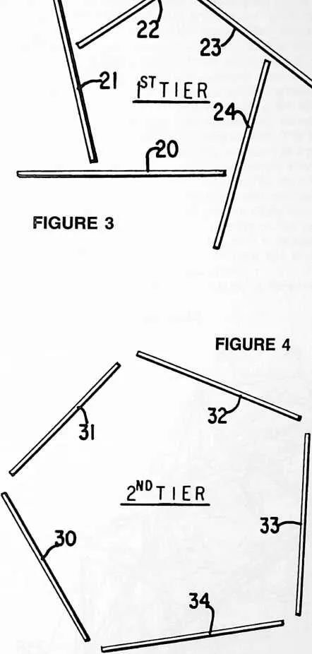
30 Fig. 3 is a schematic representation of the relationship of the column-like members of the top pentagonal configuration;
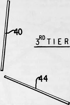
31 Fig. 4 is a schematic representation of the upper substructure pentagonal lesser circle or base;
32 Fig. 5 is a schematic representation of the lower substructure pentagonal lesser circle or base showing the same in its rotated position relative to the lesser circle pentagon of Fig. 4;
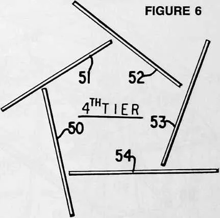
33 Fig. 6 is a schematic representation of the column-like members of the bottom pentagonal configuration which is similar to Fig. 3 but is in a reversed relationship; Fig. 7 is a top view showing generally the manner in which the column-like members appear;
34 50B
36 278
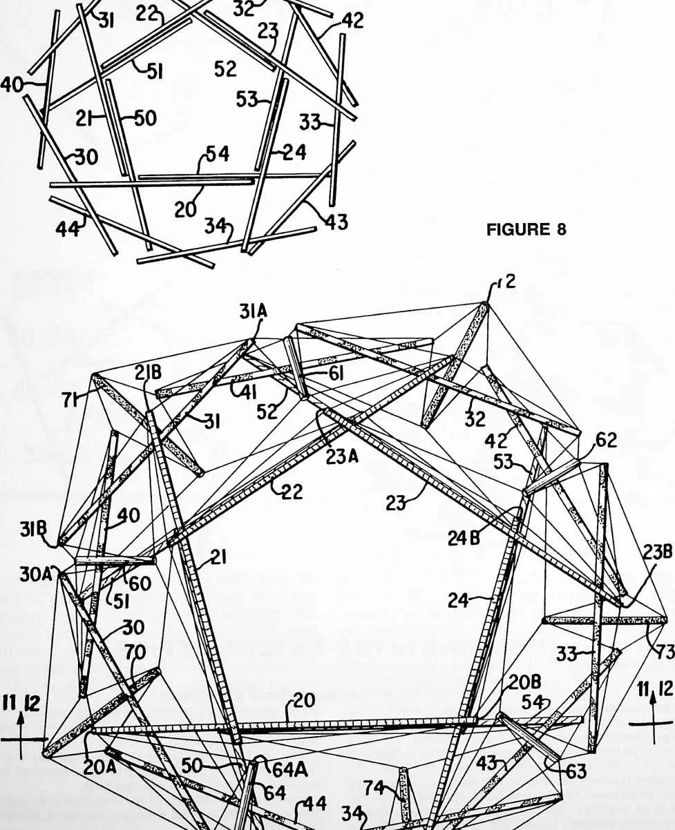
38 Fig. 8 is a top view generally similar to Fig. 7 but showing the tension elements between the column-like members;
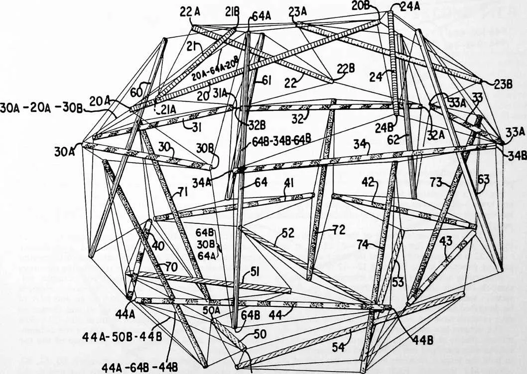
39 Fig. 9 is a perspective side view of Fig. 8 taken in the general direction 9--9 of Fig. 8;
40 Fig. 10 is an enlarged fragmentary view of the upper and lower vertical columns together with related columns and tension elements, there being five of each around the periphery;
41 Fig. 11 is a fragmentary view of the top substructure looking generally in the direction 11--11 of Fig. 8; and
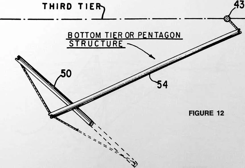
42 Fig. 12 is a fragmentary view of the lower substructure looking generally in the direction 12--12 of Fig. 8.
43 Proceeding next to the drawings wherein like reference symbols indicate the same parts throughout the various views, a specific embodiment of the present invention will be described in detail. In the interest of simplicity, reference symbols have not been included in all of the figures.
44 The column-like members can be made of wood, aluminum, plastic or any suitable material. The ends of the column-like members can be notched or otherwise fitted to hold the tension elements or wires at the ends of said column-like members. Each column-like member will have four tension elements emanating from each end thereof as shown in Figs. 2 and 10.
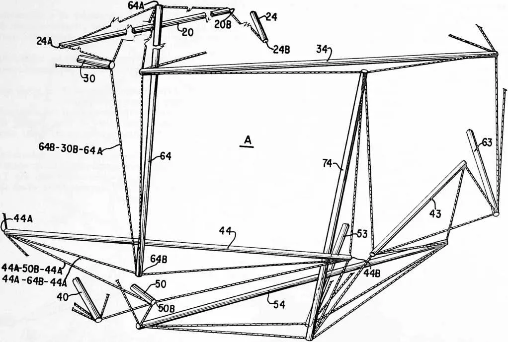
45 In Figs. 3, 4, 5 and 6, for purposes of description, the general relation of the column-like members before they are joined together with the tension elements is shown. As can be seen, the top pentagonal configuration, illustrated in Fig. 3, is oriented in a clockwise configuration as compared with the counterclockwise configuration of the bottom pentagonal configuration shown in Fig. 6. As will be explained hereafter, the upper substructure base lesser circle pentagon configuration of Fig. 4 is twisted in the final assembled structure relative to the lower base lesser circle pentagon configuration of Fig. 5.
46 Fig. 7 illustrates the relation of the members in the final assembled structure, the elements of Figs. 3 to 6 being combined therein.
47 Referring now particularly to Figs. 8 and 9, the top pentagonal configuration will be described. Column-like members 20, 21, 22, 23 and 24 are attached or supported by tension elements to other of the column-like members so as to be axially spaced therefrom. For example, column-like member 20 has a tension element 20A-64A-20B leading from end 20A to an end 64A of vertical column-like member 64 (Fig. 9) and thence to end 20B. Additionally, a tension element 30A-20A-30B from end 20A to end 30A and end 30B of the column-like member 30 of the lesser circle pentagon of the top substructure.
48 Vertically extending column-like members 60, 61, 62, 63, 64 extend between tension elements fastened to the column-like members 40, 41, 42, 43 and 44 of the lower substructure lesser circle pentagon and tension members between their opposite ends and column-like members of the top pentagon configuration column-like members 20, 21, 22, 23, 24.
49 Similarly, vertically extending column-like members 70, 71, 72, 73, 74 extend from tension elements attached
50 24
51 TOP TIER OR PENTAGON STRUCTURE
52 UH il
53 I I./
54 ■30
55 SECOND TIER
56 to the ends of the upper lesser circle pentagon members 30, 31, 32, 33, 34 and tension members attached to column-like members 50, 51, 52, 53, and 54 of the lower pentagonal configuration.
57 The lower pentagonal configuration is similar to the top configuration except that it is reversed, as can be seen in Figs. 3 and 6.
58 In Fig. 10, the column-like members are numbered so as to agree with Figs. 8 and 9. One set of members will be described, the others being similar thereto. Upwardly extending member 64 has end 64B connected to member 44 of the lower lesser circle pentagon by tension element 44A-64B-44B. End 64B of member 64 is also connected to end 30B of upper lesser circle pentagon member 30 and
60 end 64A by tension element 64B-30B-64A as well as to lesser circle member 34 by tension element 64B-30B-64A. The upper end 64A of 64 also is connected to the ends of the upper pentagonal configuration member 20 by tension element 20A-64A-20B. The end 50B of member 50 connects to member 44 by tension element 44A-50B-44B. There are five lower and five upper vertical column-like members repeated in a similar manner. The term ‘‘vertical’’ means generally vertical when the structure is oriented as shown.
61 It can be seen that the column-like compression members are held in axially spaced relation to each other by the tension elements.
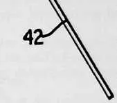
62 As a result of the combination of column-like elements and tension elements shown and described, there will be rectangular-like facets such as depicted at A (Fig. 10) between the upper lesser circle including elements 30, 31, 32, 33, 34 and the lower lesser circle formed by elements 40, 41, 42, 43 , 44.
63 Figs. 11 and 12 show the relation of 3 of the elements of the top tier and of the bottom tier.
64 As seen in Fig. 2, a loose connecting wire or elements 80 can be used so as to limit outward movement.
65 Merely by way of example, the structure of the present invention can be formed of thirty aluminum struts or column-like members, each 36% inches long and 1 inch outside diameter with one-fourth inch slots formed in each end thereof for receiving the tension elements. The tension elements can be made of synthetic fiber line having a length of about 37’/2 inches between ends of the column-like member, there being a distance of about 5 inches from the middle point of the tension element to the column-like member when the line is stretched tight and engages other elements of the combination. It is understood that these dimensions will vary according to material of the line or rope and other dimensions of the structure. Also, the tension elements combination can be prefabricated and the column-like members inserted therein when and where the structure is to be erected.
66 It will be understood that various details of construction and arrangement of parts may be changed without departing from the spirit of the invention except as defined in the claims.