
13 CATENARY (GEODESIC TENT) (1959)
2U.S. PATENT—2,914,074
APPLICATION—MARCH 1, 1957
SERIAL NO.—643,403
3 162
4 PATENTED—NOVEMBER 24, 1959
5 Geodesic domes, 1144 feet in magnitude, made out of aluminum or steel tubular struts and hubs, were used for the United States international trade fair domes. We found it appropriate to produce fabric tents with the fabric cut out very economically in geodesic patterns, which patterning would produce a tent with vertexes corresponding to vertexes of the tubular dome structure but a little bit smaller than the structure. With the fabric so cut out to produce hyperbolic paraboloid surfaces with conic convergences corresponding to the vertexes of the geodesic tubular frame, we found it possible to mount powerful aluminum pads at the vertexes of the parabolic cones of the fabric to distribute the stress. We then had stainless steel chains emanating outwardly from the tent (from the center of each of the circular reinforcing at the outer end of the parabolic cones). We then found it appropriate to make keyholes in the hubs of the outer tubular geodesic dome to which the stainless steel chain pattern could be pulled outwardly by individuals climbing on the outside of the tubular dome. In this way we were able to stretch the interior tent outwardly toward the tubular geodesic frame. Due to the hyperbolic paraboloid surfaces the dome would
7 never flutter in any wind. This proved to be extremely satisfactory for a number of the international trade fair domes.
8 One of these trade fair domes ended up in Alaska and went undamaged through several winters with heavy snow-loadings until it was ultimately dismantled.
9 UNITED STATES PATENT OFFICE
10 Richard Buckminster Fuller, Forest Hills, N.Y.
11 GEODESIC TENT
12 This invention relates to geodesic building structures in the form of spherical tents.
14 Heretofore, as described in my prior Patent No. 2,682,235, granted June 29, 1954, I have discovered how to create building structures in which the main structural elements are interconnected in a geodesic pattern of approximately great circle arcs intersecting to form a three-way grid of substantially equilateral triangles. Such building structures may consist of skeletal frameworks made of interconnected struts, or of interlocking or interconnected sheets or plates, or of molded plastic sections fastened together along flanged edges, or of flexible fabrics or plastic skins conforming in pattern or behavior to the three-way grid geodesic construction. Also I had found that a very special relationship exists between a geodesic building structure made of interconnected struts and a complementary geodesic building structure made of flexible fabrics or plastic skins where these two structural components are made to conform in structure, pattern, or behavior to a mutual three-way great circle synergy. My present invention is concerned with an improved geodesic skin or tent construction which gives a new and synergetic stress distribution—synergetic in the sense that the behavior of the skin under stress is unpredicted by its several parts, and that there is imparted to the structure a strength beyond that which would be calculated using accepted values of strengths of materials and usual methods of stress analysis and computation. Fundamentally, I accomplish improved results by ‘‘tailoring’’ the several pieces which go to make up the tent in such a fashion as to yield an omni-triangulated suspension pattern. The pieces themselves may or may not be of generally triangular form, but the suspension pattern should be so in any case. The tailoring is such as to include an omni-triangulated pattern of suspension points extending over substantially the entire area of the tent, with a predetermined dip in the fabric between one suspension point and another. This dip produces a catenary curve, or an approximation thereof, between each pair of adjacent suspension points. Around each point of suspension the structural form is essentially that generated by revolution of a catenary segment about the catenary suspension point. This form approximates a cone and for simplicity is sometimes referred to herein as ‘‘conical.’’ In some instances a truly conical form can be used, so I employ the term ‘‘conical’’ as including both a true cone and such pyramidal or catenary forms as will be described with reference to the several exemplary embodiments shown in my drawings.
15 Description
16 The accompanying drawings illustrate the best mode contemplated by me for carrying out my invention according to several preferred embodiments thereof.
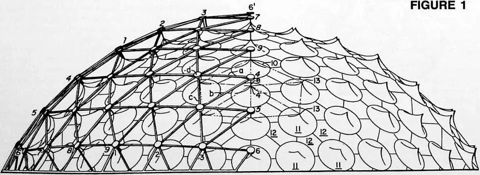
17 Fig. 1 is a side elevational view of a domical structure embodying the invention. It shows an exterior geodesic framework with a geodesic tent supported within it. Part of the frame has been removed to show more clearly the catenary form of the tent.
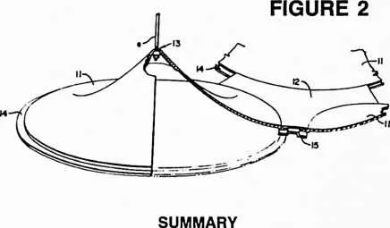
18 Fig. 2 is a detail perspective view of one of the conical elements of the structure together with one of the connecting pieces of generally triangular, or diaper, form, and adjoining portions of other conical elements.
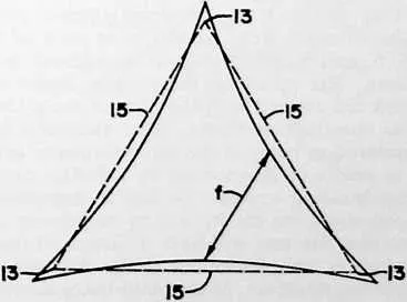
19 Fig. 3 is a detail view of a triangular piece for a tent of modified construction.
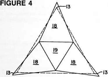
20 Fig. 4 is a detail view of an assembly of flat triangular pieces for a tent of another modified construction.
21 Fig. 5 is a schematic diagram illustrating the fundamental stress pattern of the several catenary constructions of Figs. 1 to 4 inclusive.
22 Fig. 6 is a comparative sketch to show (by correlation with Fig. 5) the relationship between the cone-diaper
24 FIGURE 3
25 form of Figs. 1--2 and the approximation of that form with the use of flat pieces of tent material according to Fig. 4.
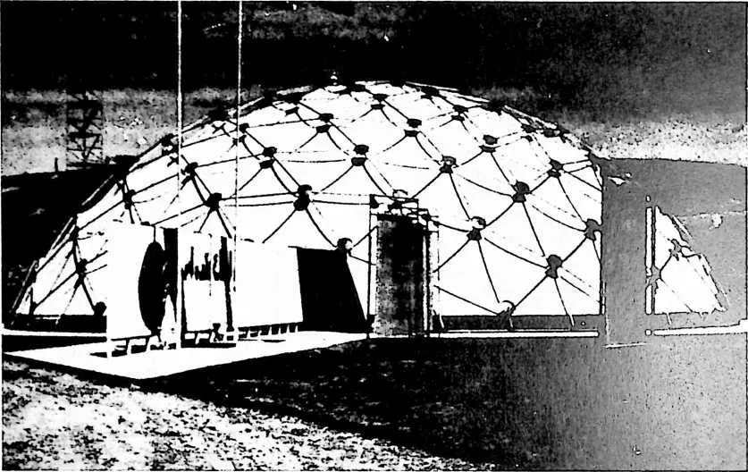
26 Fig. 7 is a photographic reproduction of a completed dome in which the tent structure is made of tailored triangles of the general form typified in Fig. 3.
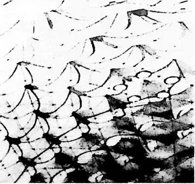
27 Fig. 8 is a photographic reproduction of a portion of the interior of a tent made of tailored triangles of the general form typified in Fig. 4.
28 Reference is made to Fig. 1 which shows a geodesic building structure made of interconnected struts and a complementary geodesic building structure in the form of a tent supported within the first named structure. A portion of the outer building structure has been removed to show more clearly the catenary form of the tent. The framework of the outer supporting structure is constructed on the pattern which I have described as comprising approximately great circle arcs intersecting to
30 form a three-way grid of substantially equilateral triangles. In the particular embodiment selected for illustration, the three-way grids are formed on the faces of a spherical icosahedron. Each of the equal spherical equilateral triangles of this construction is modularly divided along its edges. Great circle arcs connecting these modularly divided edges in a three-way great circle grid provide the outline for the plan of construction. Thus on the spherical equilateral triangle shown at 6, 6, 6' in Fig. 1, we have a series of great circle arcs 1--1, 2--2, 3--3 etc., a second series of great circle arcs 4--4, 5--5, 6--6 etc., and a third series of great circle arcs 7--7, 8--8, 9--9 etc., each series paralleling one of the sides of the spherical triangle 6, 6, 6', and the three series of arcs intersecting to form an omni-triangulated pattern in which the triangles form pentagons at each of the vertexes, 6, 6, and 6', and hexagons throughout the rest of the pattern. The structural members a, b and c of the framework are aligned with the lines of the grids. In the particular construction shown, these structural members are considered as being in the form of tubular struts connected at points of intersection by hub-like members d. The inner building structure or tent is suspended within this framework from the hubs d by suspension cords or rods e so that the tent will have a pattern of suspension points which is complementary to the three-way grid of the supporting structure. In the omni-triangulated pattern of the tent structure, the broken line 10 represents a hexagon centered on suspension point 4' located radially inward from suspension point 4 of the outer supporting framework (radially with reference to the center of the spherical icosahedron).
31 In the embodiment of Figs. 1 and 2, the tent is made up of conical pieces 11 and connecting pieces 12 of generally triangular or diaper form. The conical pieces are essentially of the form generated by revolution of a catenary segment about the catenary suspension point, so the apexes of the generated forms constitute the suspension points and these are arranged in accordance with the described geodesic three-way grid pattern. In this way I have provided a tent of generally spherical form tailored to an omni-triangulated pattern of projecting points of suspension formed by the apexes of forms generated by revolution of catenary segments about the respective catenary suspension points. The spaces between the circular edges of the conical pieces are filled in by the diapers 12 which may be fastened adhesively or otherwise to flanges
- 14.
- at the bases of the conical pieces. Also, if desired, and as shown in Fig. 2, there may be connecting members 15 between the edges of adjacent diapers 12 and cones 11.
32 I have discovered that this construction results in the creation of what may be described as an inner sphere: regarding the several suspension points 13 as defining a sphere which I shall here refer to as the outer sphere, I find that the interconnected diapers 12 become stressed to the form of an inner sphere. Thus the tent structure as a whole uniquely combines the inwardly dipping catenary suspension lines between the omni-triangulated pattern of suspension points with the outwardly curved fabric of the ‘‘inner sphere.’’ I have found that this combination of inwardly and outwardly curving lines of stress produces a tent of surprising strength and rigidity. Even when formed of the thinnest nylon skins, the tent is characterized by high strength and freedom from fluttering in the wind. A hypothesis for the behavior of fabric tents supported in geodesic frames may be made with reference to the schematic diagram of Fig. 5. The lines of stress may be said to flow in natural radial catenary lines
- 15.
- outwardly and downwardly from the points of suspension 13. These radial catenary lines immediately and precessively induce circular lines, or rings, 16 at 90° to their respective axial cones to which the radial lines distribute their loading. These rings then precessively beget in turn further outwardly radial lines, and the radial lines again precessively beget circumferential rings. I believe that this fundamental precessive regeneration may be compared with the behavior of circular wave propagation, so that my tent is capable of distributing loads in the most nearly even energy distribution outwardly to the largest rings surrounding each vertex or point of suspension. When the outermost rings of the series of concentric rings
- 16.
- formed in response to the vertex stressing finally become tangent to one another on the lines 17, they form a tangential hexagon and pentagon network throughout the whole geodesic tent whereby all loads are shared three ways by the synergetic three-way grid of omni-triangulated geodesic great circle system lines. While I have here suggested what presently seems to me to be the best possible explanation of observed surprise characteristics of my tent construction, I do not wish to be limited to this or any particular hypothesis of theory of stress behavior.
33 Another thing I have observed is that if a tent is constructed along geodesic lines, but without tailoring-in the catenary construction and without recognition of the inner sphere, there is created a natural tendency for the fabric of the tent to stretch into shapes somewhat approaching catenary curves. Such stretching thins out the fabric and weakens it, further demonstrating the value of providing a predetermined cone-catenary construction.
34 In Fig. 5 it will be noticed that the radial lines 15 between three adjacent suspension points 13 form a triangular figure comprised of three catenary curves. This figure is shown in Fig. 3. The dotted lines represent straight lines adjoining the three points of suspension 13, and may also be understood as representing each of the catenary curves 15 as seen from above in spherical plan view. When the fabric within the three catenary borders 15 is flattened out, we get a shape approximately as shown in the full lines in Fig. 3. Notice that the distance along a line f between two of the concavely curved edges appears shorter than that between the sides of the dotted triangle. This is because line f is approximately in the plane of the smaller inner sphere. However the fabric when laid out flat to the full line position of Fig. 3 extends beyond the corners of the suspension points 13. According to another embodiment of my invention, a tent of the basic cone-catenary construction is made up of triangular pieces of the form shown in Fig. 3, seamed together along their concavely curved edges to produce the structure illustrated in Fig. 7. In this view the shadows cast by the outer supporting framework on the nylon fabric of the tent reveal approximately the cone-catenary form of the tent. Fig. 7 represents a practical example of the utility and value of my tent construction as it has been applied to an 8,000 square foot geodesic dome which was erected for the United States Government pavilion at the International Trade Fair in Kabul, Afghanistan. The tent was seamed together from the triangular pieces of nylon of the form shown in Fig. 3. The fundamental characteristics of this modified construction are essentially the same as have been described with reference to the embodiment of Figs. 1 and 2, and the schematic diagram of Fig. 5.
35 According to another embodiment of my invention illustrated in Fig. 4, a similar result is attained by tailoring
36 FIGURE 5
37 FIGURE 6
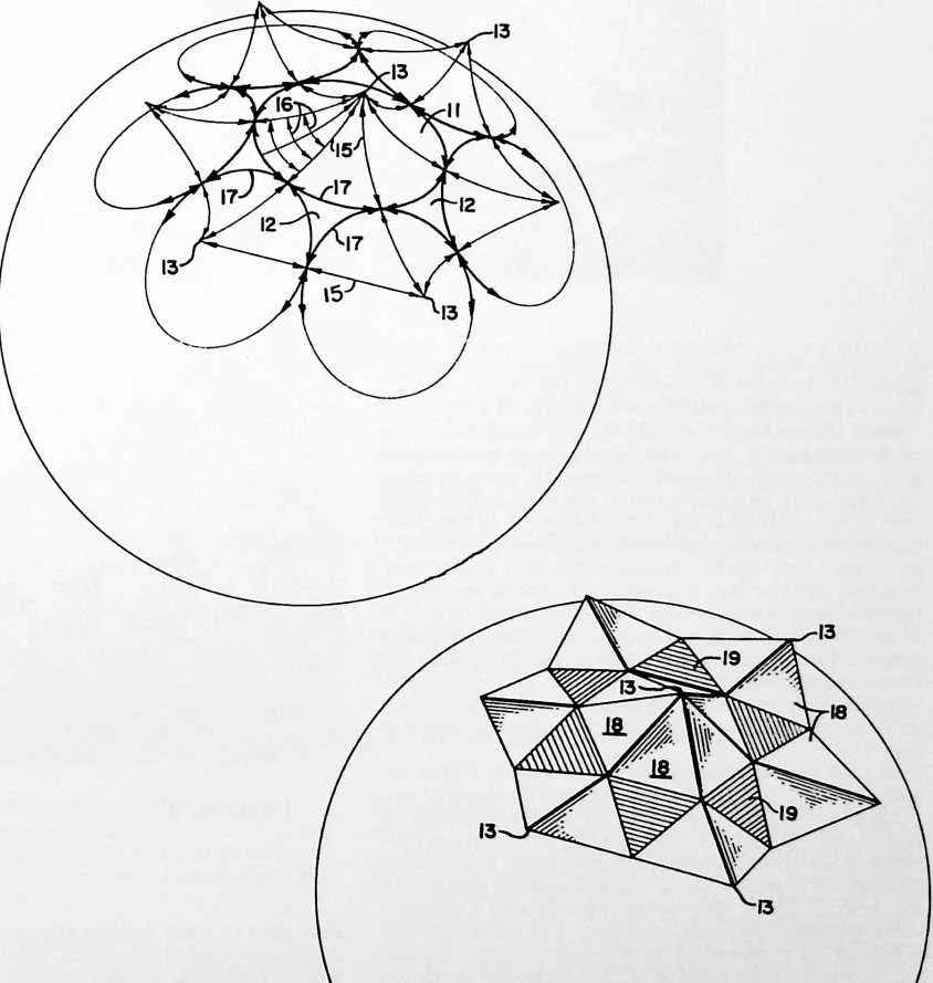
40 a catenary triangle from four flat triangles seamed together in the pattern shown here. The three outer triangles 18 constitute one-sixth or one-fifth of a pyramidal ‘‘cone’’ (depending on whether they are centered on one of the hexagons or one of the pentagons of the three-way grid system), and the center triangle 19 forms in effect the connecting piece or diaper of the Figs. 1--2 construction. In the diagram of Fig. 6, the ‘‘diapers’’ 19 have been shaded for easy recognition. By comparing Figs. 5 and 6, the basic equivalence between the cone-diaper construction and the Fig. 4 construction can be readily discerned. How closely the flat triangular pieces 18 and 19 of the Fig. 4 construction approximate the cone-diaper construction in terms of its effectiveness in creating the cone-catenary pattern is revealed in Fig. 8. This is a photographic view showing a portion of the interior of a tent made of tailored triangles of the general form typified in Fig. 4.
41 In each of the three specific embodiments I have described, it will be seen that the tent has a pattern of suspension points extending uniformly over substantially its entire area; in each the tent is tailored to dip inwardly between adjacent suspension points; each conforms to the omni-triangulated three-way grid pattern; and in each the inward dip of the fabric approximates a catenary curve between one suspension point and another. Other points or correspondence between the several embodiments may be discovered from the description which has preceded. The pieces which go to make up the tent may be fabricated in a variety of ways from thin flexible fabrics such as nylon skins, or from less flexible materials, or in some cases from rigid materials, as may be desired. The pieces may be stitched, glued or otherwise fastened together. They may be cut from fabric according to the patterns of Figs. 3 or 4, or they may be made in molded
43 FIGURE 8
44 fiber glass or other molded materials in the form of Fig. 2. Thus in general the pieces which go to make up the tent may be either molded or made from flat sheet material, and in either case may be of any desired thickness and flexibility.
45 The terms and expressions which I have employed are used in a descriptive and not a limiting sense, and I have no intention of excluding such equivalents of the invention described, or portions thereof, as fall within the scope of the claims.