
20 OCTA SPINNER (1965)
2Using a machine, I found we could produce octahedra, which have twelve edges, in such a manner that the length of any one of the twelve edges could vary, because the octahedron has six vertices, therefore three axes, and the octahedron could be spun on any one of those three axes. You can spin sheet metal to be bent into angular sections to produce a stiff octahedron.
3 Octahedra joined together edge to edge produce tetrahedral bases/faces between them, so octahedra can be joined together, to produce the octet truss. I did not go through with the octet spinner patent after filing because the expense of patent work is very great, and I’m not in the manufacturing world, and I felt that it would not be worth carrying any further.
5 PATENT APPLICATION OF
RICHARD BUCKMINSTER FULLER
FOR
METHOD AND APPARATUS FOR MAKING
THREE-DIMENSIONAL TRUSS COMPONENTS
6 Case 349.021
7 The invention relates to the fabrication of building trusses and components thereof.
8 In my co-pending application for Patent, Serial No. 416,228, filed December 7, 1964, I have described a truss construction which is capable of utilizing more efficiently the tensile strengths of the materials from which the truss is constructed. In such construction, it has been found possible to use many elements loaded purely in tension, indeed, one in which such purely tensioned elements predominate so that relatively few compression members are needed. The construction is one in which a plurality of
10 FIGURE 3
11 units, conveniently made of criss-crossed struts bound together by a network of tension elements, form the basic components, or ‘‘building blocks’’ used in putting together the truss. While such truss components, once assembled, are self-contained units that are easy to handle, their fabrication can become rather complex due to the fact that they are made up of compression struts which are virtually suspended in a network of wire. During fabrication, it is essential to maintain the proper angular relationship between the criss-crossed struts, and the relative dispositions of the ends of the struts for a given predetermined angular relation.
12 My present invention is concerned with the solution of the particular problems involved in the fabrication of these peculiar strut-and-wire components such as those exemplified in my prior application aforesaid, and to the means by which such components may be interconnected to form a building truss.
13 According to a preferred form of my invention, the truss structure produced comprises a plurality of interconnected three-dimensional components each of which has a plurality of struts and flexible edge portions extending between the ends of the struts to form an initially self-supporting unit. The plurality of such components is joined together by connecting the ends of the struts of one component to the ends of the struts of adjacent components through partly spherical fastening elements perforated by a plurality of apertures providing selective adjustment of the angular relationship between the struts of the interconnected components.
14 Fabrication of the truss components comprises the steps of arranging the struts in predetermined angular relation to one another to form a preliminary strut assembly, rotating the strut assembly, feeding a wire for attachment to the ends of the struts, and producing relative movements between the rotating strut assembly and the wire feed to bring the wire into engagement with first one strut and then another and thus form the flexible edge portions of the truss component. My apparatus includes means for performing these several steps in the desired sequence, and for programming the wire feeding device according to predetermined design patterns for components of varying form.
15 The invention has particular application to the fabrication of components of octahedral form comprising eight triangular faces. The eight triangular faces are defined by the wire network, and there are three compression struts which are arranged along the three axes of the octahedron.
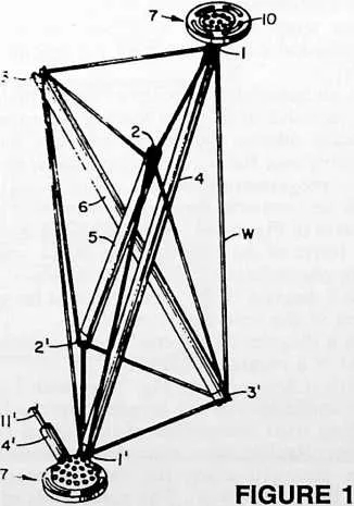
16 In the drawings, wherein I have illustrated the best mode contemplated by me for carrying out my invention:
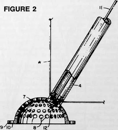
17 Fig. 1 is a perspective view of an octahedral component fabricated in accordance with the invention.
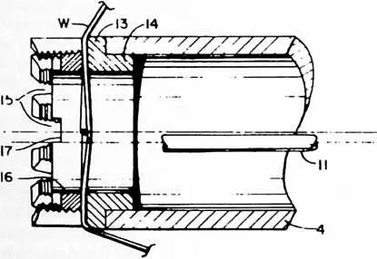
18 Fig. 2 is a detail sectional view showing the partly spherical fastening element secured to an end of one of the struts of the component of Fig. 1.
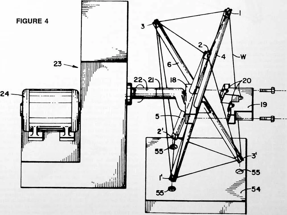
19 Fig. 3 is an enlarged detail view showing an end portion of one of the struts in longitudinal section, with associated wire-fastening means.
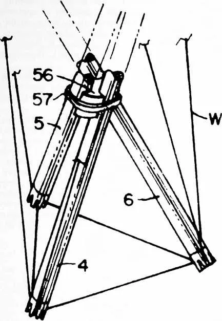
20 Fig. 4 is an isometric perspective view of the apparatus which ‘‘spins’’ the wire on the struts.
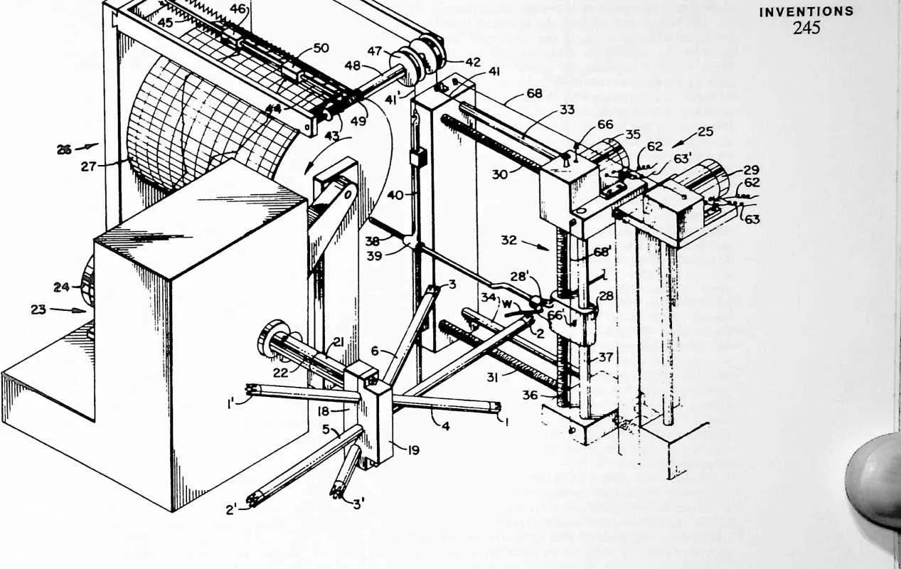
21 Fig. 5 is a detail view of an optional form of means for binding the struts together after removal of the completed octahedral component from the spinning apparatus.
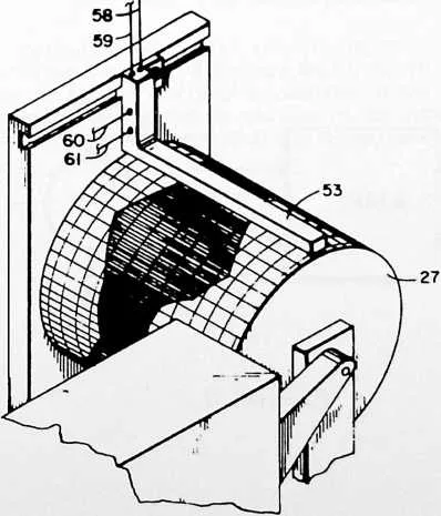
22 Fig. 6 is an isometric perspective view of the apparatus of Fig. 4, inclusive of the wire feeding means and means for producing relative movements between the rotating strut assembly and the wire feeding means, in combination with a programming control means.
23 Fig. 7 is an isometric perspective view of a portion of the apparatus of Fig. 6 as it appears following removal of the stylus frame of the programming device and substitution of the photoelectric ‘‘playback’’ device.
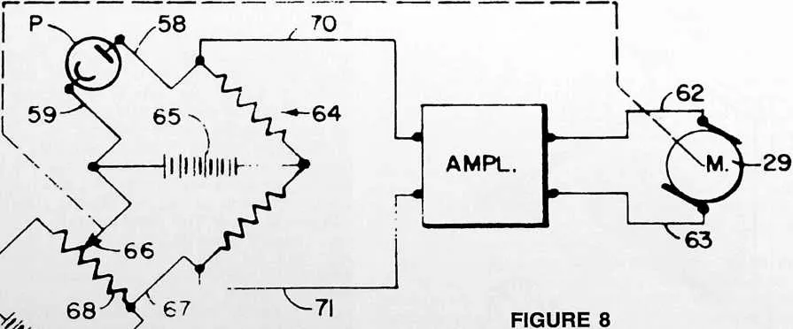
24 Fig. 8 is a diagram of the control circuit for one of the two motors of the wire feed control.
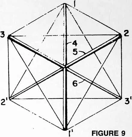
25 Fig. 9 is a diagram of a special case in which the truss component is a regular octahedron.
26 Reference is first made to Fig. 1 in which I have illustrated the application of my invention to the fabrication of a building truss component of octahedral form. This component comprises three compression struts 4, 5 and 6 which are arranged along the three axes of the octahedron, 1--1', 2--2', 3--3'. The upper ends of the compression struts 4, 5 and 6 lie in one plane and the lower ends lie in another plane below the first. The seemingly complex but truly simple form of the octahedral unit will
27 be understood by identifying the faces of the octahedra, the tension elements and the compression struts as follows:
28 Eight faces of the octahedra:
- 1.
- 2-3 1-2'-3
29 l'-2'-3' 1--2'-3'
30 1-2-3' l'-2-3'
31 1-2-3 l'-2'-3
|
Twelve
tension
elements:
| |
|
341--2 |
351--22' |
|
362--3 |
371--3' |
|
383--1 |
392--3' |
|
40l'-2' |
412--1' |
|
422'-3' |
433--1' |
|
443'-l' |
453--2' |
52 Three compression struts:
53 4 5 6
54 From the foregoing tabulation of the truss elements, the student of this disclosure will appreciate the preponderance in tension elements over compression elements and the significant improvement thus obtained in the direction of increased utilization of the high tensile properties of the improved materials and alloys available today.
55 In the preferred construction shown, we have a three-dimensional truss component having a plurality of struts 4, 5 and 6 and flexible edge portions extending between the ends of the struts, these being the twelve tension elements as listed above. The struts 4, 5 and 6 are comprised of tubular members. Partly spherical fastening elements 7 are secured to selected ends of the struts for connection to selected ends of the struts of similar components in forming a truss structure. The spherical fastening elements 7 are perforated with a plurality of apertures 8, Fig. 2, and are secured to the struts by means of the tension wire 11 extending through the tubular members and through selected ones of the apertures 8. Wires 11 are stressed in tension, as by means of nuts 12 threaded onto the ends thereof.
56 The fastening elements may be provided with flanges 9 in which are formed arcuate slots 10 for securement to cladding sheets such as described in my co-pending application aforesaid.
57 The wire W is attached to the ends of the struts in any suitable manner, preferably by the means shown in Fig. 3. Here a collar 13, provided with an attaching flange 14 is suitably secured to each end of the strut as by welding or brazing. Collar 13 is interiorly threaded as shown, and is castellated to provide tapered notches 15 to receive and position the wire W as it is spun onto the strut complex. Thereafter a locking ring 16, having suitable notches 17 for engagement by a tightening wrench is secured into the end of collar 13 for clamping the wire into engagement with the bases of the notches 15 wherever the wire W lies.
59 FIGURE 5
61 Notice that the wire crosses each end of each strut twice. The partly spherical fastening elements 7 are fastened to selected ends of the struts after the locking rings 16 have been set. Fig. 1 shows a completed truss component with two such fastening elements in place, in this instance at the ends of strut 4. Struts 5 and 6 will be secured to similar partly spherical fastening elements initially forming a part of adjacent components, and struts of adjacent components whose ends are not initially provided with such fastening elements will be secured to fastening elements 7 of the Fig. 1 component as indicated at 4', 11' in Fig. 1. The plurality of apertures 8 in the partly spherical fastening elements provides selective adjustment of the angular relationship between the struts (such as struts 4 and 4') of the interconnected components.
62 With reference to Figs. 4-8,1 shall now describe a preferred form of apparatus for spinning the tension wire over the ends of the struts to make a three-dimensional truss component. This apparatus will be described in its particular application to the fabrication of a particular truss component which is in the form of an octahedron having eight triangular faces defined by the tension wires of the complex. In the case of the octahedron there will be three struts, 4, 5 and 6, extending between the three pairs of vertexes as has been described with reference to Fig. 1. The apparatus comprises means for holding the struts 4, 5 and 6 in predetermined angular relation to one another to form a preliminary strut assembly. This means comprises the clamping members 18 and 19 fixed to a hub 21 for attachment to shaft 22 of suitable means for rotating the strut assembly such as the rotator 23 driven by motor 24. The apparatus further comprises means for feeding a wire W for attachment to the ends of the struts 4, 5 and 6, and means 25 for producing relative movements between the rotating strut assembly and the wire feeding means to bring the wire into engagement with first one strut and then another and thus form the flexible edge portions of the truss component.
63 The means for producing relative movements between the rotating strut assembly and the wire feeding means includes means such as the ‘‘reader’’ drum 27, Fig. 6, for storing data for successive relative positions of the rotating strut assembly and wire feeding means, and means, such as the photoelectric sensor 53, Fig. 7, for translating the stored data into controlled operation of the aforesaid relative movements in timed relation to rotation of the strut assembly.
64 In Fig. 4 the strut clamp 18, 19 is shown exploded, i.e., with member 19 removed to permit removal of the completed truss component. Grooves 20 in member 19 are disposed in a predetermined angular relationship one to another and cooperate with complementary grooves in member 18 in determining the predetermined angular relationship between the several struts. In the particular construction shown, the rotator 23 may turn the strut assembly about the axis of shaft 22 at a constant speed, and will turn three revolutions to spin one octahedron. The reader drum 27 may be suitably driven by the rotator 23 through a 3:1 chain drive (not shown) so as to turn one revolution to each three revolutions of the rotator. Thus each revolution of the drum 27 can be made to direct the movements of the wire guide 25 throughout the spinning of one complete truss component of octahedral form.
65 Wire leader 25 is capable of moving the guide 28 horizontally and vertically, or both simultaneously. Wire W passes through a suitable aperture 28' in the guide 28 after being fed from a reel. The wire being fed into the apparatus may be placed under controlled tension, as by means of any of the well known devices for tensioning feed wires. Horizontal movement of guide 28 is achieved by a reversible motor 29 which is geared to screws 30 and 31, driving lead unit 32 horizontally. Shafts 33 and 34 comprise guides for this horizontal movement. Vertical movement of guide 28 is produced by a reversible motor 35 which is geared to screw 36, 37 being a guide rod for such vertical movement. When motor 29 is operated for horizontal movement of guide 28, rod 38 fixed thereto slides through sleeve 39 so as not to produce any movement of the vertical rod 40. During this horizontal movement, wire 41, which is fixed at one end to lead unit 32, is wound or unwound on drum 42 fixed to a rotatable shaft which also carries spool 43. The wire 44 and spring 45 move a stylus unit 46 one way or the other to produce a line on the graph paper on drum 27. When vertical movement of guide 28 is produced, shaft 38 acts to raise or lower vertical rod 40 to wind or unwind wire 41' on reel 47 which is mounted on a shaft 48 connected to spool 49 on which is wound a wire connected to stylus unit 50 biased by a spring 51. The shaft 48 of spool 49 is hollow and concentric with the shaft for spool 43. Stylus 46 records a trace for horizontal movement and stylus 50 a trace for vertical movement of guide 28.
66 When setting up the control pattern on reader drum 27, the rotor motor 24 and leader motors 29 and 35 can be operated by manual switching (not shown) so as to bring the aperture 28' of guide 28 into the proper successive positions to connect the wire W to the respective ends of the struts 4, 5 and 6 as each is presented in turn to the wire leader. Errata and irregularities in the graph on reader drum 27 as produced during this manual pilot operation for a given design of truss unit can be straight-
67 51
68 52
69 FIGURE 6
72 FIGURE 7
73 ened out on the graph by manual editing. Thereafter the area between the two traces may be blacked-in as illustrated in Fig. 7 to complete the photoelectric playback pattern.
74 Once the data for the desired design of truss component has been stored in the manner described, stylus frame 52 is removed and the wires 41 and 41' disconnected. If desired, the rods 38 and 40 may also be removed. Then the photoelectric sensor 53 is installed over the drum 27 in the manner shown in Fig. 7 to give orders to the leader motors 29 and 35 according to light variation in the drum pattern. It may be observed at this point that the graph sheet upon which the data is stored is preferably removable so that the spinning program for each different design of truss component can be filed for later use as needed. Thus the program would need to be made only once for each design of truss component. Also, while I have described one preferred method of programming by means of manual settings from a prototype setup, it will be understood that the programs could be calculated through mathematical or graphic solution, and with the aid of conventional computers as desired.
75 The playback control of the lead motors 29 and 35 by the photoelectric sensor 53 may employ conventional circuits such as the one illustrated in Fig. 8 which is a diagram for one of the two photocell and motor hook-ups, here considered to be the one which controls the operation of motor 29 for producing horizontal movements of wire guide 28. A photocell P in the sensor 53 provides a voltage between a pair of leads 58 and 59 connected in a bridge circuit 64 containing conventional resistors, as shown, and energized by a suitable direct current source 65. The voltage output from the photocell P varies in accordance with variations in the outline of the trace defined by the edge of the darkened area on the playback drum which is adjacent the sensor 53. The voltage appearing between a contact 66 and a lead 67 of the bridge 64 varies in accordance with the horizontal position of the aperture of wire guide 28, Fig. 6. This contact 66 may be mounted on the horizontally movable wire lead unit 32, as shown, and has a sliding contact with a resistance wire 68 which may conveniently be attached to insulator supports on fixed portions of the leader 25. The resistance wire 68 is energized by a direct current source 69, Fig. 8, to form a potentiometer.
76 When the wire guide 28 is located to one side or the other of the desired position as directed by the trace, an unbalanced voltage occurs across the bridge 64. This unbalanced voltage is fed through a pair of leads 70 and 71 into an amplifier. The output from this amplifier is supplied by connections 62 and 63 to the motor 29 so as to move the wire guide 28 toward its desired position as directed by the trace. The direction of the direct current produced in the leads 70 and 71 by the unbalance voltage will be determined in accordance with the position of the wire guide whether to one side or the other of its correct position at any particular moment in the programmed spinning cycle. The motor will thus be operated in a direction determined by the direction of the current produced by the unbalance voltage. When the wire guide reaches its correct position, the bridge becomes balanced, and the voltage across the leads 70, 71 drops to zero, stopping the motor 29.
77 Similarly, for control of the operation of the motor 35 to produce vertical movements of wire guide 28, there is a contact 66' mounted upon the wire guide 28 so as to follow the vertical movement thereof. This contact 66' has sliding engagement with a resistance wire 68' attached to insulator supports on horizontally movable portions of the lead unit 32. It will be understood that contact 66' and resistance wire 68' are included in a vertical control circuit corresponding to that shown in Fig. 8. Contact 66', Fig. 6, corresponds to the contact 66, and resistance wire 68' corresponds to resistance wire 68. The output from the vertical control circuit is supplied through connections 62' and 63' to the motor 35.
78 The design of the particular component to be fabricated will determine the form of the clamping members 18, 19 and the disposition of the complementary grooves 20 therein. A series of different clamp designs may be provided for this purpose or, if desired, the clamps may be made adjustable so that the angular dispositions of the grooves 20 relative to one another can be varied at will. In either case, the means for holding the struts in any one of a number of predetermined angular relations to one another is thus adjustable.
79 In addition to the means for holding the struts in predetermined angular relation, I have provided means for indexing the relation between the struts to predetermine the relative dispositions of the ends of the struts for a given predetermined angular relation thereof. For this purpose, my preferred form of apparatus includes an indexing fixture 54, Fig. 4, having recesses 55 to receive the ends of the struts and properly position them within the clamp members 18, 19. Either by regulating the relative depths of the recesses 55 in the fixtures 54 or by predetermining the angular disposition of the fixture while the struts are being placed in the clamping members, the extent to which each strut projects to one side or the other of the clamp is predetermined. Thus angular disposition is governed by the clamp, and lengthwise position within the clamp is determined by the fixture 54. A series of fixtures 54 of differing patterns may be used interchangeably to secure a variety of designs of truss components each being related to a given set of clamp members 18, 19, or to a given adjustment in the case of an adjustable clamp. Alternatively, fixture 54 may be provided with suitable adjusting means for altering the relative positions of the ends of the struts. The positions of the recesses 55 in the fixture may be predetermined by mathematical or graphic solution, or with the use of a computer, as desired. My present invention is not concerned with the computation of the form of truss component, the
103 Order of spinning:
104 apparatus and method being designed to be used regardless of the particular design of such component. Following indexing and clamping of the struts, indexing fixture 54 is removed, and the operation of spinning the wire W onto the strut ends can begin.
105 In the particular octahedral form of truss component described and shown, it is possible to spin a wire around the six ends of the criss-crossed struts without reversing the direction of rotation of the strut assembly during the process. One feasible order of accomplishing this is to begin at vertex 2, locking the end of the wire to this vertex, carrying the wire from vertex 2 to vertex 1, thence to vertex 2', to vertex 1', etc., according to the following sequence:
107 l'-2 2-1
108 I
109 i
110 This order of spinning will be found suitable when the rotator is turned in the direction of the arrows shown around the shaft 22 in Figs. 4 and 6. A reverse order might be followed and I do not wish to be limited with respect to the particular spinning sequence disclosed above. For example, as another order of spinning particularly suited to a regular octahedral unit having eight equilateral triangular faces as represented in the diagram of Fig. 9, I may proceed as follows: set up the three struts in the clamp 18, 19; then, instead of rotating about the axis of hub 21 (Fig. 4), set up the strut 1--1' in arbors for rotation about the axis of strut 1--1' and spin in the order:
- 2.
- 3--2'-3'
- 3.
- 2' 3'-2
111 Then set up with strut 2--2' in arbors and, rotating about axis 2--2', spin:
- 1.
- 3 l'-3'
112 3--1' 3'-l
113 Finally place strut 3--3' in the arbors and spin:
114 1--2'
115 2'-1'
116 This method will also work for spinning irregular octahedral units so long as the wire feed is moved to and fro in the manner described hereinabove. It will be appreciated, however, that in the case of the regular, or substantially regular, octahedral unit the movements and apparatus can be simplified for the reason that the step of producing relative movements between the rotating strut assembly and the wire feed can be performed by rotating the strut assembly without appreciable movement of the wire feed, if any.
117 Attention is directed to the fact that the wire leader 25 comprises means for moving the wire guide 28 to and fro in different directions of linear movement to produce two-dimensional movements of the guide, the control means 26 serving to control such two-dimensional movements of the wire guide in timed relation to rotation of the strut assembly to produce the three-dimensional truss components. Movements of the wire guide 28 are not necessarily restricted to the horizontal and vertical as shown in Fig. 6, as it will be appreciated that the wire feed can be disposed in any position relative to the rotating strut assembly which will serve to bring the guide 28 into proximity with each strut end successively.
118 After completion of spinning, and the application of the locking rings or collars 16, Fig. 3, clamp 18, 19 is opened and the truss component will be self-supporting. If desired, spacer member 56, Fig. 5, may be inserted between the criss-crossed portions of the struts and a tie 57 applied around the struts and spacer.
119 The terms and expressions which I have employed are used in a descriptive and not a limiting sense, and I have no intention of excluding equivalents of the invention described and claimed.