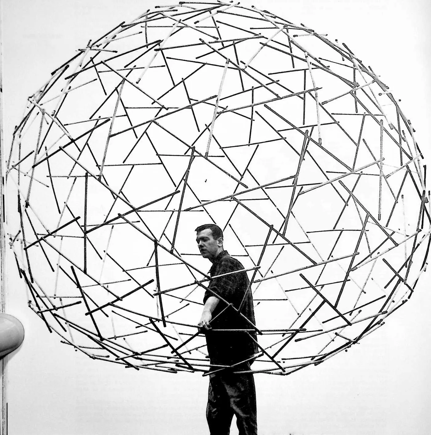
14 OCTET TRUSS (1961)
2U.S. PATENT—2,986,241
APPLICATION—FEBRUARY 7, 1956
SERIAL NO.—563,931
PATENTED—MAY 30, 1961
3 Nature’s simplest structural system in the Universe is the tetrahedron. The regular tetrahedron does not fill all-space by itself. The octahedron and tetrahedron complement one another to fill all-space. Together they produce the simplest, most powerful structural system in Universe.
4 I first used the name octahedron-tetrahedron truss. I then shortened it to the ‘‘octet truss.’’ Having shipped it across state fines, I applied for a trademark for the octet truss.
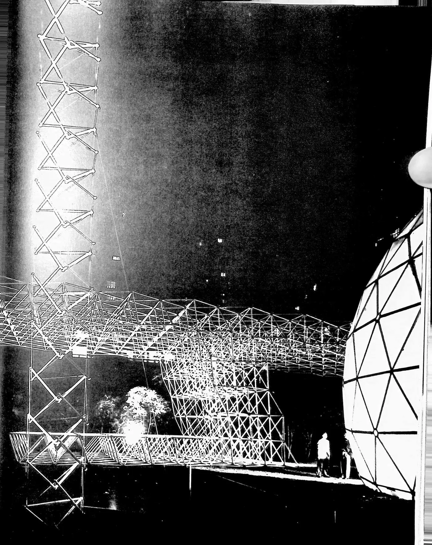
5 It is interesting that at the present time, twenty-two years later, the U.S. government is specifying in its bids for space structures the octet truss (my copyrighted trademark name) for all the main structuring for space stations.
6 UNITED STATES PATENT OFFICE
7 Richard Buckminster Fuller, Forest Hills, N.Y. (407 S. Forest St., Carbondale, III.)
8 SYNERGETIC BUILDING CONSTRUCTION
9 My invention relates to a truss construction for building purposes; particularly to roof, wall and floor framework and to a combined roof and wall framework or wall and floor framework, etc.
10 SUMMARY
11 In my prior patent, No. 2,682,235, issued June 29, 1954, I have disclosed how to gain a surprisingly favorable weight-strength ratio in structures of generally spherical form, now widely known both here and abroad as ‘‘geodesic domes.’’ The present invention is a discovery of how to gain an extremely favorable weight-strength ratio in structures of other forms, including those which are functionally conformed in shape for special purpose applications as well as more conventional forms based on the rectangular prism rather than sphere. In the sphere, the tremendous gain in the ‘‘ratio’’ accrued primarily from a unique arrangement of the main structural elements in which they are all aligned with great circles of a common sphere. In this sense, geodesic construction could be considered inapplicable as such to building frameworks of other than spherical form. However, I have found that if a flat roof, wall or floor framework is built up of struts (or sheets) of equal length (size) in such a fashion that such elements are comprised within a common octahedron-tetrahedron system, the strength of the framework is far greater than would be predictable using any conventional formulae based on resolution of forces and known values of strength of materials. In fact, my practical tests have shown that the actual strength of these ‘‘flat’’ one system octahedron-tetrahedron structures so far exceeds calculated values as to suggest a hypothesis that such structures are ‘‘synergetic’’ in the sense
12 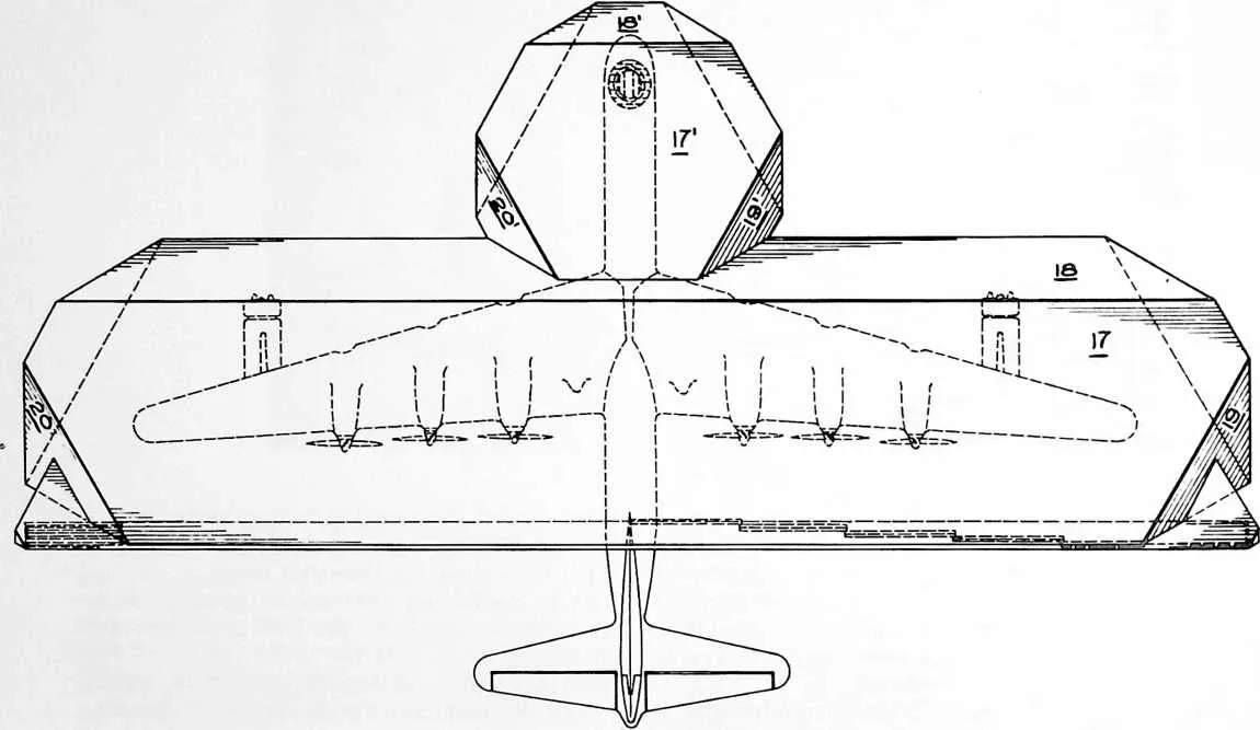 that we have a stress behavior in the system which is unpredicted by its parts.
13 In general, my invention consists of a roof, wall and/or floor framework consisting of a truss in which the main structural elements (e.g. struts or triangular sheet members) form equilateral triangles interconnected in a pattern consisting of octahedrons and tetrahedrons with the major axes of all octahedrons in parallelism throughout the framework. Thus all such structural elements are comprised within a single octahedron-tetrahedron system, and this apparently yields a new optimum of tensile-compressive integrity throughout the framework. Note that the singleness of the octa-tetra system or ‘‘octetruss,’’ carries throughout the roof, wall and floor intersections. This is made possible by a novel alignment of the intersecting truss ‘‘surfaces’’ which holds to the integrity of the strength-creating octa-tetra system. The advantages of my construction are thus obtainable in combined roof-wall, wall-floor, and roof-wall-floor combination frameworks, as well as in individual floor, wall or roof frameworks. Consequently my invention will be found to provide a comprehensive solution to all building truss construction problems, yielding in each application a synergetic and essentially surprising result in terms of the fundamental weight-strength ratio.
15 Definitions of terms
16 Octahedron—A polyhedron having eight equal equilateral triangular plane faces or sides; may be skeletal, as when made of interconnected struts; or continuous, as when made of interlocking or interconnected sheets or plates; or partly skeletal and partly continuous.
17 Tetrahedron—A polyhedron having four equal equilateral triangular plane faces or sides. Like the oc-
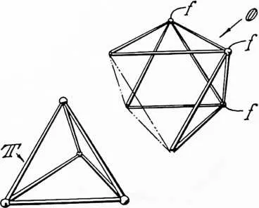
18 Fig. 6 is a schematic view of the octahedron and tetrahedron of Fig. 5 separated for clear illustration.
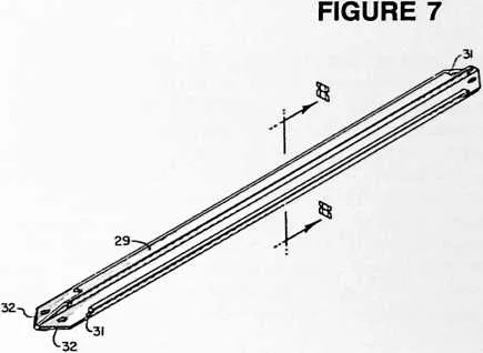
19 Fig. 7 is a detail perspective view of one of the struts of the truss of Figs. 4 and 5.
20 Fig. 8 is an enlarged cross-sectional view on the line 8--8 of Fig. 7.
21 Fig. 9 is an enlarged detail of a representative wall and roof intersection corresponding to the portion shown
22 FIGURE 2
24 tahedron, it may be skeletal, continuous, or a combination of the skeletal and continuous forms.
25 Octahedron-tetrahedron system—An assemblage of octahedrons and tetrahedrons in face to face relationship. Thus when four tetrahedrons are grouped to define a larger tetrahedron, the resulting central space is an octahedron; together, these figures are comprised in a single, or ‘‘common’’ octahedron-tetrahedron system.
26 Framework—The frame of a structure for enclosing space, or the frame of a roof, wall or floor; used to distinguish from individual frame components of a roof, wall or floor, so as to denote the whole as distinguished from its parts.
27 within circle 9 in Fig. 2. This view illustrates how all the plane surfaces of the truss conform to a common octahedron-tetrahedron system so that vector equilibrium is obtained throughout both the walls and roof of the dock framework.
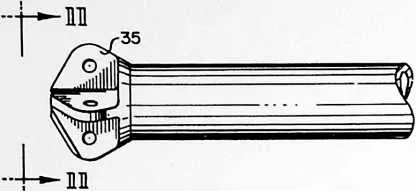
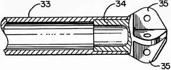
28 Fig. 10 is a side elevational view of a modified form of strut.
29 Fig. 11 is an end view of the strut of Fig. 10.
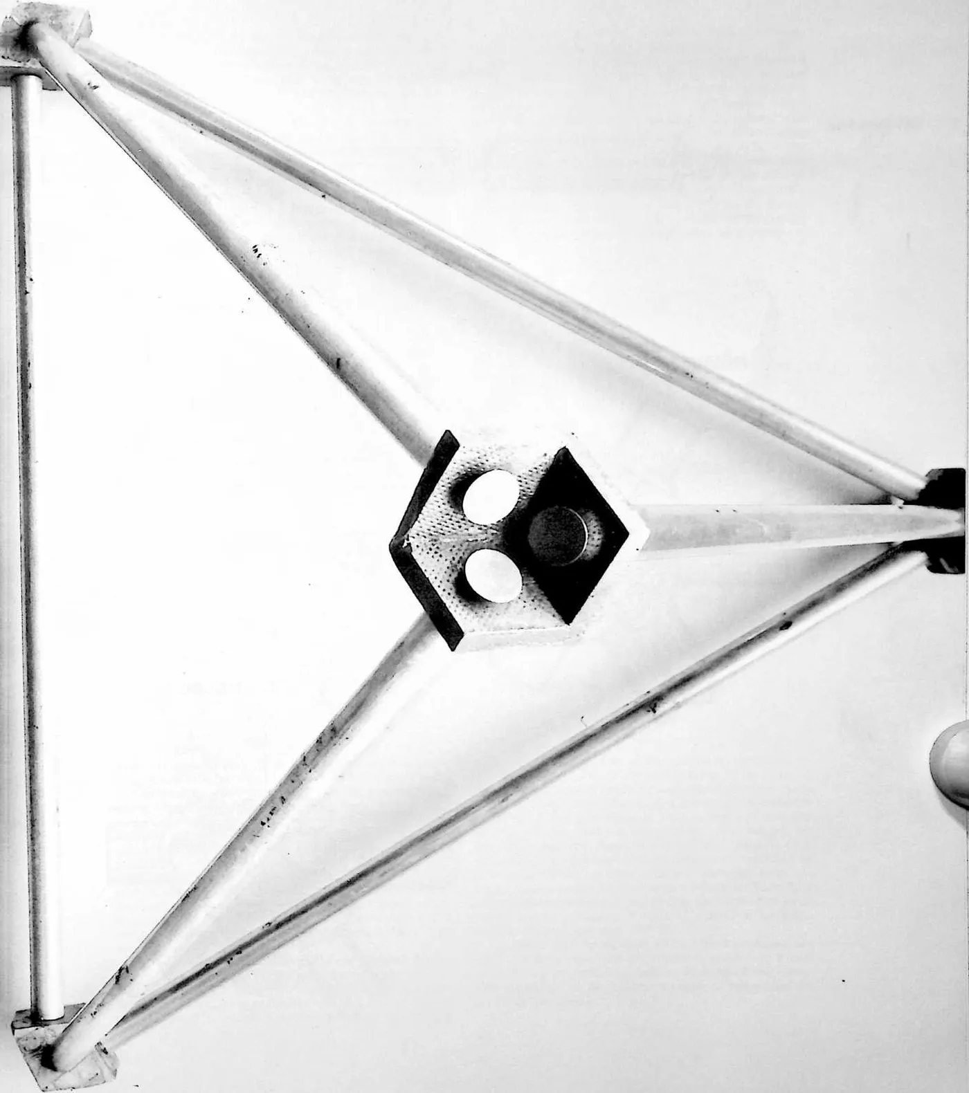
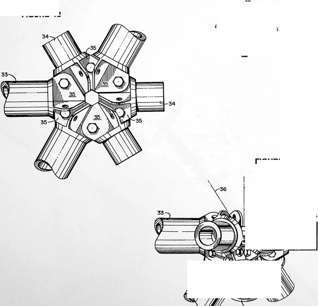
30 Fig. 12 is a plan view of a representative connection.
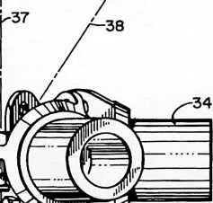
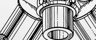
31 Fig. 13 is a side elevational view of the same connection.
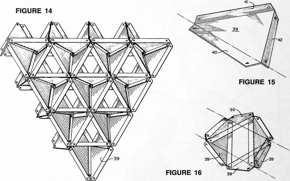
32 Fig. 14 is a top perspective view of a modified form of truss.
34 Synergy—The behavior of a system as a whole unpredicted by its parts.
35 DESCRIPTION
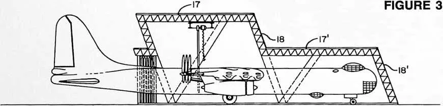
36 Fig. 1 is a plan view of a servicing dock for a B-36 bomber, the roof and walls of the dock being constructed in accordance with my invention.
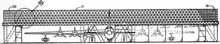
37 Fig. 2 is a front elevational view of the same dock.
38 Fig. 3 is a vertical sectional view through the center of the dock.
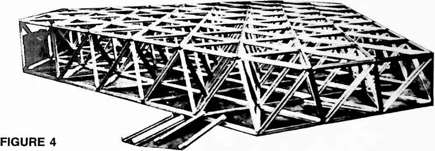
39 Fig. 4 is a perspective view of a representative truss section of the roof and wall framework of the dock or other structural framework.
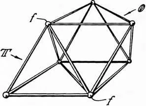
40 Fig. 5 is a perspective view of one of the octahedrons and a conjoined tetrahedron comprised in the truss of Fig. 4.
41 Fig. 15 is a perspective view of one of the sheets or plates which go to make up the truss of Fig. 14.
42 Fig. 16 is a similar perspective view of four such plates assembled to form one of the octahedrons of the truss of Fig. 14.
43 Reference is made first to Figs. 5 and 6 to illustrate definitions given in the Summary. Fig. 5 shows an octahedron O and a conjoined tetrahedron T which may be imagined as being formed of a number of struts of equal length joined together at their ends in any suitable manner, as by fittings f. In Fig. 6 the octahedron and tetrahedron of Fig. 5 are separated for clear illustration of the forms of these two kinds of polyhedrons. Tetrahedron T has six struts and four equal equilateral triangular plane faces or sides. Octahedron O has twelve struts and eight equal equilateral triangular plane faces or sides. In Fig. 6 three of the struts have been shown by dot-dash lines because, when the tetra T and octa O are conjoined as in Fig. 5, these three struts are common to T and O.
44 As the truss is assembled so as to extend or ‘‘grow’’ in other directions, we of course have common struts and common faces or sides between all of the conjoined octas and tetras in the complete framework, and if we adhere to the integrity of this ‘‘Octetruss’’ system, the structure will be characterized by complete vector equilibrium. Also, the major axes of all octahedrons will be in parallelism throughout the framework, whereby all of the structural elements will be comprised in a single octahedron-tetrahedron system of optimum tensile-compression integrity throughout. Further, the sides of the octas and tetras will lie in common planes forming plane surfaces of the truss. The arrangement can additionally be defined as a roof, wall and floor framework consisting of a truss in which the main structural elements form triangles interconnected in a pattern defining four AAA, BBB, CCC and DDD. Thus the points A,A and A together define a first plane, the points, B,B and B a second plane, and so on. A'A'A' is a plane parallel to plane AAA and is therefore not a plane ‘‘unique’’ from plane AAA. So we have in effect a system made up of four unique sets of parallel symmetrically oriented, omnitriangulated, planes, and for simplicity say, merely, four unique planes.
45 Fig. 9 also illustrates the singleness of my octa-tetra system which carries throughout the roof, wall and floor intersections. This is made possible by a novel alignment of the intersecting truss ‘‘surfaces’’ AAA, BBB, etc., which alignment holds to the integrity of the strength-creating octa-tetra system. The advantages of my construction are thus obtainable in a roof-wall combination framework as shown in Fig. 9, and in wall-floor and roofwall-floor combination frameworks, as well as in individual floor, wall or roof frameworks built of trusses such as shown in Fig. 4.
47 unique planes intersecting one another at acute angles, all such planes conforming to a common system of polyhedrons. Each ‘‘unique’’ plane is considered as including planes parallel to it, the point being that there are planes extending in four distinct directions and symmetrically oriented with respect to one another. (In a cube or rectangular prism we would have only three unique planes.) The polyhedrons (octahedrons and tetrahedrons) may be skeletal, as when made of interconnected struts as shown in Figs. 5 and 6; or continuous, as when made of interlocking or interconnected sheets or plates as shown in Figs. 14, 15 and 16 to be described; or partly skeletal and partly continuous, as when made partly of interlocking sheets and partly of struts. Fig. 14 may be imagined as illustrative of a combination of the skeletal and continuous forms in that some of the sides of the polyhedrons are ‘‘open.’’
48 Again referring to Fig. 5, we may now proceed to the definition of the octahedron-tetrahedron system as given in the Summary: an assemblage of octahedrons and tetrahedrons in face-to-face relationship. When four tetrahedrons are grouped to define a larger tetrahedron, the resulting central space is an octahedron; together, these figures are comprised in a single, or ‘‘common’’ octahedron-tetrahedron system.
49 The four unique planes of the system will also be comprehended from Fig. 9 in which they are represented by
50 With these fundamental concepts in mind, it is now possible to comprehend the description of a particular embodiment of my invention made according to the best mode contemplated by me for carrying it out. This embodiment is illustrated in Figs. 1--9 inclusive which disclose how to construct a roof and wall framework for an airplane hangar or servicing dock. Represented is a ‘‘nose dock’’ for a B-36 bomber. The four unique planes of this dock framework are indicated at 17, 18, 19 and 20 (and again at 17', 18', 19' and 20'). In Fig. 1 the dock is considered as roofed and sided, or ‘‘skinned’’—i.e. roofed with corrugated aluminum sheet and having a polyester resin skin over the side walls of the framework. While my invention is applicable to the construction of frameworks, and truss elements therefor, of any desired material, or materials, the particular servicing dock here shown is considered to have a framework built of extruded aluminum struts, roofed with corrugated aluminum and sided with a plastic membrane.
51 In Fig. 2 it may be considered either that the plastic membrane is removed to show the ‘‘surface’’ elements of the framework, or that these surface elements are discernible through the plastic membrane cover. In any case it has been my purpose in Fig. 2 and in the Fig. 3 cross-sectional view, to reveal how it is that the single octahedron-tetrahedron system is carried throughout the roof and the various other plane surfaces of the frame-
54 FIGURE 5
55 ft.2. The construction is entirely of aluminum extrusions with a total strut weight of 74,595 lbs. The corrugated aluminum roof cover weighs 19,892 lbs. and the wall membrane 5,910 lbs. The total weight of the entire structure is 115,887 lbs., but if we subtract the weight of the door and track, the weight of the covered framework itself is just over 100,000 lbs. (100,397).
56 The significance of these figures will be understood when it is realized that the weight of the structure is a mere 0.115 lbs./ft.3; that the foundation load is only 254 lbs. per lineal foot; and that when disassembled the modular parts pack for shipment into approximately /aso of its ultimate cubic enclosure. Actually this entire hangar, including the struts, corrugated aluminum roof, membrane,
58 work. I wish to emphasize that this arrangement is not arbitrary, but rather is based upon my discovery that a system possessing this kind of design integrity yields strikingly improved results in terms of strength and lightness; also in terms of its low packaging cube; i.e., when disassembled, the modular parts pack for shipment into far less space as compared with its ultimate cubic enclosure. Other advantages flow from these, and as applied for example to airplane servicing docks and other military structures, introduce an entirely new concept in logistics. The extreme lightness in turn produces important reduction in foundation loading. The fact that all of the modular elements (struts or sheets as the case may be) are the same, simplifies erection by eliminating selectivity of parts. Any member is the right member and very little skill is required for assembly. The structure is adaptable
60 FIGURE 6
61 for many uses. It can form flat slabs for roof or floor construction. It can be made as a pitched roof, and can be adapted for use as a bridge or trestle for vehicle or pedestrian. Working floors and platforms for hangars and other buildings can be made from the same units as comprise the building structure itself, and can be comprised within the same octa-tetra system, further contributing to the realization of the advantages flowing from the unitary character of my system of construction.
62 In order to give some notion as to the practical advantages of my invention in the particular adaptation selected for illustration, I may cite that the servicing dock for the B-36 bomber is 296' in length by 68' in width, the nose section comprising an area approximately 54' x 56', providing an over-all covered area of 19,692 doors and tracks when packaged for shipment, can be carried by two trailer trucks with space to spare in the second truck. This is on the basis of a trailer truck of a capacity of 1536 cubic feet. The strength of the framework exceeds manyfold the results which would be calculated using any conventional engineering formulae based on revolution of forces and known values of strength of materials. This suggests that there is some kind of a stress behavior in the system as a whole which cannot be predicted, and which perhaps can only be described as ‘‘synergetic.’’
63 Note in Fig. 3 that the struts of the roof are in alignment with the struts in the walls so that we adhere to the common octahedron-tetrahedron system, producing a framework of novel integrality. In the specification and in the claims I employ the term ‘‘framework’’ in the sense defined in the Summary, as the frame of a structure for enclosing space, or the frame of a roof, wall or floor; distinguishing from individual frame components of a roof, wall or floor so as to denote the whole as distinguished from its parts. Fig. 9 further illustrates the detail of the system in which the major axes of all of the tetrahedrons are parallel throughout the framework, or in which all of the main structural elements (struts) form triangles interconnected in a pattern defining the four unique planes AAA, BBB, CCC and DDD intersecting one another at acute angles, all such planes conforming to the common system of polyhedrons.
64 In Fig. 4 we see in perspective a representative truss section of the roof and wall framework of the dock of Figs. 1--3. And in Fig. 5 we see one of the octahedrons O and one of the tetrahedrons T comprised in the truss of Fig. 4 (compare the exploded view, Fig. 6).
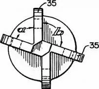
65 The struts may be of any desired form, but in Figs. 7 and 8 I have illustrated a feature of a preferred construction in which the struts are generally X shape in
66 
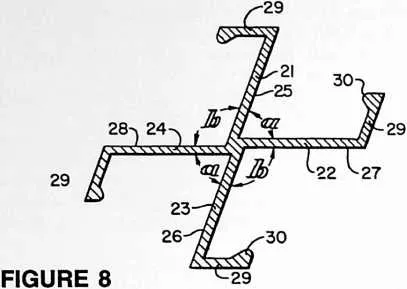 cross section, with the sides 21--24 of the X section of the struts disposed at such an
angle to one another as to lie substantially in the planes of the sides of the octahedrons and
tetrahedrons constituted by the respective struts. (Angles a approximately 70° 32', angles b
approximately 109° 28'.) Further, as seen best in Fig. 8, the sides of the X section of the struts
are offset sufficiently to bring one surface of each into the plane of the center of the X. Otherwise
stated, surface 25 of side 21 lies in the same plane as surface 26 of side 23. Similarly, surface 27 of
side 22 lies in the same plane as surface 28 of side 24. The respective sides 21--24 may be
provided with strengthening or stiffening flanges 29 swastika fashion, and the flanges may have
inwardly extending projections 30 of bead-like conformation. I have had struts of this form
fabricated successfully as aluminum alloy extrusions. They may, if desired, be extruded of
magnesium or other alloys, or other materials. Flanges 29 should be cut away as shown
at 31 in Fig. 7 at each end of the strut so as to avoid interference with the sides of
interconnected struts where they are joined together. Also, the ends of the struts are cut
back at an angle, as at 32, for the same purpose, and holes are drilled for bolts or
rivets.
cross section, with the sides 21--24 of the X section of the struts disposed at such an
angle to one another as to lie substantially in the planes of the sides of the octahedrons and
tetrahedrons constituted by the respective struts. (Angles a approximately 70° 32', angles b
approximately 109° 28'.) Further, as seen best in Fig. 8, the sides of the X section of the struts
are offset sufficiently to bring one surface of each into the plane of the center of the X. Otherwise
stated, surface 25 of side 21 lies in the same plane as surface 26 of side 23. Similarly, surface 27 of
side 22 lies in the same plane as surface 28 of side 24. The respective sides 21--24 may be
provided with strengthening or stiffening flanges 29 swastika fashion, and the flanges may have
inwardly extending projections 30 of bead-like conformation. I have had struts of this form
fabricated successfully as aluminum alloy extrusions. They may, if desired, be extruded of
magnesium or other alloys, or other materials. Flanges 29 should be cut away as shown
at 31 in Fig. 7 at each end of the strut so as to avoid interference with the sides of
interconnected struts where they are joined together. Also, the ends of the struts are cut
back at an angle, as at 32, for the same purpose, and holes are drilled for bolts or
rivets.
67 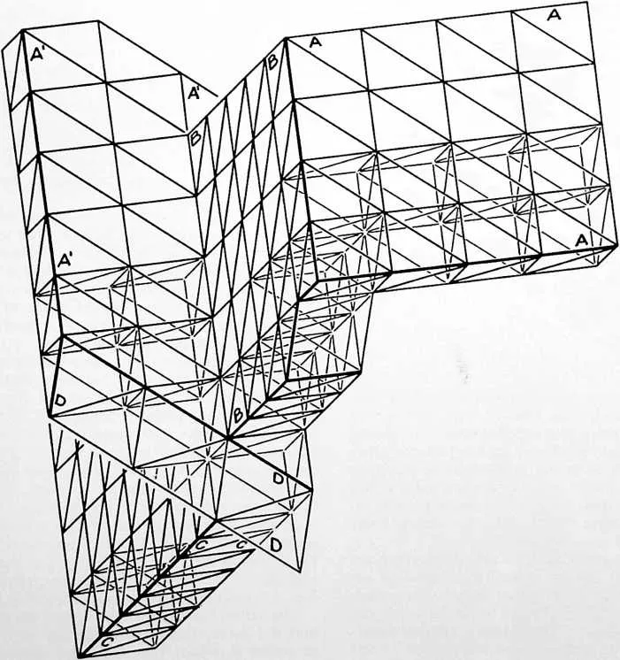 Another form of strut according to my invention, comprises aluminum tubing or the like,
into the ends of which are inserted fittings so designed that the ends of the struts will be
generally X shape in cross section. This modification is illustrated in Figs. 10 and 11, which may
for example comprise an aluminum tube 33 to the ends of which are fastened the fittings which
have tubular portions 34 to match the inside tube end, and flanges 35 disposed in the
same manner as the sides 21--24 of the X section described with reference to Figs. 7
and 8. These fittings are drilled to receive the fastenings used to secure the various
struts together at the intersections. (These are the fittings /previously referred to
in describing Figs. 5 and 6.) They go together in the manner illustrated in Figs. 12
and 13, Fig. 12 being a plan view of a representative connection, and Fig. 13 a side
elevational view of the same connection. This is a ‘‘9-point’’ connection providing six
struts (six axii) radiating outwardly from the center of one of the hexagons that can
be seen in the plane A'A'A' of Fig. 9, and three struts extending downwardly from
that
Another form of strut according to my invention, comprises aluminum tubing or the like,
into the ends of which are inserted fittings so designed that the ends of the struts will be
generally X shape in cross section. This modification is illustrated in Figs. 10 and 11, which may
for example comprise an aluminum tube 33 to the ends of which are fastened the fittings which
have tubular portions 34 to match the inside tube end, and flanges 35 disposed in the
same manner as the sides 21--24 of the X section described with reference to Figs. 7
and 8. These fittings are drilled to receive the fastenings used to secure the various
struts together at the intersections. (These are the fittings /previously referred to
in describing Figs. 5 and 6.) They go together in the manner illustrated in Figs. 12
and 13, Fig. 12 being a plan view of a representative connection, and Fig. 13 a side
elevational view of the same connection. This is a ‘‘9-point’’ connection providing six
struts (six axii) radiating outwardly from the center of one of the hexagons that can
be seen in the plane A'A'A' of Fig. 9, and three struts extending downwardly from
that
68 FIGURE 9
70 FIGURE 12
71 FIGURE 11
72 FIGURE 13
74 center as the apex of the tetrahedron directly below it.
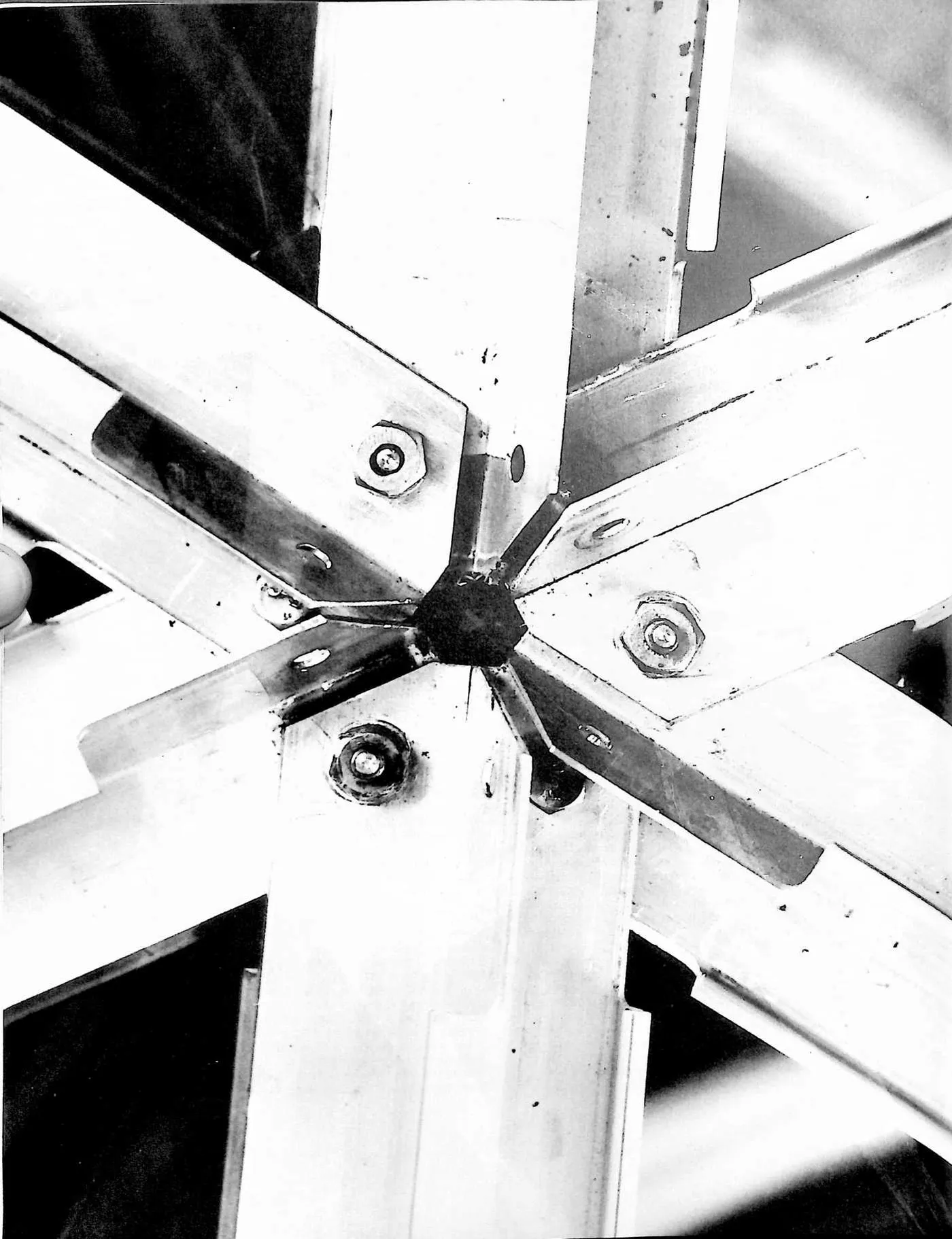
75 In sections of the framework where we get in effect a double truss, as occurs whenever we come to a roof-wall or wall-floor intersection, there is required a full ‘‘12- point’’ (six axii) intersection, and the construction illustrated in Figs. 12 and 13 is adapted for such an intersection, the three additional struts coming into the intersection on the axes 36, 37 and 38 shown in Fig. 13. Note in Fig. 12 that flanges 35 of the fittings overlap in a uniform clockwise pattern. However, these fittings may if desired be designed for counter-clockwise overlapping. In either case the connection is characterized by what I term ‘‘plus and minus turbining.’’ Inasmuch as two members can never go through the same point, they must always turbine right or left—as in the poles of a tepee. I believe the the particular construction which I have described one another at acute angles, in which all such planes conform to a common system of polyhedrons.
76 Figs. 14 through 16 illustrate a typical application of my invention to frameworks as built up of sheet modules instead of strut modules. Fig. 15 shows the module. It may, for example, be a thin sheet 39 of aluminum with a flange 40 extending from one edge thereof coplanar with the body of the sheet and flanges 41 and 42 extending from its other two edges at the proper angle to lie in the planes of the faces of the octahedrons and tetrahedrons of the system of the framework. Flange 41 extends upwardly and outwardly of the sheet, flange 42 downwardly and outwardly. The flanges may be apertured for fastenings as shown, but in some cases I prefer that the flanges of the aluminum sheets be held together with epoxy cement.
78 with reference to Figs. 12 and 13, as well as the connections made with the struts in Figs. 7 and 8, possess peculiar advantages when employed as the connecting points of the four unique planes of my framework, and that this so-called ‘‘turbining’’ construction contributes importantly to the surprising results which I have been able to attain with such frameworks. However, I have found it possible to obtain exceptional results also with other types of connections, so that the octa-tetra construction may be considered to have utility apart from the particular construction described, while in another aspect of my invention the connection and the octa-tetraconstruction are considered to possess a special co-action when both are employed together.
79 In some cases the surface aspect of my framework may present the plane which represents the middle of the octahedrons. In such a case we have an example of a one-half octahedron, or pentahedron. Such a system retains the feature of providing four unique planes intersecting
80 In Fig. 16 we see four of the aluminum sheets 39 assembled to form one of the octahedrons of the truss of Fig. 14. This truss is made up entirely of identical modules, just as the strut form of truss previously described is made up of identical modules. That is, one type and size of strut, or one type and size of sheet, does the job for the entire structure, floors, walls, and roof. Thus, in each case, I build a roof, wall or floor framework consisting of a truss in which the main structural elements form triangles interconnected in the pattern which has been fully described hereinabove. Sheet 39 is in the form of an equilateral triangle. Flanges 41 and 42 extend at an angle thereto of approximately 109° 28'.
81 The terms and descriptions which I have employed are used in a descriptive and not a limiting sense, and I have no intention of excluding such equivalents of the invention described, or of portions thereof, as fall within the scope of the claims.