
22 ROWING NEEDLES (WATERCRAFT) (1970)
2U.S. PATENT—3,524,422
3 PATENTED—AUGUST 18, 1970
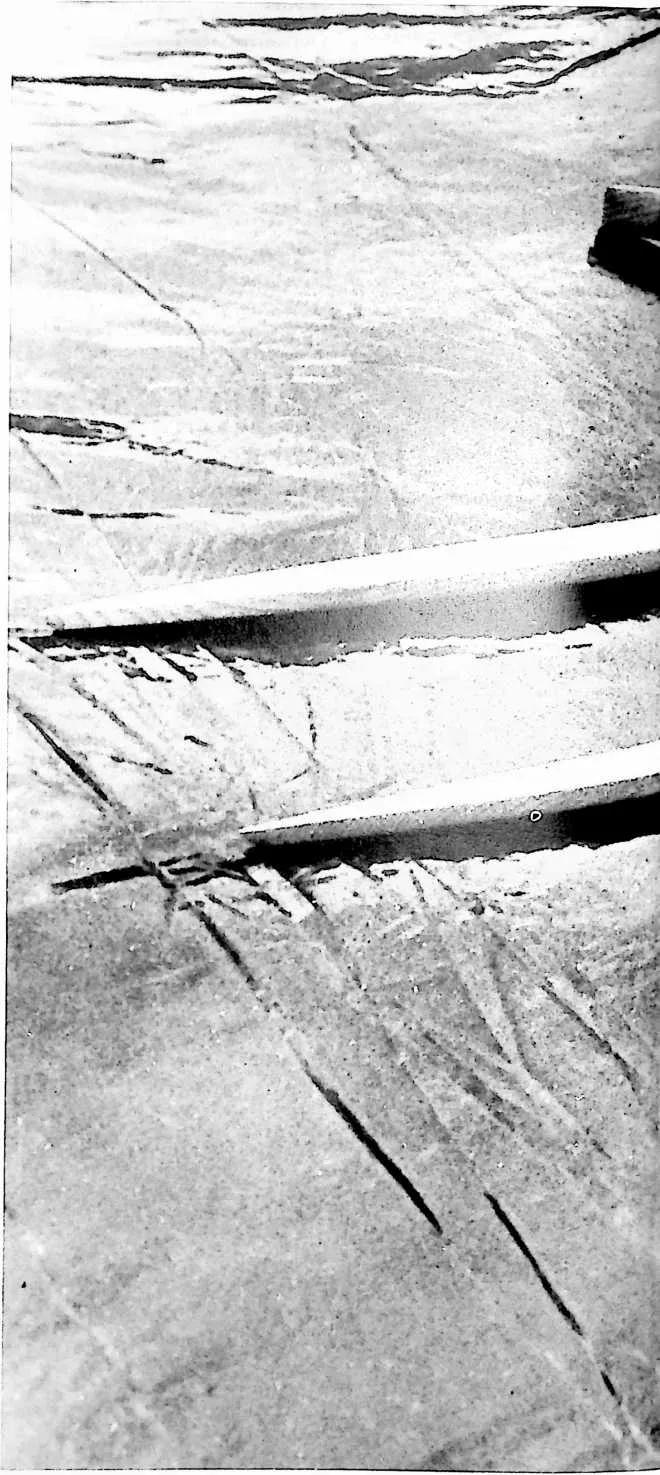
4 FIGURE 1
6 I am an oarsman; I’ve found in all my life nothing that employed my total muscles more effectively and put me into such a healthy condition as rowing in a sliding seat outrigger, what is called a ‘‘single’’ shell. These single shells average around twenty-two feet in length, and have a beam of only eighteen inches. They are kept balanced entirely by the oarsman, and his oars are passed rigidly through oarlocks and outriggers. I’ve done much such rowing.
7 On one occasion, I was rowing in Wiscasset, Maine, using a ‘‘single’’ that was loaned to me by my friend Charles Chase. I rowed what is called ‘‘upriver,’’ which is from the float in Wiscasset. This is about two miles to the windward of the Wiscasset anchorage and dock, when my right steel oarlock broke (it had apparently been rusting), and immediately, instinctively to keep myself balanced, my lefthand oar became more and more vertical, which tended to push more and more of the bulk of the wooden oar to greater and greater depth. I suddenly found myself sitting using just the buoyancy of that one oar to self-balance against completely rotating. My boat was pouring in water. Then I realized that I was holding on to the oar whose oarlock had broken. I realized that I could gradually rotate that broken oarlock oar out along the outrigger. The more I brought out along the outrigger, the more my left-hand oar was able to emerge. Finally, I was able to get the broken oarlock with its woodenness impinged on the sharp vertical breakage point of the oarlock itself. Now my two oars were out horizontally again, but I obviously could not row with a broken-oarlocked oar. I could row with the left-hand oar. I figured out with the wind blowing me back toward the float at the Wiscasset anchorage, that I might be able to steer myself downwind by from time to time rowing myself doing such rowing there, one has to avoid several things. There are very large boats and oar ships coming down from Lake Superior to bring steel to the various mills of Ohio and Michigan. They usually keep on the eastern shores of Belle Isle, and I would row on the western side of Belle Isle between the city of -troit, on the Detroit boat club on Belle Isle. The waters from Lake Sinclair to the north of Belle Isle come down by Belle Isle on both sides, and by the city of Detroit, and gradually out to Lake Erie. There is quite a current, then, that runs by Belle Isle. Rowing in a ‘‘single’’ out of the Detroit Boat Club on Belle Isle, I would go northward to Lake Sinclair. In
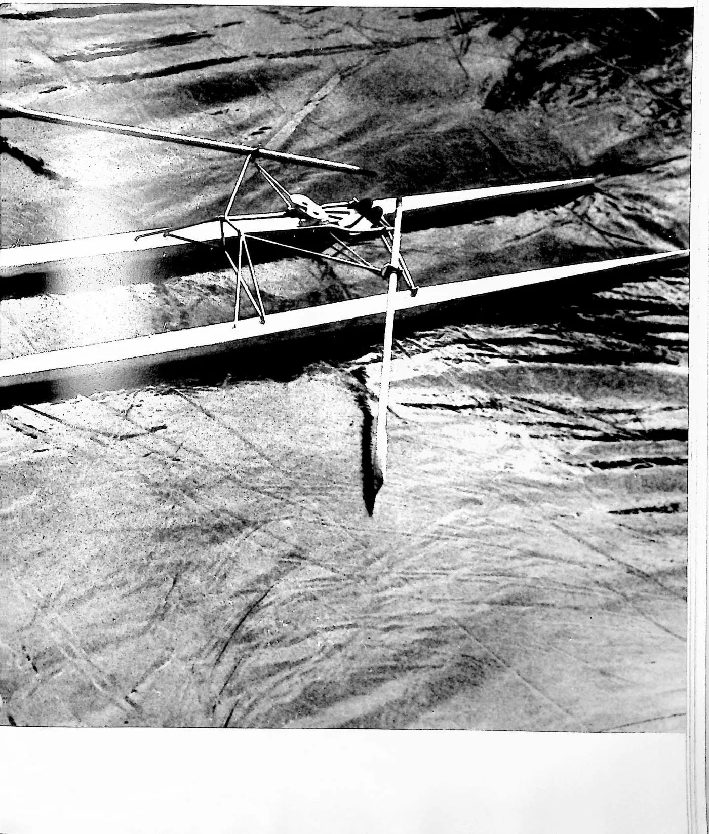
8 FIGURE 2
10 FIGURE 3

12 in a circle, and then coming off on the right part of that circle directly to windward of the float. I did succeed in getting home, in getting my ‘‘single’’ out of the float and stored away. The water that day was about 58° F. If I had rolled over, that coldness would probably have done me in before I would have been able to swim home.
13 On another occasion, I was rowing in DeDetroit and the island. Once we got into Lake Sinclair it was easy to stay clear of other boats. I was coming back to Belle Isle from Lake Sinclair when suddenly what was called a ‘‘gold cup power boat,’’ a racing boat, went very thoughtlessly so close to me that its enormous wave rolled my shell over.
14 I was now in the water, and the oars were locked into the oarlocks on the outriggers, and
16 I could take hold of the boat and swim with my legs pushing it. I felt it was very touch and go whether I could get in close enough to Belle Isle to get up on the beach before I was swept down through the city of Detroit and out toward Lake Erie. Luckily, I did get it over to the shore of Belle Isle, and I was then able, standing in the shoal water, to remove the oars from the outriggers, to pick the shell up and dump the water out of it, to re-rig the oars, to mount back into my sliding seat, and to bring the shell back to the Detroit Boat Club, to whom the ‘‘single’’ belonged.
17 Because, then, I had found on two occasions how dangerous a ‘‘single’’ really can be, because I cared so much about rowing, I saw I could make a catamaran by putting two ‘‘singles’’ together, which would prevent the ‘‘singles’’ from being rolled over, and if my two shells were absolutely watertight, what I call needles, then it could not be foundered in any way.
18 It will probably be very important in years to come for people to be able to have a rowing machine like this to put on top of their cartops and be able to take to appropriate areas to row. If you have what is called a rowing ma-
21 chine inside your house, and you start to really work it, you’ll find you’ll breathe more powerfully, and if there’s lots of dust in the house, you’ll find you’ll really feel and taste that dust badly. There is nothing quite so pure as the air inventions we 8et when rowing a ‘‘single’’ on a remote
22 260 lake or river, and I want to be able to get out
23 where the waves are large, so I developed what was then called rowing needles. They are now quite successful, and they have a beautiful hull. They may become popular.
24 UNITED STATES
25 PATENT OFFICE
26 WATERCRAFT
27 This invention relates to watercraft having pairs of floats and especially to an arrangement for maintaining the floats in desired space relation.
28 In the prior art, catamarans and similar type craft have been known, but they are unwieldy and do not have the necessary characteristics for use for various purposes. It is also desirable to be able to control directionally the floating units of such a vehicle so as to either cause them to stay in parallelism for streamlining purposes or to be able to change the angle for blocking or braking. Also, there has not been a satisfactory arrangement for connecting a plurality of units wherein there is sufficient flexibility so that the structure is in effect articulated.
29 One of the objects of the invention is to provide an improved multi-hull watercraft which will maintain the desired relationship of the hulls or float members.
30 Another of the objects of the invention is to provide a watercraft which can be adapted for various uses.
31 Another of the objects of the invention is to provide an efficacious manner of making an articulated watercraft.
32 In one aspect of the invention, at least a pair of floating members or hulls are used which are kept in a substantially parallel arrangement by transverse structural members longitudinally spaced from each other, one toward the bow and one toward the stern. The transverse structural members are arranged so that forces involved in keeping the floats aligned are directed from a zone or point on a post vertically over each of the floating elements toward the top of the transversely located vertical post on the other float. The structural members can be formed in several manners. In one arrangement, there can be a cross bar connecting the top of the posts. In another form, a pair of crossed elements can be used extending from the top of one of the posts to the float portion. Also, various shaped members can be used to connect the two posts. The critical consideration is that these elements may have both torsional effect and column effect in maintaining the floats in desired relationship. The positioning of the floats is accomplished by the described arrangement of the vertical posts or vertical portions so that, as the floats twist or take angular relationships other than horizontal in adjusting to the water, the floats will be maintained in their parallel longitudinal axis relative to each other.
33 The arrangement can be used for various purposes. For
36 example, track and sliding seat means, similar to those used in a rowing shell, can be placed thereon with the oars and outriggers fastened to a platform arrangement connected between the vertical posts or the floats.
37 Also, sailboat rigging and gear can be placed on the float member combination with the mast arranged to be pivoted and having a keel at the lower end thereof so that it will always remain vertical. Further, hydrofoil arrangements can be placed at either end of the craft between the two float members.
38 In a still further aspect, a plurality of units can be connected longitudinally with a flexible connection means between float units so that the float members will in effect be articulated.
39 These and other objects, features and advantages of the invention will become apparent from the following description and drawings which are merely exemplary.
40 In the drawings:
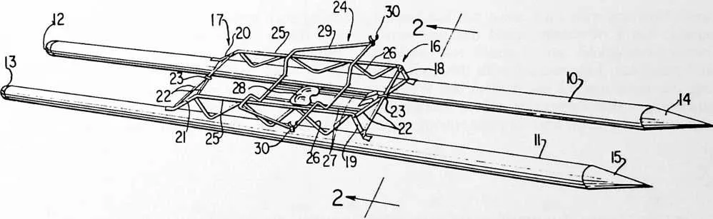
41 Fig. 1 is a perspective view of one form of use of the invention;
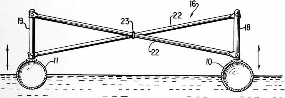
42 Fig. 2 is an enlarged view taken along the line 2--2 of Fig. 1;
43 Fig. 3 is a view of the invention wherein a plurality of units are joined;
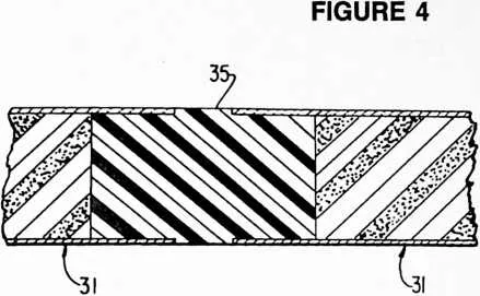
44 Fig. 4 is an enlarged fragmentary sectional view showing one form of connection for use in Fig. 3;
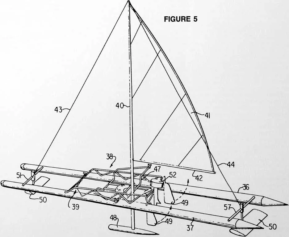
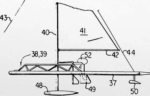
45 Fig. 5 is a perspective view of the invention when used as a sailing craft;
46 Fig. 6 is a fragmentary sectional view of Fig. 5 showing one form of mast arrangement;
47 Fig. 7 is a reduced size fragmentary side view of Fig. 5; and
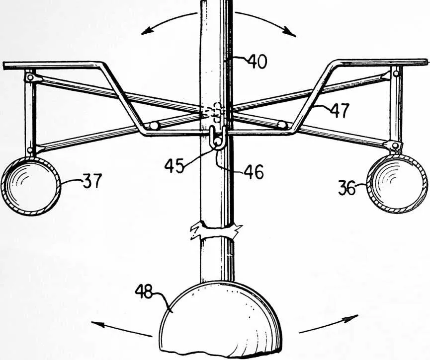
48 Fig. 8 is a sectional view of another form of structural cross member.
49 The invention will first be described in conjunction with a watercraft for rowing use as seen in Figs. 1 and 2. Where appropriate, similar numerals will be given like parts in the various figures. Float members 10, 11 may be of a suitable material such as aluminum tubing. They may
50 FIGURE 7
53 be hollow or may have a foam plastic therein. The leading or bow end of each has rounded heads or plugs 12,13 and conically shaped trailing plugs 14, 15. The heads and plugs can be given contours to provide the best hydrodynamic effects.
54 In the form shown in Figs. 1 and 2, the floats 10,11 are maintained in their desirable substantially parallel relationship by transverse longitudinally spaced structures 16, 17. Vertical posts or members 18, 19, 20, 21 are in spaced pairs and project upwardly from respective floats upon which they are mounted.
55 From the tops of each post there are cross members 22 extending to the lower part of the opposite post. Preferably a loose link 23 encircles the cross members 22 adjacent the crossing point thereof.
56 The rowing or shell assembly 24 is carried by side bars 25 which can have truss arrangement 26 therealong. Tracks 27 support sliding seat 28. Outriggers 29 are also carried by the shell assembly, the outriggers having the usual rowlocks 30 mounted thereon.
57 As the floats tend to follow wave motion, the twisting and movement thereof will be inhibited by compressional and torsional forces exerted on cross members 22 through vertical bars or posts 18.
58 In another form, a plurality of units 31 may be joined with bow unit 32 and a stem unit 33. The stern unit 33 may have a coxswain seat assembly 34 thereon. The bow and stern units have heads and stern plugs similar to that described for Figs. 1 and 2. The ends of the floats of units 31 can be joined by flexible connectors 35 which can be made of any suitable flexible material. The connector also could be made of a tube.
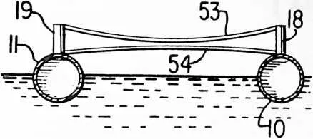
59 As can be seen in Figs. 3 and 4, a form similar to a rowing shell arrangement is the result. The flexible connectors give an articulated effect so the watercraft can follow movement of the water. As is known, the stiffness of a long narrow wooden boat, such as a rowing shell, makes it difficult to operate in rough water. The connector can be made of neoprene, nylon, polypropylene and the like.
60 In a still further form, the float members of the hull can be used to carry a sailing rig such as shown in Figs. 5, 6 and 7. The floats 36, 37 thereof have spaced transverse structural members 38, 39 similar to those previously described. Mast 40 can carry sail 41 and boom 42 in the usual manner. Fore and aft stays 43, 44 can support the mast in a fore and aft direction. The mast is pivotally mounted by pin 45 and yoke 46 to a crossbar 47. Keel or weight 48 at the bottom of the mast 40 will tend to urge the mast to a vertical direction and yet will allow movement thereof in response to wind pressure on the sails. Rudders 49 can be mounted on the assembly. The transverse structural members 38, 39 will permit movement of the parallel floats in a vertical plane because of water movement.
61 As a further arrangement, hydrofoils 50, 50 can be mounted on cross bars 51 as seen in Figs. 5 and 7. The hydrofoil shaft can be raisable and lowerable as needed. Also, an outboard motor 52 could be attached to suitable brackets on the assembly.
62 The transverse structural member can take various forms. For example, as shown in Fig. 8, floats 10, 11 could have the vertical posts or members 18, 19 joined by curved tubing means or struts 53, 54. Also, a single bent member (not shown) rising vertically from each float and then extending across could be used. It also is conceivable that one of the transverse members could be adjustable in water so as to apply a braking force by changing the parallelism of the floats.
63 It should be apparent that details in construction and arrangement of parts could be made without departing from the spirit of the invention except as defined in the appended claims.