
11 PAPERBOARD DOME (1959)
2U.S. PATENT—2,881,717
APPLICATION—JANUARY 24, 1955
SERIAL NO.—483,619
PATENTED—APRIL 14, 1959
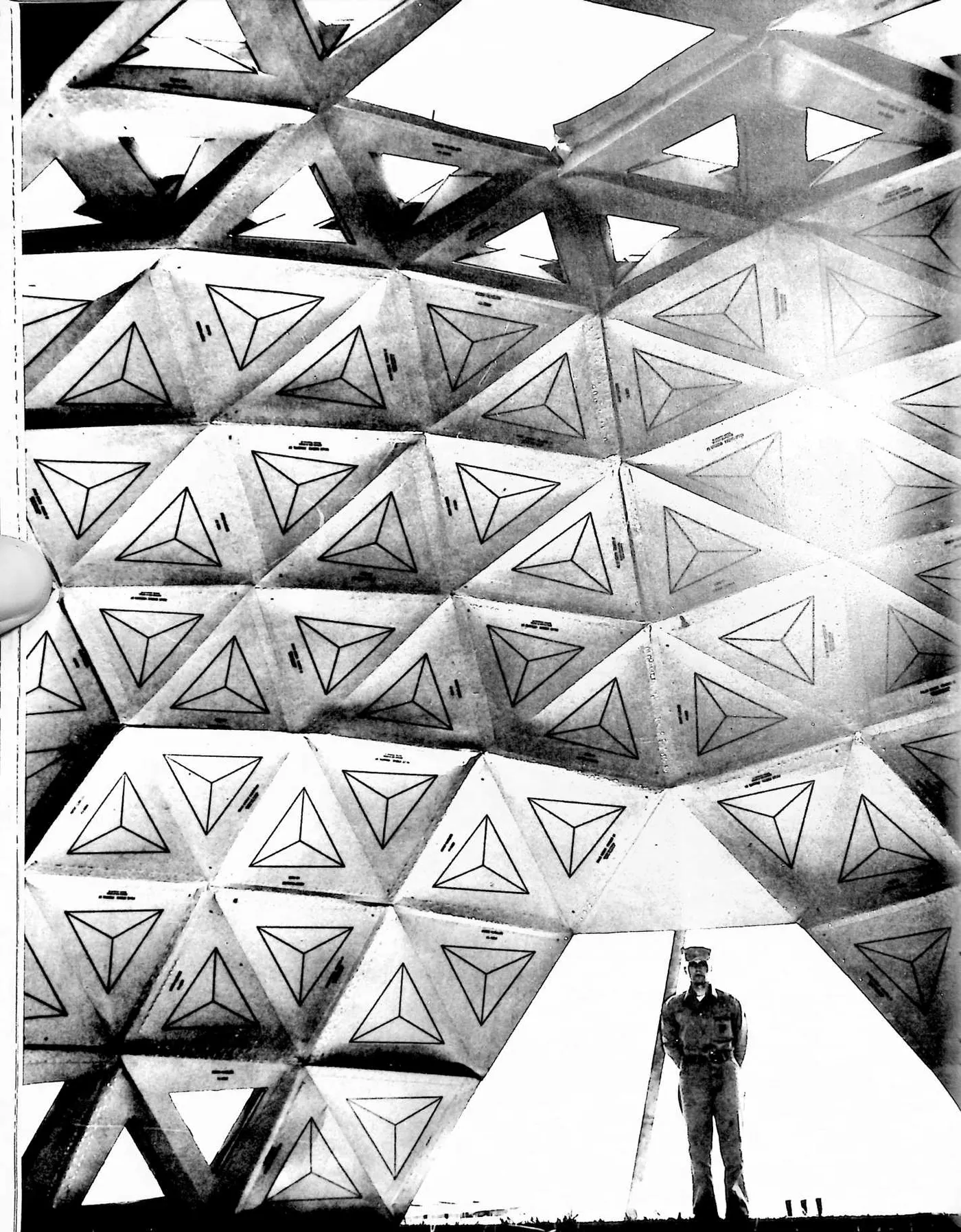
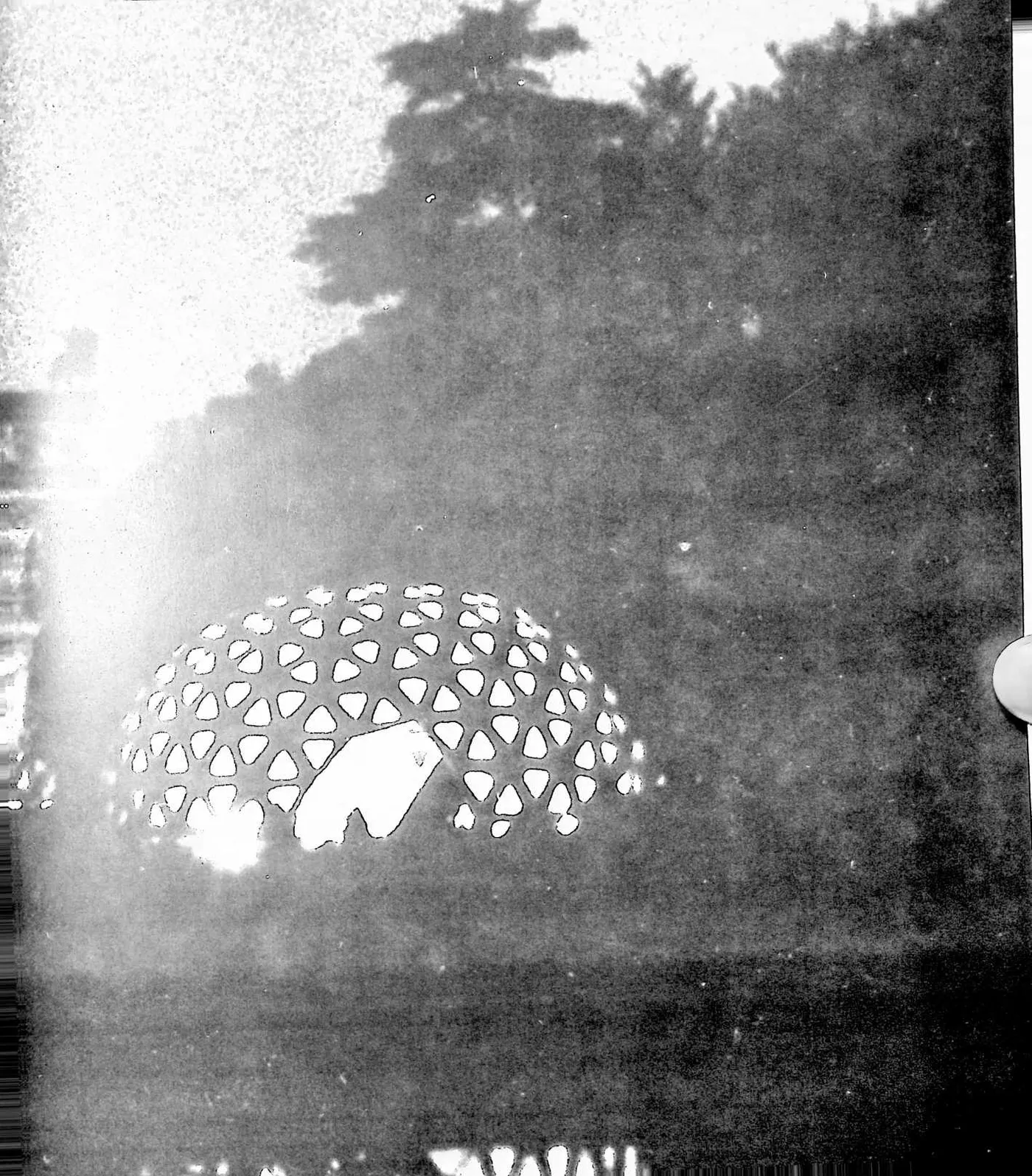
3 Because of the triangulation of the geodesic dome, double-fluted corrugated paperboard proved to be particularly suitable for producing geodesic domes of thirty feet and under. Double-fluted corrugated paperboard is made passing through rollers, and because of this, the rollers can print the folding patterns for the paperboard dome. There’s no way in which man can mass-produce so rapidly as with the printing press. The corrugated paperboard domes are produced at many universities, having first started with Yale University in 1951. They have to be covered with waterproof material, as the paperboard itself is hydroscopic. At the Massachusetts Institute of Technology, I worked with paperboard domes with the Forest Products laboratories and in Wisconsin with the Paper Industry Research Laboratories. We found it would be possible to introduce a compression-providing chemistry at the ‘‘beater’’ stage of the paper manufacturing. The corrugated paperboard used by the armed forces in World War II had an extremely high wet tensile strength, so that cartons could be dropped off on beaches, become very greatly wettened, and not lose their tensile coherence. What they did not have was high wet compression strength. Because they were bound together with steel straps and so forth, the lack of compression stiffness was irrelevant. It is, however, of complete relevance in producing dome structures.
4 The big paper-manufacturing factories had so much business that they could not afford to stop any of their projects and introduce the stiffening agent at the beater stage, so we’ve had to postpone that through the years. However, the high tensile strength of the paperboard made it extremely suitable for dome building, particularly when we have inwardly-turned great circle planes planted surrounding the triangles.
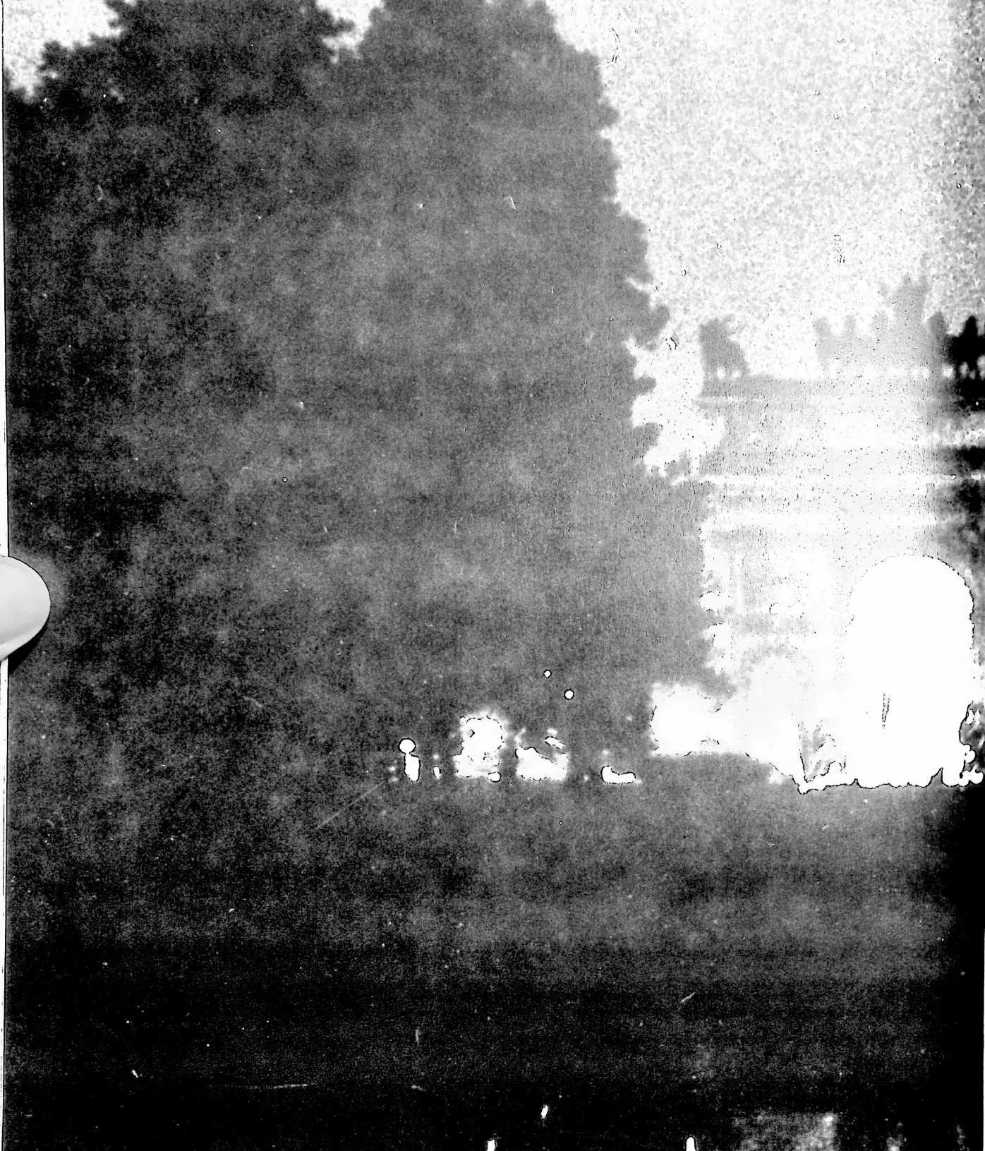
5 Many paperboard domes were built; one of the most notable was done by a New York City Lower East Side gang who covered a twenty-foot-diameter dome with polyethylene sheets of very low cost, and then with aluminum foil, and then with a complete enclosure of half-inch-mesh chicken wire. Then they started cementing the dome outside, troweling the cement onto the chicken wire mesh, and went progressively around the dome with fast-setting cement. However, they waited until the second day before they began to trowel in the higher ranges of the dome, and finally on the third day, they were able to cement in the top, which gave them a very extraordinary fireproof structure, beautifully insulated on the inside, with a complete moisture barrier, and the aluminum foil acted as a radiation barrier reflecting away the unwanted Sun heat in the summer, and retaining the generated heat inside in the winter.
7 UNITED STATES PATENT OFFICE
8 Richard Buckminster Fuller, Forest Hills, N.Y.
9 BUILDING CONSTRUCTION
10 My invention relates to a framework for enclosing space, and to building construction members for use in such a framework and for other uses.
11 SUMMARY
12 Frameworks used in buildings, and for roofs and shelters of all kinds, commonly are constructed of steel, aluminum, wood and the like, and the design of such frameworks is based upon long familiar principles in which relatively heavy compression members are employed in columns, beams and girders. Because of columnar, or compression, loading of such members, they must in general be heavy and stiff to resist buckling under compression. As a result, the ratio of weight to strength is high. In times past, efforts to gain a more favorable weight-strength ratio have brought about the development of the I-beam and the lattice girder; and in more recent times the continuance of such efforts has led to the development of light metals and their strong alloys for use in place of steel where cost does not preclude availing of such lighter weight but more expensive substitutes. Apparently those concerned with the development of frameworks for building construction have not perceived any practicable means to eliminate the use of materials and columnar forms which have high compressive strength. However, I have discovered how to make a building construction member which possesses design characteristics such that the compressive strength of component portions thereof is of relatively small, and perhaps almost negligible, concern. It has been a primary object of my invention to achieve such design characteristics in a general purpose building construction member.
13 I have found further that, by following the design features disclosed herein, it becomes thoroughly practicable to construct building frames of paperboard and the like. So, in popular phraseology, one might say that I have discovered how to make ‘‘cardboard’’ building members and frames—members possessing such surprising strength characteristics as to permit the use of cardboard in lieu of wood, aluminum, steel or other materials which, according to normal concepts of strength of materials, are not at all to be associated with such flimsy stuff as cardboard.
14 According to my invention there is provided a building construction member in the form of a polygonal frame, such as a triangle, having hollow sides perferably triangular in cross-section and centrally reinforced. This member is formed from a single flat piece of paperboard or the like comprising a series of elongated panels arranged end to end with transverse fold lines between the panels, and lateral extensions adjoining the panels along longitudinal fold lines and including fold lines spaced from and substantially parallel to the longitudinal fold lines. The lateral extensions fold about both the longitudinal and parallel fold lines to form a hollow box-like structure which in turn folds about the transverse fold lines between the panels to bring the outer ends of the structure together to form the triangular, or other polygonal, frame.
15 The ends of the lateral extensions are formed with flaps infolding along diagonal lines to form abutting mitered surfaces at the ends of the hollow sides of the polygonal frame. An important feature of my construction resides in gauging the angle of these diagonal fold lines to the number of sides of the polygon to ‘‘crowd’’ the folded lateral extensions within the perimeter formed by the interconnected panels, and set up the mitered joints of the polygon under a degree of pressure for increasing the unitary strength of the frame as set up for use. The elongated panels forming the perimeter of the frame may thus be placed under a degree of tension, tending toward a uniform distribution of stresses throughout the frame, with utilization to a marked extent of the tensile strength of the paperboard in what may be regarded as a skin-stressed frame member.
16 For further maximum realization of tensile properties as well as the compressive strength of the box-form frame portions, at least the outer surfaces of the polygonal frame are coated with a thin plastic film of high tensile strength, such as a vinyl resin which can be brushed, sprayed or otherwise applied to the completed frame members, or which can be applied to one or both sides of the paperboard from which the blanks for the frame members are cut. Extrusion coating can be used to apply the plastic reinforcement to the paperboard sheets, or the paperboard can be impregnated with the plastic. I have found, for example, that a triangular frame member formed in accordance with my invention, when brush painted with a thin film of vinyl plastic acquires astonishing strength characteristics. Thus, such a frame member having nearly equal sides averaging about 19.4 inches in length, the cross-section of the sides being of hollow triangular form with a base width of about 5 inches, and an altitude of about 1.5 inches, is of such strength that when placed with one side of the triangle on the floor it is possible for a 200 pound man to step up on the opposite point of the triangle and place his full weight on it without the slightest visible evidence of distortion or buckling of any of the sides of the frame member. The paperboard used may consist of the ordinary kraft board used in standard forms of shipping containers, and known as corrugated fibreboard. In the example just given, I employed a double-faced sheet in which the smooth outer sheets, known in the paperboard box business as ‘‘liners’’ consisted of a 38 lb. kraft board (38 lbs. per 1000 square feet) made from sulphate virgin pulp and glued to a 26 lb. kraft corrugated member having approximately 55 flutes per lineal foot (known in the trade as a type ‘‘B’’ flute), the board having a thickness of about 0.100’’ (100 point).
17 The many desirable properties of my new building construction members are realized most fully when these members are assembled in such a manner as to form a building framework constructed in accordance with my prior Patent No. 2,682,235, issued June 29, 1954. For this purpose the building members described herein may be made as frames having three, four, five or six sides corresponding to the triangles, diamonds, pentagons and hexagons described in said patent. Alternatively, the diamonds may be made from two triangular frames secured together back to back, and the pentagons and hexagons can be made, respectively, from five and six triangular frames secured together in rosette fashion. In such constructions, each component member reinforces and lends strength to the structure as a whole, and the tensile strength of the extremely thin paperboard and plastic sections is utilized to tremendous advantage, and to an extent not realized in the conventional forms of structures heretofore known or used.
18 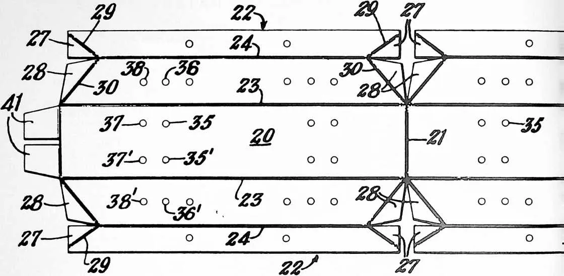 These and other features and advantages of my invention will appear more fully in the
detailed description which follows.
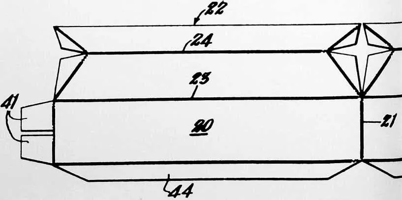
These and other features and advantages of my invention will appear more fully in the
detailed description which follows.
19 Description
20 In the drawings:
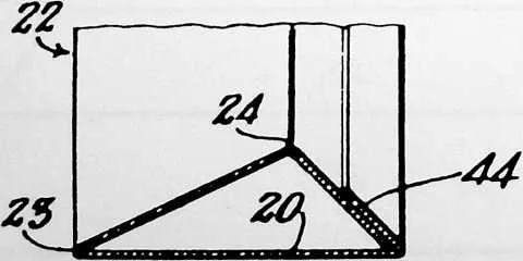
21 Fig. 1 is a face view of a paperboard blank designed to be folded into a triangular frame with hollow sides, representative of the best mode contemplated by me of carrying out my invention.
22 Fig. 2 is an enlarged cross-sectional view along the line 2--2 of Fig. 1.
23 Fig. 3 is a view similar to Fig. 2, illustrating the first part of the operation of folding the blank.
24 Fig. 4 is a similar view illustrating a more advanced stage of the folding operation.
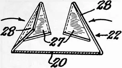
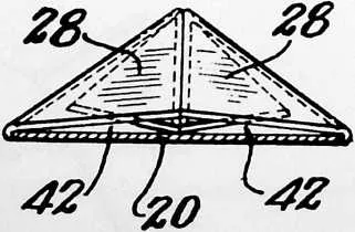
25 Fig. 5 is a similar view illustrating the form of the end of one of the hollow sides of the polygonal frame at the completion of the folding operation.
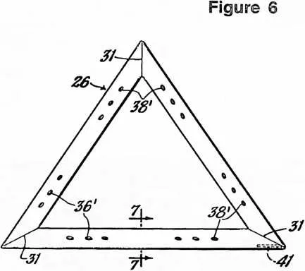
26 Fig. 6 is a face view of the completed triangular frame.
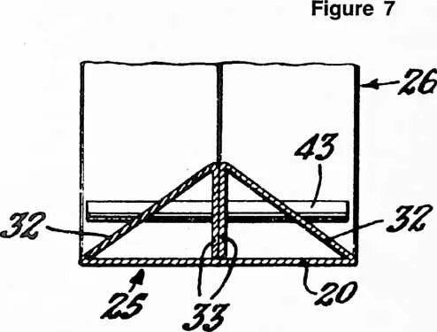
27 Fig. 7 is an enlarged cross-sectional view taken on the line 7--7 of Fig. 6.
28 Fig. 8 is a view illustrating one way in which triangular frames formed in the manner illustrated in the preceding views can be assembled as part of the frame of a building.
29 Fig. 9 is an enlarged cross-sectional view taken as indicated at 9--9 in Fig. 8.
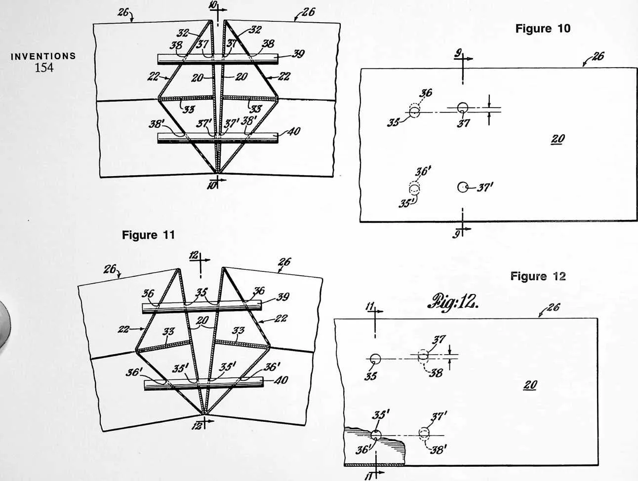
30 Fig. 10 is a side elevational view of one of the component frames of Fig. 9, taken as indicated at 10--10 in Fig. 9, with the alignment pins removed.
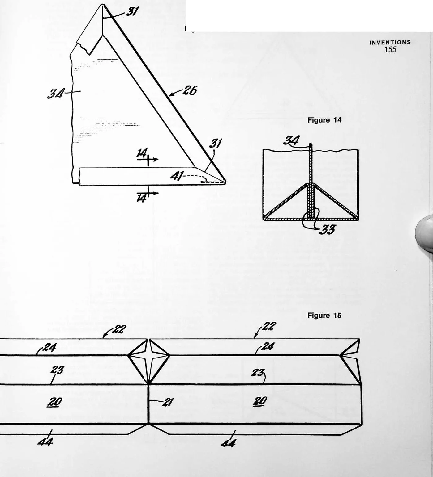
31  Fig. 11 is a view similar to Fig. 9, illustrating another alignment of the component
frames.
Fig. 11 is a view similar to Fig. 9, illustrating another alignment of the component
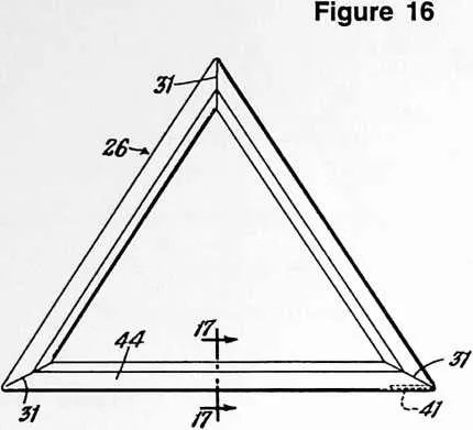
frames.
32 Figure 2
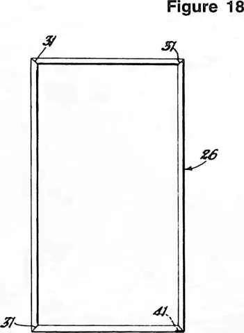
33 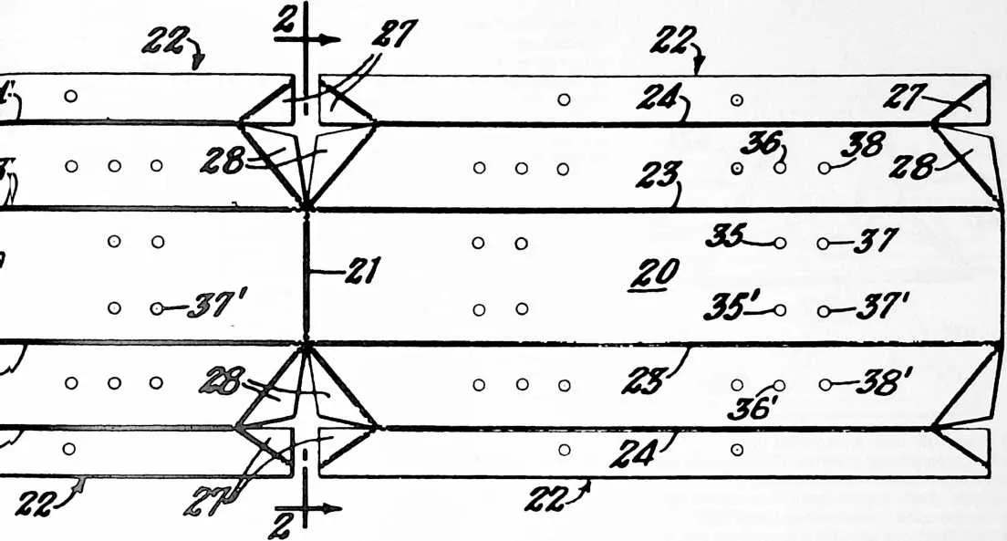 Fig. 12 is a side elevational view of one of the component frames of Fig. 11, taken as
indicated at 12--12 in Fig. 11, with the alignment pins removed.
Fig. 12 is a side elevational view of one of the component frames of Fig. 11, taken as
indicated at 12--12 in Fig. 11, with the alignment pins removed.
34 Figure 1
35 Fig. 13 is a view of a portion of a frame similar to that shown in Fig. 6, and having a panel closing the central opening thereof.
36 Fig. 14 is an enlarged cross-sectional view taken as indicated at 14--14 in Fig. 13.
37 Fig. 15 is a face view of a paperboard blank of a modified construction.
38 Fig. 16 is a face view of a building construction member formed from the blank of Fig. 15.
39 Fig. 17 is an enlarged cross-sectional view taken on the line 17--17 of Fig. 16.
40 Fig. 18 is a face view of a building construction member having four sides instead of three, formed from a blank similar to that shown in Fig. 1 or that shown in Fig. 15.
41 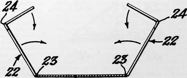 Referring to Fig. 1, my invention comprises, in its general arrangement, a building
construction member
Referring to Fig. 1, my invention comprises, in its general arrangement, a building
construction member
42 Figure 3
43 20
45 Figure 4
46 formed essentially from a single flat piece of paperboard or the like, comprising a series of elongated panels 20 arranged end to end, transverse fold lines 21 between the meeting ends of said panels, and lateral extensions 22 adjoining the elongated panels along longitudinal fold lines 23 and including fold lines 24 spaced from and substantially parallel to the fold lines 23, the lateral extensions folding about the longitudinal and parallel fold lines (Figs. 3, 4 and 5) to form a hollow box-like structure 25 (Fig. 7) which in turn folds about the transverse fold lines 21 to bring the outer ends thereof together to form a polygonal frame 26 (Fig. 6) with hollow sides. The ends of the lateral extensions preferably are formed with flaps 27 and 28 infolding along diagonal fold lines 29 and 30 to form abutting mitered surfaces 31 at the ends of the hollow sides of the triangular, or other polygonal, frame. As shown, these flaps are formed in pairs with the respective members of each pair located at opposite sides of the aforesaid parallel fold lines 24.
47 The angle of the diagonal fold lines 29 and 30 will depend upon the number of sides there are to be in the polygonal frame and, more specifically, upon the vertex angle, or angles, between each two sides, and the angle of these diagonal fold lines is additionally gauged (after taking account of the number of sides, i.e. the vertex angles) to ‘‘crowd’’ the folded lateral extensions 22 within the perimeter panels 20, 20, etc., of the polygon and set up the mitered joints of the polygon under a degree of pressure. This has the result of locking the several com-
49 Figure 5
50 ponents of the frame together for maximum strength as a unit, and tends to distribute stresses encountered by any one part of the frame to the other parts thereof. This may be due in part at least to the fast that the perimeter panels 20, 20, etc., are placed under a degree of tension. Whatever the cause, I have found that building construction members made as I have described, possess astonishing strength, particularly when they are assembled in a generally spherical form in such a manner that the sides of the polygons lie substantially in planes whose intersections with the spherical surface define great circles of that surface. Means are provided for securing together the outer ends of the hollow box-like structure. In the preferred construction shown, a pair of end flaps (Fig. 1) 41 are formed as extensions of one of the perimeter panels 20 to be tucked into openings 42 (Fig. 5, and cf. also Fig. 6). Adhesive tapes or other securing means (not shown) may also be applied around the meeting ends of the structure.
51 In my preferred construction, additional strength is imparted by providing the lateral extensions 22 at both sides of the elongated panels 20. These extensions are folded first diagonally inwardly as shown at 32 in Fig. 7, and
53 then outwardly to form a central reinforcement 33, 33 comprised by the outwardly folded portions of the lateral extensions. These outwardly folded portions bear at their ends against the inside of the elongated panels 20 and divide the box-like structure into two triangular compartments. If desired, a locking pin or pins 43 may be provided, extending through suitable openings formed in the portions 32 and 33 of the lateral extensions.
54 The manner in which the lateral extensions 22 and their infolding flaps 27, 28 are folded to form the hollow box-like structure is further revealed in Figs. 2, 3, 4 and 5. In the first three of these views, the arrows denote the directions of folding. Flaps 27 go inside of, and reinforce, flaps 28 to form the abutting mitered surfaces 31 to which reference has been made.
55 Figs. 13 and 14 show how a panel 34 may be used to close the center of the polygonal frame, the outer portions of this panel being received between the outwardly folded portions 33, 33 of the lateral extensions 22. By inserting panel 34 during the operation of folding the sides of the hollow box-like structure about the transverse fold lines 21, the panel is permanently locked in place. This panel further serves to reinforce the construction, and it may be made of any desired material such as paperboard, beaver board, plastic, aluminum foil, etc., and may be opaque, translucent, or transparent in accordance with the functions to be served, i.e. whether for letting in, or obstructing the passage of, light, conducting, or insulating against the passage of, heat, etc.
56 The modified construction illustrated in Figs. 15, 16 and 17 is substantially identical with the preferred form described above, with the exception that the lateral extensions 22 are present on only one side of the elongated panels 20, and are replaced by flaps 44 which are secured to extensions 22 in the overlapping relation shown in Fig. 17, as by means of a plastic, or other, adhesive, or by means of metal staples, or both, or otherwise, as desired,
57 In Fig. 8 I have shown a group of six triangular frames, which may be of either of the types disclosed in Figs. 6 and 16, assembled to form a hexagon according to one of the sub-components of a building construction framework made in accordance with my prior Patent No. 2,682,235, aforesaid. Other arrangements are possible so as to form, for example, diamonds made from two triangular frames secured together back to back, or pentagons made from
59 five triangular frames secured together in rosette fashion similar to Fig. 8 (compare Figs. 2 and 5 of my patent aforesaid, with reference to the pentagon at the zenith Z and at each junction of the vertexes of the great circle triangles of the spherical icosahedron).
60 Fig. 18 shows another of the many possible forms of polyhedral building construction members which can be formed in either of the manners described, i.e. by utilizing blanks of the general form of either Fig. 1 or Fig. 15. In this case one additional perimeter panel 20 is added to the blank and the lengths of the respective panels are adjusted to the desired measurements. It may be observed here that my building construction members have been found suitable not only for use as components of building frames in which the members form a permanent part of the structure, but also may be used as temporary supporting members in constructing openings such as doors, windows, etc., in erecting buildings of conventional types.
61 In assembling my improved construction members, various arrangements are possible for holding the members together; I have employed wooden pins, both alone and in conjunction with metal clips. Also, I have found it
62 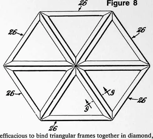 pentagon, and hexagon assemblies, by passing glass fibre tapes around the complete
periphery of the diamond, pentagon or hexagon. Such glass fibre tape is available as a ‘‘Scotch’’
tape and is exceedingly strong in tension, thus contributing importantly to the over-all strength
of the completed framework, particularly when it is constructed in accordance with my prior
Patent No. 2,682,235, aforesaid. In such constructions the several components so complement one
another in the particular pattern of the finished assembly as to enable it to withstand high
stresses, and the framework itself acts almost as a membrane in absorbing and distributing
loads.
pentagon, and hexagon assemblies, by passing glass fibre tapes around the complete
periphery of the diamond, pentagon or hexagon. Such glass fibre tape is available as a ‘‘Scotch’’
tape and is exceedingly strong in tension, thus contributing importantly to the over-all strength
of the completed framework, particularly when it is constructed in accordance with my prior
Patent No. 2,682,235, aforesaid. In such constructions the several components so complement one
another in the particular pattern of the finished assembly as to enable it to withstand high
stresses, and the framework itself acts almost as a membrane in absorbing and distributing
loads.
63 151
64 Another feature of my present invention resides in the provision of means for predetermining the correct angular relationship between each building construction member and its neighbors. This feature will be described with reference to Figs. 9 to 12 inclusive. Fig. 9 is an enlarged detail cross-sectional view taken as indicated at 9--9 in Fig. 8 and shows two triangular frame members 26 back to back, or substantially so. The construction of these frame members is the same as has been described with reference to Figs. 1 to 7 inclusive. The elongated panels 20 and lateral extensions 22 of one of the frames 26 are provided with perforations to receive alignment pins extending through similar perforations in the other polygonal frame 26 of like construction. These perforations are slightly out of alignment with the planes of the respective frames to predetermine the angular relationship of the two frames. More than one set of such perforations may be provided so that by selecting a particular set, one particular angular disposition of the adjacent frames is obtained whereas by selecting a different set of perforations, another angular disposition of the adjacent frames is obtained. Thus, by following a plan or set of specifications indicating the correct placement of the pins, structures of predetermined form are obtained without requiring knowledge or skill on the part of the workmen. I prefer to form the perforations by making cut lines in the paperboard without punching out the centers. Then, by punching out only those openings through which pins are to be passed during erection of the structure, the correct relation of the several components will be obtained without even the need to examine the specifications on the job.
65 Referring further to Figs. 9 to 12 inclusive, it will be observed that I have provided a building construction
68 Figure 9
71 Figure 13
74 NVENT10NS
75 156
76 through the punched out perforations 37, 38 of Figs. 9 and 10, the condition illustrated in Fig. 9 is obtained, whereas by placing the pin 39 in the punched out perforations 35 and 36 of Figs. 11 and 12, the condition illustrated in Fig. 11 is obtained. In the first instance the angularity between the planes of the two frames is slight whereas in Fig. 11 the angularity is somewhat greater. The difference in the two angularities has been shown with considerable exaggeration in these views in order to reveal the principle of operation more clearly. It will be understood that additional apertures may be provided in order to afford a larger range of angular relationships to choose from. The gore between the backs of the two frames may, if desired, be filled with a triangular paperboard element or other filler piece. Also, a metal band or clip may be passed around the meeting edges or corners of the frames to be held in place by the alignment piece, or otherwise, as may be desired.
77 A second set of perforations 35', 36', and 37', 38' may be employed to receive, selectively, an additional pin 40,
79 member of the character described, in which the elongated panels 20 and lateral extensions 22 are provided with a number of perforations, the alignment of which, when the member is set up for use, being as follows: one perforation 37 in a panel 20 opposite a perforation 38 in an extension of such panel comprising one pair of perforations to receive an alignment pin 39, and another perforation 35 in said panel 20 opposite another perforation 36 in said extension of such panel comprising a second pair of perforations alternatively to receive alignment pin 39, the pin axis of said one pair of perforations being at a slight angle to the pin axis of said second pair of perforations, and the pin axis of at least one of said two pairs being at a slight angle to the plane of the polygonal frame. In the example illustrated in Figs. 9 and 10, one of the two pairs of perforations, viz. perforations 35, 36 is blind, while the other pair, viz. perforations 37, 38 is completely punched out selectively to predetermine the angular relationship between said frame and another frame of like construction. In the example illustrated in Figs. 11 and 12, perforations 35 and 36 have been completely punched out while perforations 37 and 38 are blind, to predetermine another angular relationship between the two frames. Thus, by placing the pins 39
81 Figure 17
82 and it may be understood that as many additional sets of such perforations can be used as will be best suited for a particular utilization of my invention.
83 In summarizing my invention at the beginning of this specification, I have referred to the coating of the frames, or the paperboard from which they are formed, with a thin plastic film, such as a vinyl resin, which can be brushed, sprayed, or otherwise applied. I have found that a surprising degree of strength can be imparted to the paperboard structure by the use of vinyl plastic films which are on the order of */i6 inch to */64 inch in thickness, although other thicknesses may be employed as desired, and the frames can be used without any coating whatsoever, particularly if an impregnated or waterproof paperboard is employed.
84 The terms and expressions which I have employed are used in a descriptive and not a limiting sense, and I have no intention of excluding such equivalents of the invention described, or of portions thereof, as fall within the purview of the claims.