
5 DYMAXION BATHROOM (1940)
2U.S. PATENT—2,220,482
APPLICATION—MAY 12, 1938
SERIAL NO.—207,518
PATENTED—NOVEMBER 5, 1940
3 Bn the original 4d house, I planned to introduce all accessories such as bathroom functions in one prefabricated unit, this unit to be hung-swung into position as we would hang a corner cabinet, with gravity holding it firmly in place. I developed the first full-scale working prototype of the bathroom for American Standard Sanitary Heating and Plumbing Company in 1930 and developed twelve new prototypes six years later for the Phelps Dodge Copper Company, then the third-largest copper company in the world. One of these twelve units was set up at the U.S. Bureau of Standards where it was tested for two years, and it was found to conform satisfactorily to all U.S. building codes, but Phelps Dodge, as a copper company, decided not to go into production of the unit.
4 This bathroom unit was designed to be produced not in metal but in glass-reinforced plastic. This production took place in Germany years later, apparently following my drawings, as the unit produced was exactly as I designed it in 1937, although my patent had long since expired.
5 UNITED STATES PATENT OFFICE
6 Richard Buckminster Fuller, New York, N.Y., assignor to Phelps Dodge Corporation, New York, N.Y., a corporation of New York
7 PREFABRICATED BATHROOM
8 This invention relates to a prefabricated building unit suitable for use as a bathroom.
9 Attempts have been made heretofore to provide prefabricated bathrooms with the object of lowering the cost of building a bathroom into a dwelling. Such bathrooms, however, by reason of their great weight and more or less conventional construction have involved relatively high costs by the time they have been shipped and installed ready for use. Furthermore, such bathroom units as heretofore known have been largely designed for introduction into a new building under construction and have not been particularly practical for installation in a dwelling already built without involving too great an expense.
10 It is an object of my invention to provide a compact, light, prefabricated bathroom which may be readily installed either in a dwelling under construction or in a dwelling that is already built.
11 It is another object of this invention to provide a prefabricated bathroom of such a compact construction that it can be separated into a few sections which may be readily carried by hand through a doorway and up a staircase of the average house.
12 It is another object of this invention to provide a prefabricated bathroom fashioned from a relatively few units made of sheet material to provide an integral structure light in weight but having the requisite strength and rigidity when assembled.
13 A further object of my invention is to provide prefabricated bathroom sections of sheet metal having bathroom fixtures formed integrally therewith.
14 Another object of this invention is to provide a two chamber prefabricated bathroom, one chamber being suitable for use as a lavatory and water closet, and the other chamber being useful as a combined tub and shower, and either of these chambers being useful alone.
15 Further objects and advantages of my invention will be apparent from the following detailed description of the embodiments thereof illustrated in the accompanying drawings, in which:
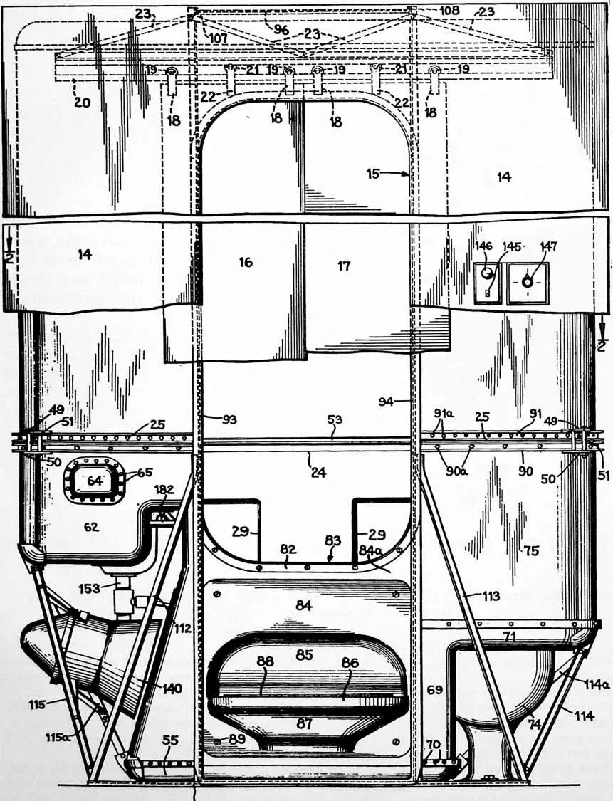
16 Figure 1 is a front elevation of my preferred bathroom as assembled with the lower portions of the outer front decorative panel and the doors broken away;
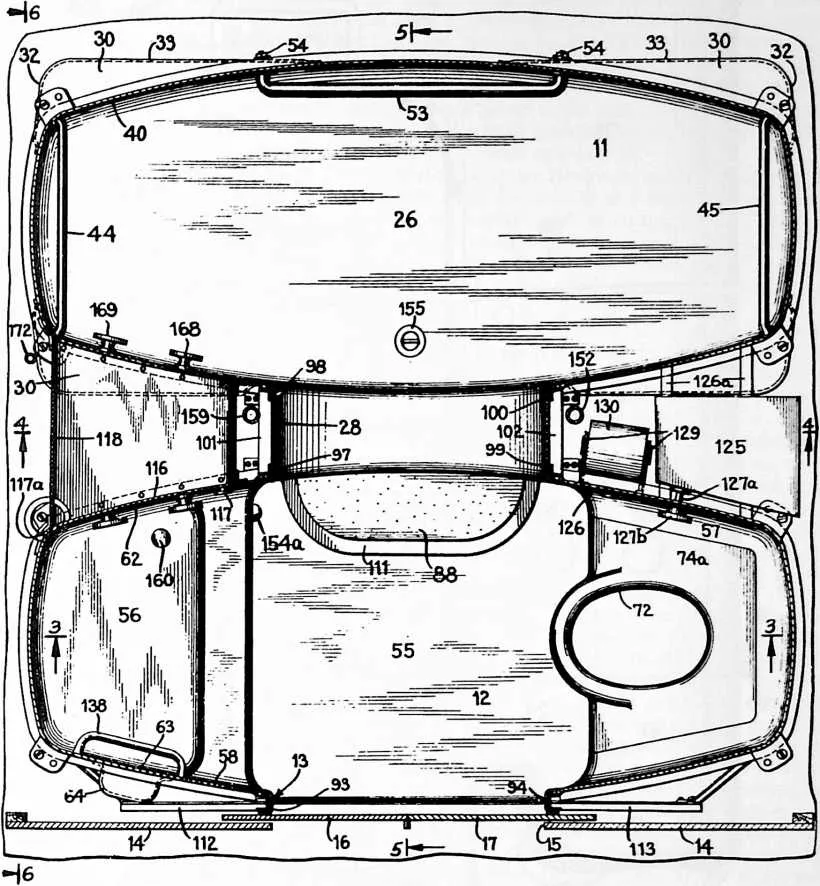
17 Figure 2 is a horizontal cross section of my completed bathroom in installed position, taken about on the offset line 2—2 of Figure 1;
18 Figure 3 is a vertical cross section through approximately the center of the lavatory and water closet, or outer chamber of the bathroom, taken about on the line 3—3 of Figure 2;
19 Figure 4 is a vertical cross section of my bathroom,
20 FIGURE 1
21 95
23 FIGURE 2
24 43
26 taken approximately on the line dividing the two chambers thereof, such as the line 4—4 of Figure 2;
27 Figure 5 is a vertical cross section through approximately the center of my bathroom and at right angle to the section line 2—3 and 4--4, taken approximately on the line of 5--5 of Figure 2;
28 Figure 6 is an end elevation of the two chambers of my bathroom as it appears from the left-hand side of Figure 1;
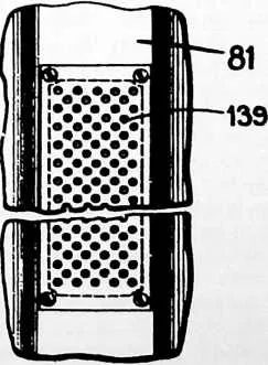
29 Figure 7 is a detail view of a ventilating grill in the doorway of the bathroom connecting the two chambers thereof and taken on the line 7--7 of Figure 3.
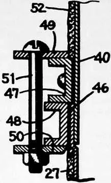
30 Figure 8 is a vertical section of a detail of the bathroom constructed on an enlarged scale, and taken through the junction of the upper and lower sections of the bathroom, showing the manner of clamping the upper and lower sections of each chamber together;
31 Figure 9 is a perspective view partly broken away illustrating a modification of my bathroom with the upper portion thereof comprising the walls of the room in which the unit is installed; and
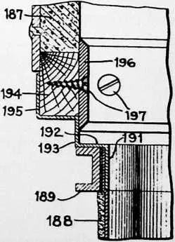
32 Figure 10 is a vertical sectional view of a detail on an enlarged scale showing the way the upper edge of the bathroom in Figure 9 is joined to the walls of the room and taken about on the line 10--10 of Figure 9.
33 With reference, more particularly, to Figures 1 to 8, inclusive, of the drawings, my bathroom is preferably constructed with two chambers of similar shape in horizontal cross section. These two chambers are indicated generally by the numerals 11 and 12. The outer chamber 12 is designed as a lavatory and water closet, and is provided with a doorway 13 permitting entrance into the chamber from an adjoining room of the dwelling. The side of the chamber 12 containing doorway 13 may be concealed from the adjoining room by the fixed vertical panel 14 provided with an opening 15, which may be constructed of metal, wood, Bakelite, or other plastic or composition material. The panel 14 may be rigidly attached to the chamber 12 of the bathroom, although it is preferably provided as a separate unit which may be affixed to and supported by the adjacent portions of the dwelling. Between the panel 14 and the doorway 13 of chamber 12, sliding doors 16 and 17 have been illustrated, it being understood that other forms of doors could be employed if desired. Sliding doors have the advantage, however, of space economy that is not obtained with a hinged door, and they may be used where a hinged door would not be practical. The sliding doors 16 and 17 are designed so that they may be moved outwardly away from each other, sliding into the space between the outer wall of chamber 12 and the panel 14 to leave an opening registering with doorway 13 and the panel opening 15. The sliding doors 16 and 17 may be hung by means of suitable straps 18 fixed to them and carrying the rollers 19 which rest on the track 20 and support the weight of the
34 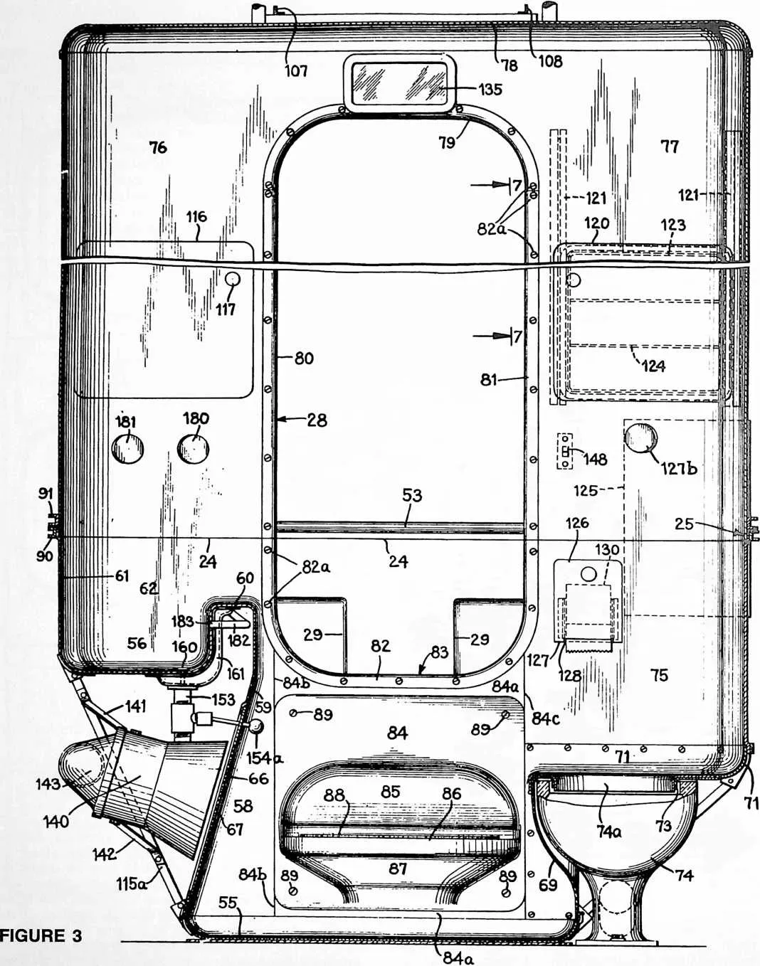 sliding doors. Track 20 may be formed with the shape of a block C in cross
section and the rollers 21 carried on straps 22 intermediate the straps 18 on the doors
bear against the upper inside portion of the track 20 to prevent dislodgement of the
doors from the track by accident. The track 20 may be conveniently suspended from a
framework for the chamber 12 described below and rigidly supported by the diagonal braces
23.
sliding doors. Track 20 may be formed with the shape of a block C in cross
section and the rollers 21 carried on straps 22 intermediate the straps 18 on the doors
bear against the upper inside portion of the track 20 to prevent dislodgement of the
doors from the track by accident. The track 20 may be conveniently suspended from a
framework for the chamber 12 described below and rigidly supported by the diagonal braces
23.
35 The bathroom chambers 11 and 12 may be conveniently constructed with their lower portions or sections made of sheet material such as sheet metal or thin-walled plastic material and with their upper portions formed from a lightweight metal sheet or from suitable plastic or composition material to provide as light a weight as possible. In order to provide as much strength as possible both the upper and lower sections of the chambers may be conveniently made of sheet metal such as copper, aluminum, or steel or a combination of two of them. These upper and lower portions of chambers 11 and 12 are illustrated as joined along the horizontal line 24 and held in
36 assembled position by a suitable clamping arrangement 25 to be described in detail hereinafter.
37 The floor of the bathing chamber 11 may be formed from a single sheet 26 of thin metal such as copper, stamped or drawn into the shape illustrated in Figures 2 and 5, with its edges curving upwardly to form the lowest portions of the chamber walls. The remainder of the lower section of this chamber 11 may be formed from a single sheet 27 of the same metal bent or stamped to expand from below the center of the doorway 28 entirely around the chamber 11 and back to the center of the doorway 28 where the ends of the sheet are joined in the vertical seam 29a. This sheet 27 is preferably shaped to provide all four walls of the chamber 11 curved outwardly about relatively long radii, these walls being joined at the corners by coved portions curved about comparatively short radii.
38 Intermediate the top and bottom of the metal sheet 27 forming the side walls, at a suitable height above the floor, four openings 29 of rectangular shape are formed in the sheet 27. These openings 29 are covered by pocket members 30 stamped out of sheet metal and secured to the outer surface of sheet 27 by riveting, welding or the like. The pocket members 30 are preferably formed with relatively flat lower surfaces 31 and relatively straight side and end walls 32 and 33. When these pockets are sufficiently shallow, they may be stamped or otherwise formed integrally with sheet 27. However, these outwardly extending pockets are preferably formed of separate sheets of metal attached to the outside of the main sheet 27 by the rivets 34, with suitable provision being made at the juncture of the layers of metal to form a water-tight joint having a flush surface inside the chamber 11. Similarly, the bottom metal sheet 26 of chamber 11 may be provided with an offset upper edge 35 so that the lower edge of sheet 27 will be flush therewith on the inside of the chamber, and these two sheets may be secured together in a similar manner by the rivets 36 or by welding or the like. The pockets 30 are constructed to provide the lower wall portions of the chamber 11 with increased rigidity and strength, even though very lightgauge metal may be used in making the walls and floor. In addition, these pockets serve as convenient supports for soap and other bathing accessories, and also as arm rests or supports to assist one in sitting down or rising in the chamber 11 when using it as a tub.
39 The floor of the bathing chamber 11, that is the lower portion of sheet 26, is preferably supported on a suitable wooden platform 37 raised on legs 38 made of angle iron or other material, so that the floor of this chamber is about nine inches above the level of the floor of the chamber 12. The metal sheet 26 may be separated from the wooden platform 37 by a layer of insulation 39, if desired. This arrangement provides adequate room for plumbing and also enables the bottom of the bathing chamber 11 to be cleaned more easily by a person standing in chamber 12.
40 The upper portion of the chamber 11 comprising the walls 40 and the ceiling 41, may be constructed of the same or different material. This upper portion of the bathroom unit is preferably made of a material as light in weight as possible, while still providing the desired strength, rigidity, and pleasing appearance to the entire structure. Various substances may be suitable for this purpose, although I have found that alloys of aluminum or thin sheet steel are particularly satisfactory when the lower portion of the bathroom unit is constructed of sheet copper. The upper portion of chamber 11 may be formed, for example, from a sheet 40 of light-gauge steel or a strong aluminum alloy providing curved end and side walls which are extensions of the lower walls formed from sheet 27. Sheet 40 may extend from the horizontal juncture line 24 to the juncture of this sheet with the ceiling 41 at 42. The ceiling member 41 may similarly be constructed from a single stamped sheet of metal or other material and attached to the side wall 40 by the riveted joint 43 in the same manner that the base sheet 26 is attached to the lower side wall 27.
41 To lend the structure increased rigidity, I prefer to attach firmly inside the sheet 40 at a suitable height above the floor, the rods 44 and 45 extending across the ends of this section. The ends of these rods may be welded or otherwise rigidly secured to the sheet 40 and serve to brace it inside, as well as to provide towel racks and hand grips.
42 The upper portion of chamber 11 comprising the wall sheet 40 and the ceiling member 41 form one prefabricated unit section which is fitted to the lower section as a unit when the chamber 11 is assembled. For this purpose, an outwardly opening channel member 47 may be shaped and riveted to the outer surface of 40 spaced a small distance from its lower edge. A similar rigid channel member 48 may be riveted to the outer surface of sheet 27 adjacent its upper edge. The joining of these walls in assembled position of the units forming chamber 11 is best illustrated in Fig. 8, from which it will be seen that the upper edge of the metal sheet 27 is provided with an offset portion 46 so that the lower edge of sheet 40 below the channel member 47 overlaps therewith to provide a substantially flush interior surface for the chamber 11.
43 In this manner, the sections of the chambers 11 and 12 above the line 24 may be prefabricated as integral units and the sections below the line 24 may likewise be prefabricated as integral units. These unit sections may then be readily transported and assembled in the desired location by clamping the two channel members 47 and 48 together. This might be accomplished by simply bolting the adjacent flanges of the channel members together, although I prefer to employ a clamp consisting of the upper and lower plates 49 and 50 held together by a suitable bolt or bolts 51. These clamping plates 49 and 50 are simply applied to the uppermost and lowermost surfaces of the channel members 47 and 48, respectively, and held in position by tightening the bolts 51. To deaden reverberations within the chambers 11 and 12 and to avoid any hollow metallic sounds, a dope material such as a mixture of asphaltum and asbestos 52 may be applied to the exterior surfaces of the various units either prior to assembly or after assembly. Other materials could be employed for this purpose.
44 Along the solid or innermost wall of the chamber 11, a further bracing rod 53, which may be used to provide additional rigidity to the side wall structure, is preferably attached inside the lower edge of metal sheet 48. The rod 53 may be secured in place by bolts extending through the channel members 47 and 48 and held in place by suitable nuts 54 outside of the channel members. The rod 53 may also be used as a towel rack or as a support to assist one in sitting down or getting up when using the chamber
- 11.
- as a tub. When the rod 53 is held in place as illustrated, it is secured to the chamber wall after the upper and lower units have been assembled.
45 The outer chamber 12 serves as a lavatory and water closet, and communicates with the inner chamber 11 by means of the door 28. The lower portion of this chamber
- 12.
- may be constructed with a metal sheet 55 of copper or the like forming a floor, stamped with upwardly curving edges and having a shape corresponding to the central portion of sheet 26 in chamber 11. In one end of the chamber 12, a wash basin 56 is provided and in the other
46 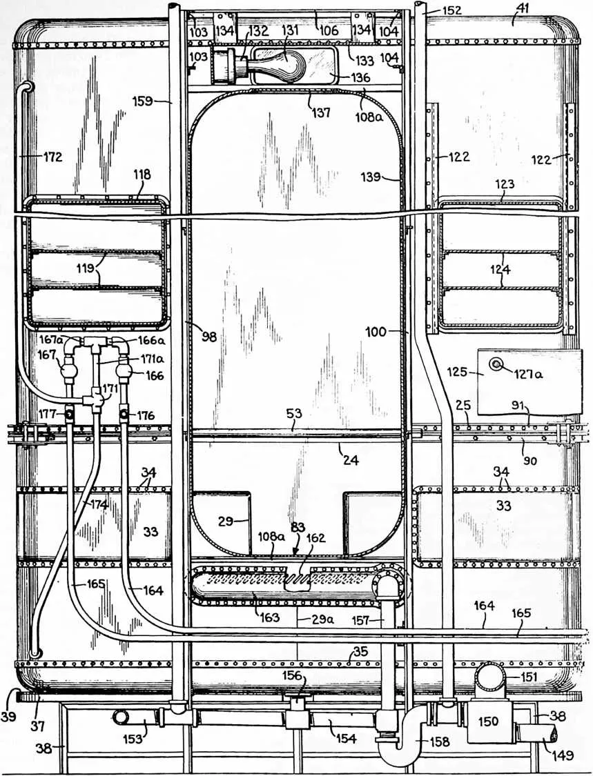 end of chamber 12, a water closet seat 57 is provided formed integrally with
the adjoining walls. The wash basin 56 may be constructed from a single sheet of
metal
end of chamber 12, a water closet seat 57 is provided formed integrally with
the adjoining walls. The wash basin 56 may be constructed from a single sheet of
metal
47 INVENTIONS
48 46
49 FIGURE 4
- 58.
- stamped out to provide an inclined wall 59 extending up from the floor sheet 55 and suitably curved to provide the wash basin with an upstanding forward portion 60 and a vertical curved back wall 61 together with suitably curved side walls 62 and 63. The inclined portion 59 provides adequate foot space for one using the wash basin 56. An opening may be provided in the side wall 63 well above the bottom of the wash basin 56 which is closed by a cup-shaped metal member 64 providing a soap receptacle and affixed to the outer surface of wall 62 by rivets 65, welding or the like. Sheet 58 is also provided with a suitable opening located centrally of the inclined wall portion
- 59.
- and adapted to be closed by the flat plate 66, having suitable perforations 67 therein for a purpose to be described. This plate may be removably attached to the wall portion 59 by the bolts 68.
50 At the other end of chamber 12, a suitably curved sheet of metal 69 may be attached to the edges of the floor sheet 55 by rivets 70 or the like, and provided with upwardly extending curved edges 71 and shaped to provide a horizontal surface having an oval-shaped opening 72. The metal around this opening 72 is preferably bent downwardly as indicated at 73. A porcelain or other suitable water closet bowl 74 may thus be supported immediately below the oval opening 72. I prefer to provide a separate removable sheet of metal 74a which may be coated with porcelain or other suitable metal and which is provided with an oval opening conforming to the opening 72 and fitting thereover. This cover member may be then easily removed for cleaning the water closet bowl or other purposes. The extension of the side walls above the upwardly curved edges 71 of sheet 69 may be formed from a single sheet of metal 75, suitably curved and extending from the line 24 to the upper edge of the metal sheet 65. A portion of sheet 69 on the inner side of cham
51 ber 12 may be removably secured in place, if desired, by the bolts 69a, thereby providing access to the plumbing after the chamber 12 has been assembled and installed.
52 The upper portion of the side walls of the chamber 12 may be formed from lightweight metal, such as aluminum alloy, sheet steel, or plastics or other material, in a similar manner to the upper portion of chamber 11. The sheet 76 may be curved to provide suitable side walls extending above the line 24 as extensions of the walls 61, 62, 63. Another sheet 11 may be suitably curved to provide upward wall extensions from the sheet 75. Openings would thus be left on each side of chamber 12 between the sheets 78 and 71 and the sheets 56 and 75 above panel 84a in the shape of the doorways 13 and 28. The ceiling of chamber 12 may be formed from a single sheet 78 of stamped metal or molded plastics and permanently secured to the upper edges of sheets 76 and 77 as by rivets 78a.
53 When the two chambers 11 and 12 of the bathroom are assembled, the upper and lower sections of each of these chambers may be held together by an upper U-shaped member 79, side wall plates 80 and 81, and the lower U-shaped member 82 forming a frame for doorway 28. These members and plates may be provided with suitable flanges which may be removably attached to the edges of the various sheets defining doorway 28 by the bolts 82a. The lower member 82 thus provides a flat horizontal surface 83 which can be used as a step for stepping from the lavatory and water closet chamber 12 into the bathing chamber 11, or for a seat when bathing.
54 Inside chamber 12 and immediately below the horizontal surface 83, a panel 84 is removably attached to the side wall of chamber 12. This portion of the chamber side wall may be a single sheet 84a having a suitably opening normally covered by panel 24. Sheet 84a may be joined to sheet 58 along the seam 84b, and to sheet 75 along the seam 84c. Panel 84 is preferably stamped or drawn to provide a depression 85 on the inside of the panel, a flat
55 FIGURE 5
56 95
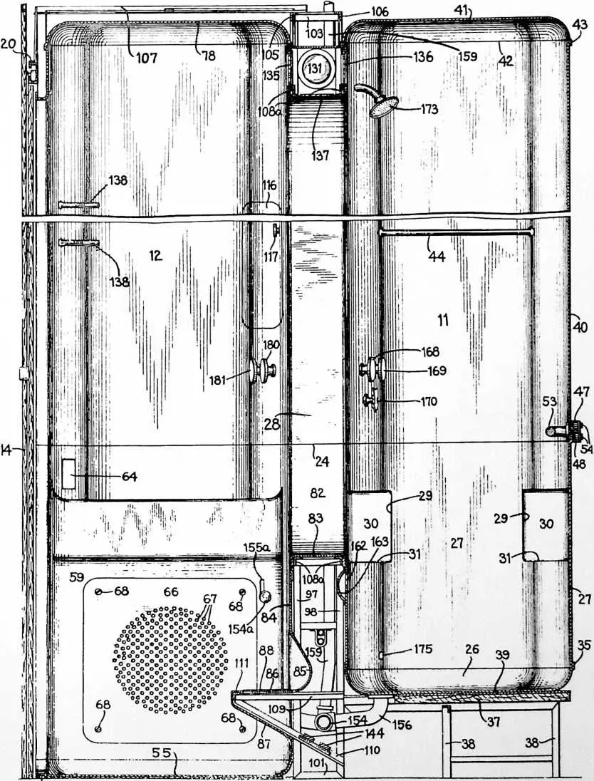
58 horizontal surface 86 of substantial width extending into the chamber below depression 85, and a curved inclined supporting surface 87 immediately below the horizontal surface 86. A mat 88 of pressed cork or the like may be employed on the surface 86, thereby providing a step to facilitate stepping from chamber 12 through the doorway 28 into the bathing chamber 11. Panel 84 may be removably attached to the structure by the bolts 89. The upper side wall and ceiling sheets 76, 77 and 78 of chamber 12 are preferably constructed as a single unit section which may be attached to the lower section of chamber 12 also constructed as a single unit in the same manner as described above in connection with the upper and lower sections of chamber 11. Thus, an outwardly opening channel-shaped member 90 may be affixed to the upper edges of sheets 59 and 75 and the channel member 91 may be affixed near the lower edges of sheets 76 and 77 as by the rivets 90a and 91a respectively, or by welding or
59 FIGURE 6
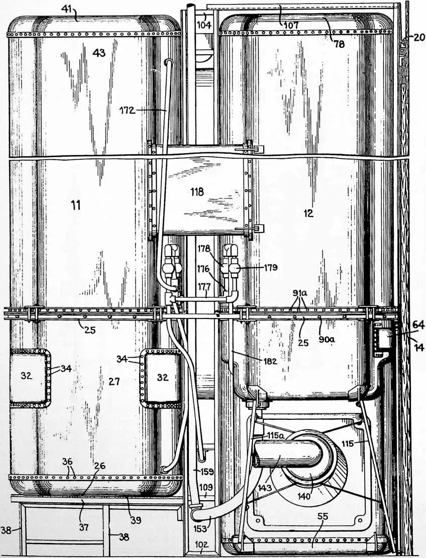
61 the like. These channel members 90 and 91 may be clamped together in any suitable manner when the two sections are assembled, as by the use of the same clamping plates 49 and 50 and bolts 51 as heretofore described for the unit sections of chamber 11.
62 A framework is preferably constructed around the center of chamber 12 and around doorway 28 to provide additional strength. This framework may conveniently be made of lengths of angle iron bolted, riveted, welded or otherwise secured together. For example, the vertical angle irons 93 and 94 joined together at the bottom by a suitable horizontal member 95 provide in effect a frame for the main door 13 to the bathroom. The upper ends of these frame members 93 and 94 may be connected together by a suitable cross member 96. The track 20 for the sliding doors 16 and 17 is preferably separate from this framework but suspended from the top of members
- 93.
- and 94 by the diagonal straps 23.
63 Disposed between the two chambers 11 and 12 is a box-shaped frame constructed around the doorway 28 and made up of the four upright frame members 97, 98, 99 and 100. The frame members 97 and 98 are joined together at their foot by a short cross member 101, and the frame members 99 and 100 are similarly joined together at their foot by a cross member 102. At their top these upright members are connected together by corresponding short angle iron pieces 103, 104 and by the longer angle iron pieces 105, 106. The upper portion of this box frame is preferably connected to the front frame members 93, 94 by the angle iron pieces 107 and 108. The portions of the box frame adjacent the upper and lower ends of doorway 28 may be provided with four horizontal members 108a connecting the upright members 97, 98, 99 and 100 to reinforce the doorway. In the lower portion of this box frame, the horizontal angled pieces 109 braced by the inclined angle pieces 110 and connected by the cross member 111 serve to reinforce the step 86 in the panel 84. This box frame may also advantageously be connected to and form some of the legs for the platform 37 which supports the floor of bathing chamber 11.
64 The front frame made up of vertical members 93 and
- 94.
- may also be braced by the inclined members 112 and 113 connected to the ends of cross member 95 and to intermediate portions of members 93 and 94. The inclined braces 114 and 114a may also advantageously be arranged to brace the sheet metal forming the water closet seat. Brace 114 extends from the end of member
- 95.
- to the nearest upper corner of sheet 57 while brace 114a extends from the inside corner of the floor sheet 55 to the other upper corner of sheet 57. At the other end of
66 FIGURE 7
68 FIGURE 8
69 the chamber 12, the braces 115 and 115a are preferably employed to support the wash basin. Brace 115 may extend from the end of cross member 95 to one upper corner of the wash basin 56 while the other brace 115a extends from the other lower inside corner of sheet 55 to the other comer of wash basin 56.
70 Braces 114 and 115 are preferably pivotally connected at their upper ends so that during transportation of the lower section of chamber 12, the lower ends of these braces may be detached and swung inwardly. These braces are constructed of such a length that their lower ends in this latter position will bear against the lower outside comers of sheet 55 to which they may be attached during transportation, if desired. When the chamber 12 is assembled, the lower ends of braces 114 and 115 may then be swung outwardly and bolted or otherwise attached to the ends of frame member 95.
71 Inside chamber 12, a suitable door 116, provided inside with a handle 117, may be vertically hinged at 117a in an opening in sheet 76. By opening this door 116 inward into the chamber 12, access to a cabinet 113 having suitable shelves 119 is provided. The cabinet 118 is secured to the outside of the sheet 76 between the two chambers 11 and 12. Where the two chambers are to be employed together, this cabinet 118 may advantageously be attached also to the exterior of sheet 40 of chamber 11 as illustrated, thereby serving to hold the two chambers together more rigidly. A mirror may be affixed to the inner surface of door 116 and a light suitably connected to the inner surface of the door above the mirror may be used. Thus the lighted mirror is in the best position for use when the cabinet door 116 is open, and is concealed when this door is closed.
72 At the other end of chamber 12, a similar door 120, suitably hinged to sheet 77, may be provided. Parallel tracks 121 may be secured to the exterior surface of sheet 77 and another pair of tracks 122 may be attached to the outside of sheet 40 of chamber 11 to provide a vertical runway for the cabinet 123 having suitable shelves 124 therein. The advantage of this vertically movable cabinet 123, exposed by opening the door 120, is to provide access to the water tank 125 located immediately below it in case repairs should be necessary. This water tank 125 may be of a suitable shape to fit between the two chambers 11 and 12 and may be supported by the cross members 126a. A rod 127a extending into tank 125 and through sheet 75 and provided inside chamber 12 with a handle 127b may be used for controlling the water in tank 125 to flush the water closet. At one side of this water tank 125, a panel 126 may be provided hinged to sheet 75
73 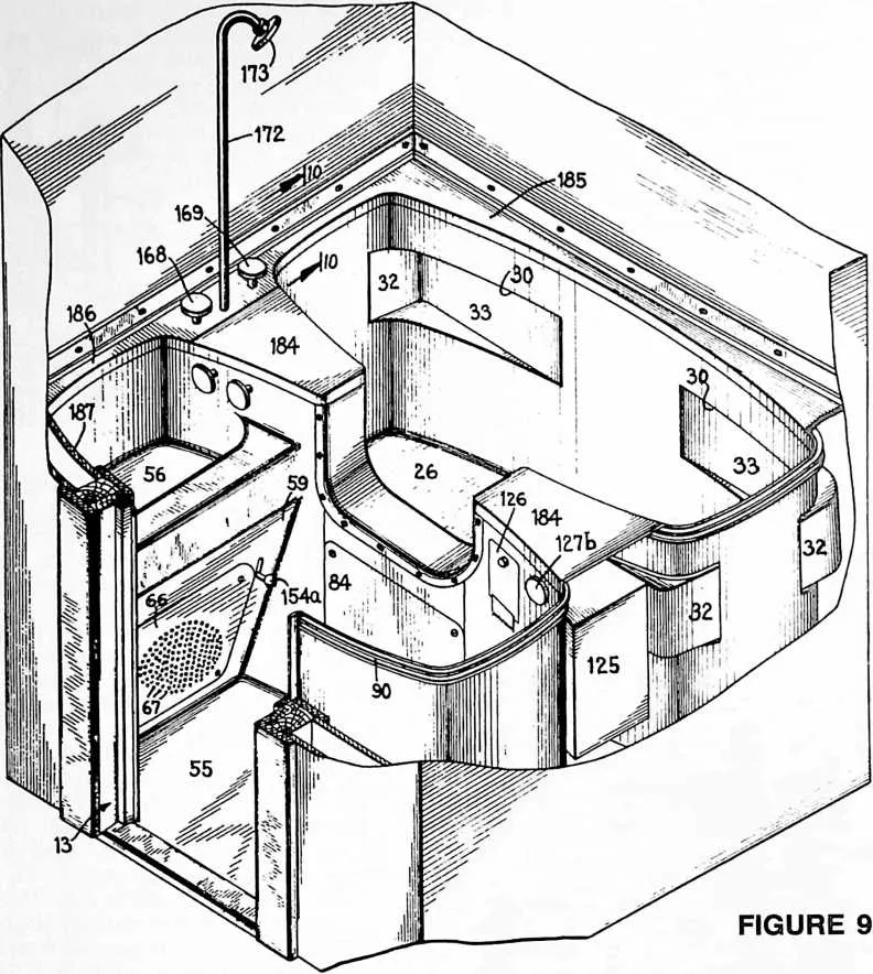 at its lower edge 127 and leaving a narrow horizontal opening 128. On the exterior
surface of this panel 126, a suitable bracket 129 may be provided for supporting a
roll of paper 130. The paper is thus adapted to be threaded through the opening 128
into chamber 12 and roll 130 may be replaced when needed by opening the panel
126.
at its lower edge 127 and leaving a narrow horizontal opening 128. On the exterior
surface of this panel 126, a suitable bracket 129 may be provided for supporting a
roll of paper 130. The paper is thus adapted to be threaded through the opening 128
into chamber 12 and roll 130 may be replaced when needed by opening the panel
126.
74 Light for both chambers 11 and 12 may be provided from a bulb 131. A suitable fixture 132 supported in the frame 133 is suspended between the upper portions of chambers 11 and 12 by suitable strap members 134 from the cross bar 108 of the external angle iron framework. Transparent or translucent panels 135, 136 and 137 may be provided surrounding this bulb so that indirect lighting is supplied from a single bulb to both chambers 11 and 12. Towel racks 138 may be provided in chamber 12 above the wash basin 56 if desired.
75 Ventilation is obtained by drawing air in through the grill 139 removably set into the upper end of frame member 81 of doorway 28. Air and steam may be forcibly drawn downwards and exhausted from the chambers through the perforations 67 in panel 66 by means of a suction fan associated with the hood 140. This suction fan and hood may be supported by suitable straps 141 and braces 142 from the frame members 115 and 115a. The air withdrawn from the chamber 12 may be carried away through conduit 143 and discharged to the outer atmosphere in any suitable way. By this provision for lighting and ventilation, the necessity of using a special ventilator shaft or window for the bathroom is avoided. This is particularly advantageous for large buildings such as apartment houses where a bathroom may be near an air shaft, or when a bathroom is needed in a location of the building where a window would not be practical. Cutting new windows is also obviated with my bathroom when it is used for remodeling a dwelling.
76 Heating of the chambers 11 and 12 may be taken care of by drawing in warm air through the grill 139 from a room in which the bathroom may be installed. I prefer, however, to provide a heating unit under the step 86 such, for example, as the simple resistance heater 144 mounted on the diagonal brace 110. This resistance unit 144 heats the space below the step 86 and the step 83, and when a heat conductive metal, such as copper, is employed for the lower portions of the chambers, heat is readily and rapidly conducted throughout the entire lower section of chambers 11 and 12, thereby providing surfaces lukewarm and pleasant to the touch, as well as serving to heat the entire chambers.
77 The lighting, ventilation and heating may be controlled from inside or outside the bathroom as desired. For example, a switch 145 may be provided on the exterior of the panel 14 outside of the bathroom, together with a signal light 146 to operate simultaneously the heating unit 144 and the light bulb 131. The ventilation fan in hood 140 may be controlled by a three speed switch 147 adj a-
78 cent the switch 145. Alternatively, the heating unit 144 and/or the ventilating fan may be independently operated by a switch 148, or switches, mounted on an inner wall or chamber 12 of the bathroom. As will be readily understood, the electrical connections for the ventilating fan, the light, and the heating unit may be taken from a single cable, which cable is provided for connection to the house lighting system in any suitable manner when the bathroom is assembled and installed.
79 The plumbing connections are preferably arranged in conjunction with a manifold to facilitate connection to the main supply and waste lines of the dwelling. The main waste pipe 149 for the outlet of all waste from the bathroom may be connected through a trap 150 of suitable construction to a pipe 151 which is in turn connected to a side outlet from the water closet bowl 14. This trap 150 may be ventilated through pipe 152 if necessary. Waste water from the wash basin 56 may be withdrawn through the outlet pipe 153. Pipe 153 may be connected to the main pipe 154 which also serves to withdraw waste water from the bottom of the bathing chamber through outlet 155 and pipe 156. The bathing chamber 11 may also be provided with an overflow outlet connected to pipe 157 which joins pipe 154 near the trap 158 connected to trap 150. Another ventilation pipe 159 may be provided for this portion of the waste manifold, if necessary.
80 The handle 154a extending into chamber 12 through the slot 155a may operate a suitable closure 160 in the wash basin 56, which allows water to flow into the auxiliary chamber 161 arranged below the wash basin outlet and connected to pipe 153 to carry away waste water from the wash basin outlet proper and from the overflow outlet for the waste basin. The overflow outlet for the bathing chamber 11 may comprise a series of diagonal openings 162 in the chamber wall immediately below the threshold 83 of the doorway 28. Covering these openings 162 is a stamped metal fitting 163 riveted or otherwise secured in watertight fashion to the pipe 157 and to the outer surface of the wall of chamber 11 between chamber 11 and the chamber 12.
81 Hot and cold water may be supplied for the entire unit through the main supply pipes 164 and 165 suitably bracketed together and supported by the angle iron framework between the two chambers 11 and 12. These pipes 164 and 165 are connected to the valves 166 and 167, operated by the handles 163 and 169, respectively, inside the bathing chamber 11. Immediately below and disposed between these handles 168 and 169 is a third handle 170 which may be in the form of an indicator, and which operates a three-way valve 171. Pipe connections 166a, 167a, and 171a are provided between these three valves. Valve 171 determines whether the hot and/or cold water from valves 166 and 167 flow through pipe 172 to the shower spray 173 in chamber 11, or through the pipe 174 to the opening 175 near the floor of the bathing chamber 11. The hot and cold water inlet pipes 164 and 165 are also connected by branch lines 176 and 177, respectively, to the valves 178 and 179. These valves are controlled by handles 180 and 181 inside the chamber section 12 immediately above the wash basin 56. Hot or cold water or a mixture thereof from valves 178 and 179 flows through pipe 182 to the inlet opening 183 in the side of the wash basin 56 nearest the user. In filling the basin, therefore, the water spurts away from the user, avoiding splashing.
82 It will thus be seen that the prefabricated bathroom of my invention is constructed with the three primary bathroom fixtures, tub, wash basin and water closet seat as integral parts of the floor and walls of the lower one-third of the bathroom. This lower one-third of the bathroom is divided into two sections, one for each of the chambers
- 11.
- and 12 of the bathroom and each of these chambers 11 and 12 may be constructed as two separate prefabricated units including the necessary fixtures. The wall extension and ceiling units, or the upper portions of the two chambers 11 and 12 of the bathroom may similarly be constructed as two separate prefabricated units. The frame members 79, 80, 81 and 82 for doorway 28, the angle iron framework, and the plumbing manifold constitute separate units, together with any accessories of an optional nature, such as cabinets and the other relatively few pieces that require attachment to the various units when the bathroom is assembled.
83 In assembling and installing my new bathroom, the lower unit sections of chambers 11 and 12 are disposed side by side with the lower section of chamber 11 supported on the platform 37, the water closet bowl 74 having been previously bolted or otherwise secured in the proper position. The box frame of angle iron members is placed in correct position between chambers 11 and 12 and the flanged U-shaped doorway frame member 82 is then bolted to the two lower sections of chambers 11 and
- 12.
- to hold them in place. The upper unit section of chamber 11 may now be fitted in place on the lower section and the clamps 49 and 50 applied and secured by bolts 51. The plumbing manifold may now be connected in place to chamber 11 and the main supply and waste lines of the dwelling.
84 The accessories, such as the water tank 125, light bracket 132, cabinets, heating unit, rod 53 and ventilating unit 140 may conveniently be secured in the proper position at this time and connected by any piping or wiring necessary. Finally, the upper section of chamber 12 may be fitted and clamped in place, and the remainder of the angle iron framework may be adjusted. Before securing the doorway frame members 79, 80 and 81 in place, the plumbing connections should be completed and the cabinets and other accessories suitably attached to the walls of chamber 12 as may be necessary.
85 As soon as the doors 16 and 17 are hung, the panel 14 secured in place and the switches carried by it connected, the bathroom is ready for immediate use.
86 I have found that this bathroom can be readily made from integral metal stampings. When the units are constructed with the curved side walls as illustrated in Fig. 2, the various units may be made from stampings of a very light gauge sheet metal, such as copper, while still providing adequate strength. By the curved wall and integral
88 FIGURE 10
89 metal stamping construction illustrated, no comers are left which are difficult to clean.
90 Accessibility to the plumbing and other appliances of the bathroom after assembly is provided through the panels 86, the U-shaped door frame member 82, the panel 84, grill 139 and the vertically movable cabinet 120. Other removable panels may be provided at any points desired.
91 After assembly, or before assembly, the copper sheets of the lower portion of the bathroom unit may be finished as by spraying a metal coating of a corrosion resistant alloy on the surfaces inside the chambers 11 and 12, followed by buffing or polishing the surface to give it a slightly hammered texture which will prevent slipping and provide a surface with a minimum of dirt adherence. An alloy of about 98% tin and 2% silver is suitable for this coating, although other alloys could, of course, be used. If the upper portions of the chambers 11 and 12 are made of some sheet metal such as steel, it may be desirable to employ an insulating material such as a lacquered masking tape at all joints between the steel and copper to avoid the formation of galvanic couples which might promote corrosion. The electrical connections are also preferably grounded to the lower portions of the chambers.
92 The outer chamber 12 of the bathroom may be used alone without the bathing chamber 11 by simply providing a panel for closing off the doorway 27. This chamber 12 may be very suitable for use alone where a ‘‘powder room’’ is desired, or with the bathing chamber 11 in places where space is at a premium, such as in boats, trains and the like. A curtain may be provided for the doorway 28 such as a metal Venetian blind to separate the two chambers when they are used together. Such a curtain as a Venetian blind is particularly suitable because it allows the ventilating system to exhaust steam from the bathing chamber 11, thereby ventilating both chambers at the same time even though both are being used simultaneously. Chamber 11 may also be used alone when the facilities of chamber 12 are not required.
93 The complete prefabricated bathroom with both chambers 11 and 12 is so devised that it may be installed in a room of a completed house as a unit cabinet with or without partitioning off, and without the necessity of providing a window. The whole assembly may be constructed of sheet metal such as aluminum with a total weight of approximately 250 lbs., and made up of separate integrated sections, each of which can be readily carried by two men through the doorway of the ordinary house and assembled ready for use in a few hours. The bathroom may also be installed as easily during the erection of a dwelling.
94 A modification of my bathroom is illustrated in Figs. 9 and 10 and comprises substantially the same construction as described above, with the exception that the portions of the chambers 11 and 12 above the line 24 in Figs. 1--8 are left off and the lower portions of the chambers are capped to conceal the plumbing. The walls of plaster, wood, tile or the like of the house in which the lower portions are installed provide the upward extensions for the walls of the chambers. Similar reference numerals indicate similar parts in Fig. 9 to those described in connection with Figs. 1--8. In this modification, suitable metal capping plates 184, 185 and 186 may be provided to cover the openings between the chamber walls and are preferably removable to get at the plumbing.
95 The shower spray 173 may be attached to the pipe 172 which extends up through the cover plate 186 instead of being between the walls of the chambers 11 and 12 as in Figs. 1--8. The control handles for the shower 168, 169 may also be disposed in the cover plate 186 instead of on the side wall. For this modification, some form of window or ventilator is necessary. The cabinets and other accessories for the room above the line 24 in Figs. 1--8 must also be supplied separate from the prefabricated metal units of the bathroom.
96 For joining the metal of the lower portion of this bathroom unit to a plaster wall 187, such as illustrated in Figs. 9 and 10, the wall 188 of the bathroom unit may have suitable channel members 189 attached to the outer surface adjacent its upper edge. The cover members 190 have flanges 191 depending inside the chambers and lying against the offset upper edge 188 of the chambers to provide a flush interior surface. Horizontal portions 192 of the cover members 190 overlie the channel members 189 extending to the vertical portions 193 in the plane of the plaster wall 187. Wooden members 194 support the lower edge of the plaster and lie flush with it. A further flange 195 of the cover members 190 extends underneath and up along the back of these wooden members 194. These joints and the wooden members 194 are concealed by the strip of beveled metal plate 196 held in place by the wood screws 197. A relatively smooth exterior is thus presented to the room containing the bathroom chamber units. The prefabricated portions of this modification of my invention may, of course, be constructed at less cost and of less weight than the preferred modification although more time may be required under certain conditions for installation.
97 The terms and expressions which I have employed are used as terms of description and not of limitation, and I have no intention, in the use of such terms and expressions, of excluding any equivalents of the features shown and described or portions thereof, but recognize that various modifications are possible within the scope of the invention claimed.