
12 PLYDOME (1959)
2U.S. PATENT—2,905,113
APPLICATION—APRIL 22, 1957
SERIAL NO.—654,166
PATENTED—SEPTEMBER 22, 1959
3 FOUND THAT I COULD TAKE 4' X 8' J plywood sheets and with the spherical trigonometry properly calculated put holes in the plywood sheets to match with the other sheets to produce a geodesic dome.
4 Take a common postcard and, with a ruler and a pencil, make marks at the midpoints of the long edges of the card. Then, with the ruler, connect the two midpoints, dividing the card into two rectilinear halves. Then measure the midpoints of both of the short edges of the postcard. Then, with the ruler, draw four connections between the midpoints of the short edges and the midpoints of the long edges; you’ll find this makes a diamond, not only a diamond but also a line dividing the diamond’s shortest axis, producing two triangles. Now bend the postcard on the four edges of the diamond and the midpoint of the diamond. You’ll find that you can take these postcards, if you do the spherical trigonometry properly, and interconnect them in such a manner as to make three of them make a triangle, and you’ll find they’ll come together to make an icosahedral geodesic sphere. This being so, I saw that plywood could be bent enough in its own right so that with proper holes, located by spherical trigonometry, one could bolt plywood sheets together to form a sphere.
5 UNITED STATES
6 PATENT OFFICE
7 Richard Buckminster Fuller, New York, N.Y.
8 SELF-STRUTTED GEODESIC PLYDOME
9 The invention relates to geodesic and synergetic construction of dome-shaped enclosures.
10 SUMMARY
11 Fundamental concepts of geodesic and synergetic construction are described in my prior patent, No. 2,682,235, granted June 29, 1954, and in my copending applications for patent, Serial No. 563,931, filed February 7, 1956, and Serial No. 643,403, filed March 1, 1957. As the invention of my prior patent has become known and used throughout the world, it can be assumed that the reader will be familiar with geodesic dome construction and the principal characteristics which distinguish it from the older architectural forms; so these characteristics will here be reviewed only briefly. For a comprehensive re-
12 view, reference is made to Patent No. 2,682,235, aforesaid.
13 158
14 In geodesic construction, the building framework is one of generally spherical form in which the longitudinal centerlines of the main structural elements lie substantially in great circle planes whose intersections with a common sphere form grids comprising substantially equilateral spherical triangles. [’’Great circle planes’’ are de-inherently strutted spherical form to produce what we may for simplicity term a self-strutted geodesic plydome. The flat sheets become inherently geodesic; they become both roof and beam, both wall and column, and in each case the braces as well. They become the weatherbreak and its supporting frame or truss all in one. The inherent three-way grid of cylindrical struts causes the structure as a whole to act almost as a membrane in absorbing and
16 fined as planes whose intersections with a sphere are great circles. Such planes pass through the center of the sphere. The earth’s equator and the meridians of the globe are representative of great circles in the ordinary accepted meaning of this term.] The grids can, for example, be formed on the faces of a spherical equilateral icosahedron. Each of the twenty equal spherical equilateral triangles which form the faces of the icosa is modularly divided along its edges. Lines connecting these modularly divided edges in a three-way great circle grid provide the outline for the plan of construction. Each of the smaller triangles formed by the three-way grid is approximately equilateral, i.e. its sides are approximately equal. The extent of variation in length is determined trigonometrically or by graphic solution of the grids as drawn upon the modularly divided edges of an icosahedron outlined upon the surface of a scale model sphere. It will be found that at each vertex of the icosa five of the grid triangles form a pentagon, whereas elsewhere throughout the pattern the grid triangles group themselves into hexagons, this being one of the distinguishing characteristics of three-way grid construction.
17 My present invention arises in the discovery that when perfectly flat rectangular sheets are shingled together in a three-way grid pattern and are fastened together where they overlap in the areas of the geodesic lines of the pattern, a new phenomenon occurs: there are induced in each flat rectangular sheet, elements of five cylindrical struts defining two triangles of the grid edge to edge in diamond pattern. The effect is to produce a three-way geodesic pattern of cylindrical struts by inductive action so that, when the sheets are fastened together in the particular manner described, the struts are created in situ. Thus the flat rectangular sheets are triangulated into an distributing loads, and results in a more uniform stressing of all of the sheets. The entire structure is skin stressed, taut and alive. Dead weight is virtually non-existent. Technically, we say that the structure possesses high tensile integrity in a discontinuous compression system.
18 Description
19 With reference to the accompanying drawings, I shall now describe the best mode contemplated by me for carrying out my invention.
20 FIGURE 2
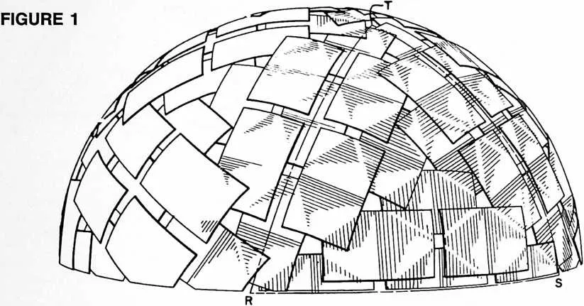
22 Fig. 1 is a perspective view of a geodesic plydome embodying my invention in a preferred form.
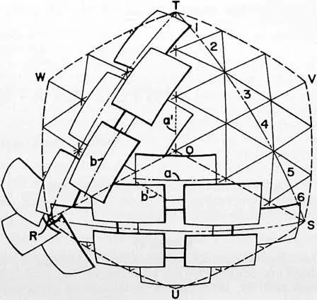
23 Fig. 2 is a detail perspective view of a portion of the Fig. 1 construction overlaid upon a diagrammatic representation of a three-way grid as an imaginary projection of the induced strutting of the dome. The area comprised is representative of one full face of the icosa with adjacent one-third sectors of adjacent faces. Combining the one-third sectors lying at each side of the respective meeting edges of the adjacent faces, we get three ‘‘large diamonds’’; and
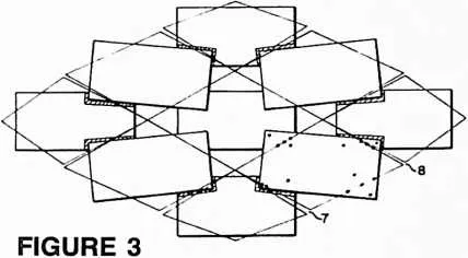
24 Fig. 3 is an enlarged detail view of the sheets which go to make up one of these large diamonds. Here the sheets are shown as they would appear when laid out flat and before they are fastened together.
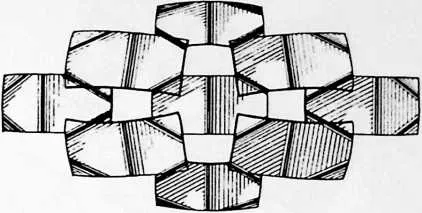
25 Fig. 4 is a view similar to Fig. 3. Imagine that this big diamond is now a part of the completely assembled dome, and notice how the structure has inductively produced five struts in each of the sheets.
27 Figs. 5--8 inclusive, show icosa segments of several modified constructions in which pyramidal groupings of the triangular grid faces defined by the induced struts produce in and out convolutions of the spherical surface. In these several constructions the apexes of the pyramids define one sphere and the bases of the pyramids another. Which of the two spheres is the larger depends on whether the apexes of the pyramids project outwardly or extend inwardly. The sides of the pyramids may be regarded as struts connecting elements of the inner and outer spheres and thus creating a truss.
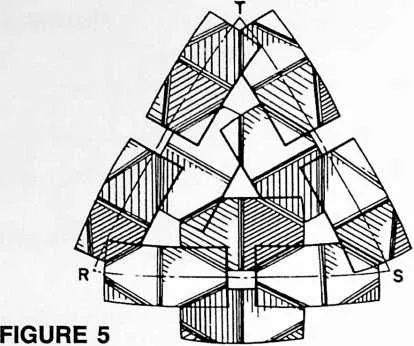
28 Fig. 5 follows the same sheet arrangement as in Figs. 1--4. Because of the convoluted, or involute-evolute construction, we get hexagonal and pentagonal pyramids (pentagons at the vertexes of the icosa), which for simplicity I term a hexpent configuration. Here the apexes of the hexes and pents project outwardly (or upwardly from the plane of the drawing). Notice that a strut is induced along the short axis of each sheet.
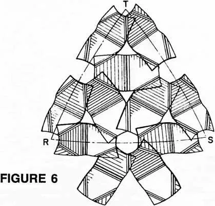
29 Fig. 6 shows a modified hexpent pattern in which the sheets ‘‘toe in’’ to the apexes of the pyramids.
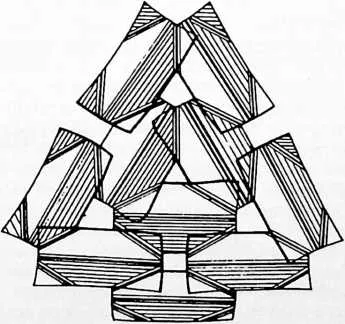
30 Fig. 7, like Fig. 5, has the same sheet arrangement as in Figs. 1--4. Here the induced geodesic triangles of the sheets form an inverted tetrahedron at the center of each face of the icosa, and one of the induced struts extends the long way of each sheet.
31 Fig. 8 has a sheet arrangement which may be compared to that of Fig. 6, but with one of the struts extending the long way of the sheet there is formed a pattern of inverted hexpent pyramids.
32 The construction shown in each of Figs. 5 to 8 inclusive may be turned inwardly or outwardly. For example if we think of Fig. 5 as representing the outer surface of a dome, we have pyramids projecting outwardly with their
33 FIGURE 4
35 apexes in an outer sphere and their bases (or the comers of their bases) in an inner sphere. Or if we think of Fig. 5 as representing the inner surface of a dome, we have pyramids extending inwardly with their apexes in an inner sphere and their bases (or the comers of their bases) in an outer sphere.
36 In Figs. 1, 2, 5 and 6, the dot and dash lines RST represent one of the equilateral spherical triangles of a spherical icosahedron. In Fig. 2, the dotted lines OSVT, OTWR and ORUS each define an area combining one-third sectors lying at each side of one of the meeting edges of the adjacent faces. Thus area OSVT combines a one-third sector of icosa triangle RST, namely the sector OST with a one-third sector TSV of the adjacent icosa triangle. I call the combined sector areas ‘‘large diamonds.’’ It is helpful to see the large diamonds when analyzing the structure as a whole, because, once the eye becomes practiced at picking them out, both the pattern of the icosa faces and of the induced three-way strutting is more easily discerned. This is especially so in the cases of Figs. 1--4, Fig. 5 and Fig. 7, in each of which all of the sheets are arranged approximately parallel to the major axis of the large diamond. This brings the major axes into focus, outlining the icosa faces. Then the eye finds the center of the icosa face, further identifiable by the small triangular opening at O, surrounded by a series of kite-shaped openings at the meeting edges of adjacent large diamonds and by square openings at the edges of the icosa triangle. It is suggested that a brief study of these characteristic formations with reference to Fig. 1 will be of much help in acquiring a general grasp of the geodesic alignment of the sheets themselves, and later of the induced geodesic three-way grid strutting across the comers and centers of each sheet.
37  Now, if we are proceeding by the graphic solution method, we first lay out the icosa faces
on a scale model sphere, then divide the edges of one of the faces into the desired
number of equal parts, or modules, which determines what I call the ‘‘frequency’’ of the
three-way grid. For example, in Fig. 2 I have shown the dot and dash line ST divided into
six modules numbered 1 to 6 for identification, providing a six-frequency grid. With
the three edges of the icosa face so divided it is necessary only to join each point of
one edge with every second point on another to produce the three-way grid shown,
comprising three sets of great circle arcs intersecting to form a pattern of substantially
equilateral triangles. Now we lay out the sheets on the grid pattern as shown in Fig. 2,
centering the short axis of each sheet on alternate grid lines and working outwardly
from the major axis of a large diamond toward its edges. With the frequency of six
we get first a row of three sheets in spaced end-to-end arrangement, a row of two
sheets at either side of this, and overlapping at the comers, and finally a single sheet
coming
Now, if we are proceeding by the graphic solution method, we first lay out the icosa faces
on a scale model sphere, then divide the edges of one of the faces into the desired
number of equal parts, or modules, which determines what I call the ‘‘frequency’’ of the
three-way grid. For example, in Fig. 2 I have shown the dot and dash line ST divided into
six modules numbered 1 to 6 for identification, providing a six-frequency grid. With
the three edges of the icosa face so divided it is necessary only to join each point of
one edge with every second point on another to produce the three-way grid shown,
comprising three sets of great circle arcs intersecting to form a pattern of substantially
equilateral triangles. Now we lay out the sheets on the grid pattern as shown in Fig. 2,
centering the short axis of each sheet on alternate grid lines and working outwardly
from the major axis of a large diamond toward its edges. With the frequency of six
we get first a row of three sheets in spaced end-to-end arrangement, a row of two
sheets at either side of this, and overlapping at the comers, and finally a single sheet
coming
39 pend upon the design of the particular dome, extent of overlap of the sheets, thickness of the sheets and possibly other factors. In some cases the radius of the bend may be so large that the strutting is not clearly visible, or is perhaps only visible to a practiced eye. I have had the draftsman try to simulate the photographic appearance of the particular dome represented in Fig. 1, where the geodesic strutting shows up in the highlighted portions of the shaded areas. In Fig. 4 the effect has been considerably exaggerated in order to bring out the point. The selfstrutting phenomenon takes place during assembly of the sheets according to their coding and fastening them together in the designated areas of the grid lines and at their comers as marked for factory-drilled for the fastenings. When Fig. 4 is imagined as a part of the completely assembled dome, a comparison of Figs. 3 and 4 will help to give an idea of the inductive strutting action. Fig. 3 is a static assembly of related parts which ‘‘know’’ the three-way geodesic grid pattern of the icosa; Fig. 4 a dynamic resolution of the pattern into (a) spherical form, (b) with up to the center of each icosa face, as clearly shown in Fig. 2.
40 Notice that the longitudinal centerlines of the sheets (see the representative centerlines a and b in Fig. 2) lie substantially along great circles of the sphere, or lie substantially in great circle planes whose intersections with a common sphere form grids comprising substantially equilateral triangles. The sheets are now marked for interconnection along the lines of the three-way grid previously laid out. These lines of interconnection will be found to be substantially normal to the aforesaid intersections. Thus the line of interconnection marked on the three-way grid at a' is normal to centerline intersection a, and that marked at b' normal to b, etc. It will be found that the markings for interconnection of the sheets will vary from one sheet to another depending upon its position in the pattern. The number of different sheet markings depends upon the frequency of the grid. With the frequency of six shown in Figs. 1--4 there will be three different sheet markings, or types of sheet. It is desirable to label, or color-code the sheets to show how they are to be put together.
41 The sheets are now marked, or perforated, for the fastenings, following the designs laid out as above. Such perforations are shown by the black dots in a sheet at the lower right of Fig. 3. Notice that additional perforations are provided near the comers of the sheets so that the sheets will be fastened together both in the areas of the grid lines and also at points substantially removed from said lines. This not only ‘‘buttons down’’ the comers of the sheets, but assists importantly in creating the induced stmts in the completed structure.
42 Turning now to Fig. 3, we see the sheets for a large diamond as they would appear when laid out flat and before they are fastened together. The shaded areas at the outer overlapping comers show the amount of increased overlap which occurs when the sheets are brought into position for fastening them together. Once they have been brought into position and fastened, the sinuses 7, 8, etc., between the grid line markings close up and the structure assumes its desired spherical form. Concurrently, there are induced in each flat rectangular sheet, elements of five cylindrical stmts defining two triangles of the geodesic grid edge to edge in diamond pattern. As shown in Fig. 4, four of these stmts cross the comers of the sheet and the fifth extends the short way of the sheet to form the base of the two geodesic triangles. These stmts, as may be discerned from the shading, are simply bends in the sheet. The sharpness of the bend will de-
44 inherent stmts expressing the pattern in terms of gentle bends in the sheets, each bend comprising elements of a cylindrical surface. It seems remarkable that the bends locate themselves, at least in part, even in the double thickness of the overlapping corners of the sheets where it might have been supposed that the stiffness of the double thick portions would suggest a greater resistance to bending. This result implies strongly that the inherent structuring of the geodesic grid pattern is so natural and strong in its tendency to produce a perfect self-supporting sphere that it departs from behavior patterns predicted from ordinary principles of mechanics and strength of materials. Since the behavior of the system as a whole is unpredicted from its parts, we say that the resulting structure is ‘‘synergetic.’’ Such structures are vastly stronger, pound for pound, than any heretofore known.
45 The curve of the bends in the sheets, variable according to the factors named in the preceding paragraph, may comprise elements of a circular cylinder or elements of a cylinder of varying radius. This is to say, the radius of curvature of a particular strut need not be uniform. To some degree this factor may be influenced by the leverage imposed by the overlapping areas where the sheets are fastened together, and can vary according to the extent of such overlapping areas. Such leverage may throw the sharpest curvature of a bend a little to one side of the geodesic line, but the stmt will in every case remain substantially a true geodesic line in the sense that its axis will lie in a plane whose intersection with a sphere is an element of a great circle. The strut itself becomes a chord of that sphere.
46 To keep the drawings clear and readable, the fastenings have been omitted, except as the holes for them have been depicted in Fig. 3 and as the geodesic grid lines used in locating them are shown in Figs. 2 and 3. The fastenings themselves may be of any conventional type, and in some constructions it would be feasible to use adhesive means for holding the sheets together in the same geodesic alignment.
47 The sheets may be of any desired material, such as plywood, aluminum, steel, plastics, plastic-coated wallboard, composites of plywood and aluminum, plywood and aluminum sheet or foil, etc. I have found that marine plywood in standard sheet sizes has excellent characteristics for induced strutting.
48 If desired, the openings between the sheets can be closed up, this being merely a function of the selected frequency of the grid in relation to sheet size. The proportions of the sheets also are subject to variation, but I recommend adherence to substantially a three to five ratio between width and length as giving best results for most building purposes. It is even possible to use sheets of other forms than rectangular, but an essential advantage of my construction is that is permits the use of plain rectangular sheets which are so readily available, stack so compactly for shipment and are least expensive. If the openings between the sheets are not closed up by the boards themselves, they may be used as skylights, and I have had good results with the use of thin skins of transparent mylar plastic for covering the openings. In some cases it may be desired to use an overall plastic inner or outer lining to weatherproof the dome; or weatherproofing may be secured by sealing the joints with plastic compounds or tape, and painting. Also, the overlapping of the sheets one upon another can be arranged so that the entire structure is weathershingled to shed water outwardly and downwardly over the surface of the dome. Such shingling of the sheets can also be arranged to cover
49 FIGURE 7
51 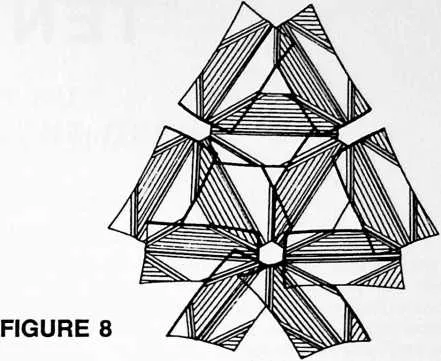 the openings where they come together, or additional sheets can be slipped in to shingle
over the openings.
the openings where they come together, or additional sheets can be slipped in to shingle
over the openings.
52 161
53 By laying out the three-way grid pattern so that the radial lines of the polygons are longer than the lines forming the sides of the bases of the polygons, we obtain the hexpent and tetrahedral forms of the multiple-sphere trussed constructions explained in the outline description of Figs. 5 to 8, inclusive q.v. Thus in Fig. 5 we have, in a four-frequency grid design, a typical hexagonal pyramid with its apex at the center of the icosa face RST, this pyramid being formed by three sheets, and the two induced triangles of each sheet making two sides of the pyramid. Pentagonal pyramids occur at each vertex of the icosa. The pattern is one comprising hexagonal and pentagonal pyramids the apexes of which define an outer sphere, and the comers of the bases of which define an inner sphere.
54 In Fig. 6, we again have a pattern of hexagonal and pentagonal pyramids, but here six sheets toe in to the apex of a hexagonal pyramid and five sheets toe in to the apex of a pentagonal pyramid. In both this view and Fig. 5, one of the induced struts extends the short way of the sheet and in this respect there is a similarity to the neutral, or one-sphere, form of Figs. 1--4.
55 In Fig. 7, the induced geodesic triangles of the sheets form an inverted tetrahedron at the center of the icosa face, and one of the induced struts of each sheet extends the long way of the sheet to form the common base of the two induced triangles. Each triangle is two frequency modules wide, one frequency module high.
56 In Fig. 8, we again have a pattern of hexagonal and pentagonal pyramids, six sheets toeing in to the apex of a hexagonal pyramid and five sheets toeing in to the apex of a pentagonal pyramid, and one of the induced struts extending the long way of the sheet.
57 The terms and expressions which I have employed are used in a descriptive and not a limiting sense, and I have no intention of excluding such equivalents of the invention described, or of portions thereof, as fall within the scope of the claims.