
6 DYMAXION DEPLOYMENT UNIT (SHEET) (1944)
2U.S. PATENT—2,343,764 53
3 APPLICATION—MARCH 21, 1941
SERIAL NO.—384,509
PATENTED—MARCH 7, 1944
4 FIGURE 1
8 FIGURE 2
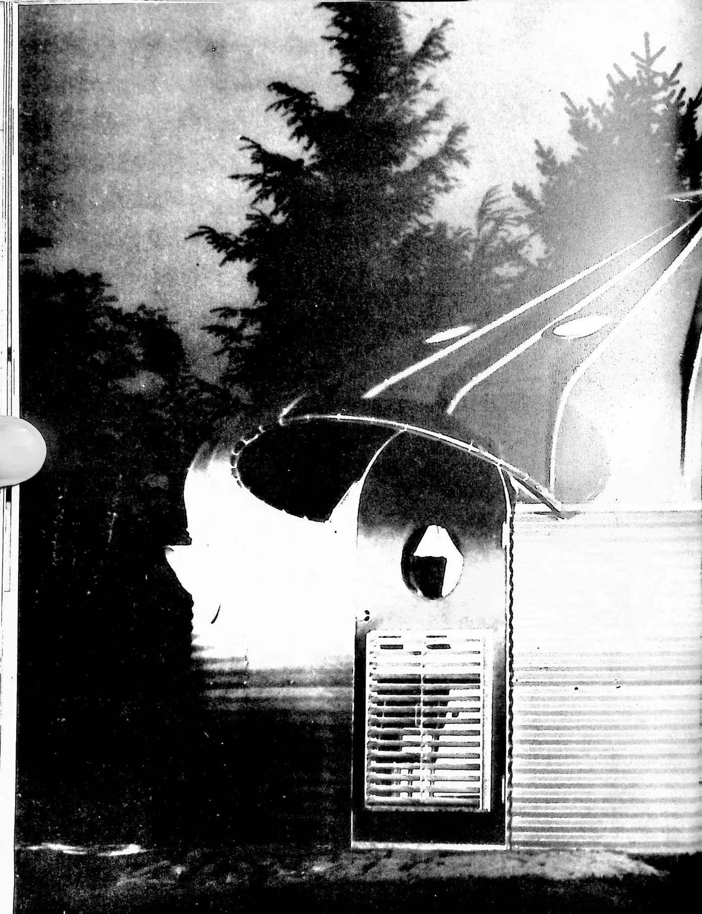
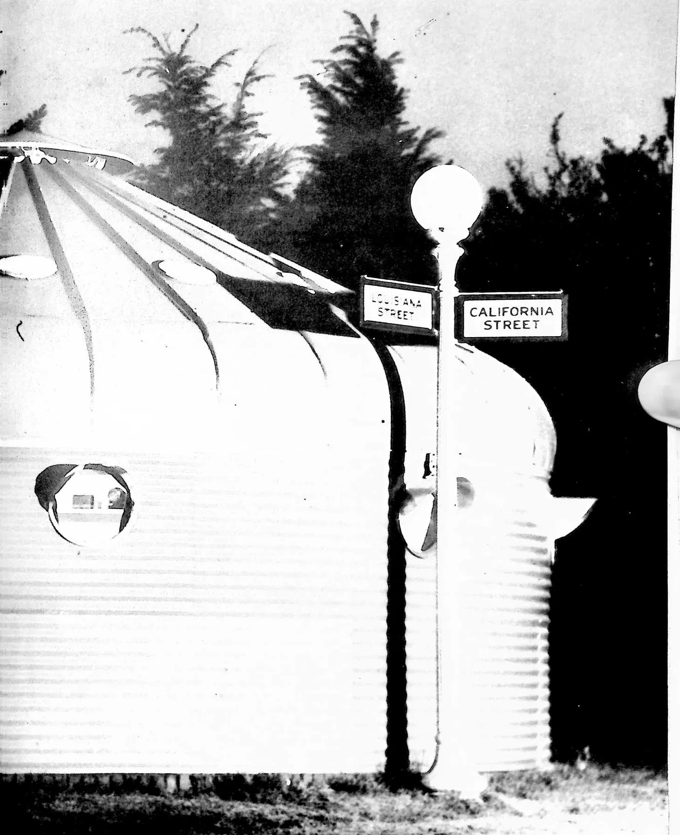
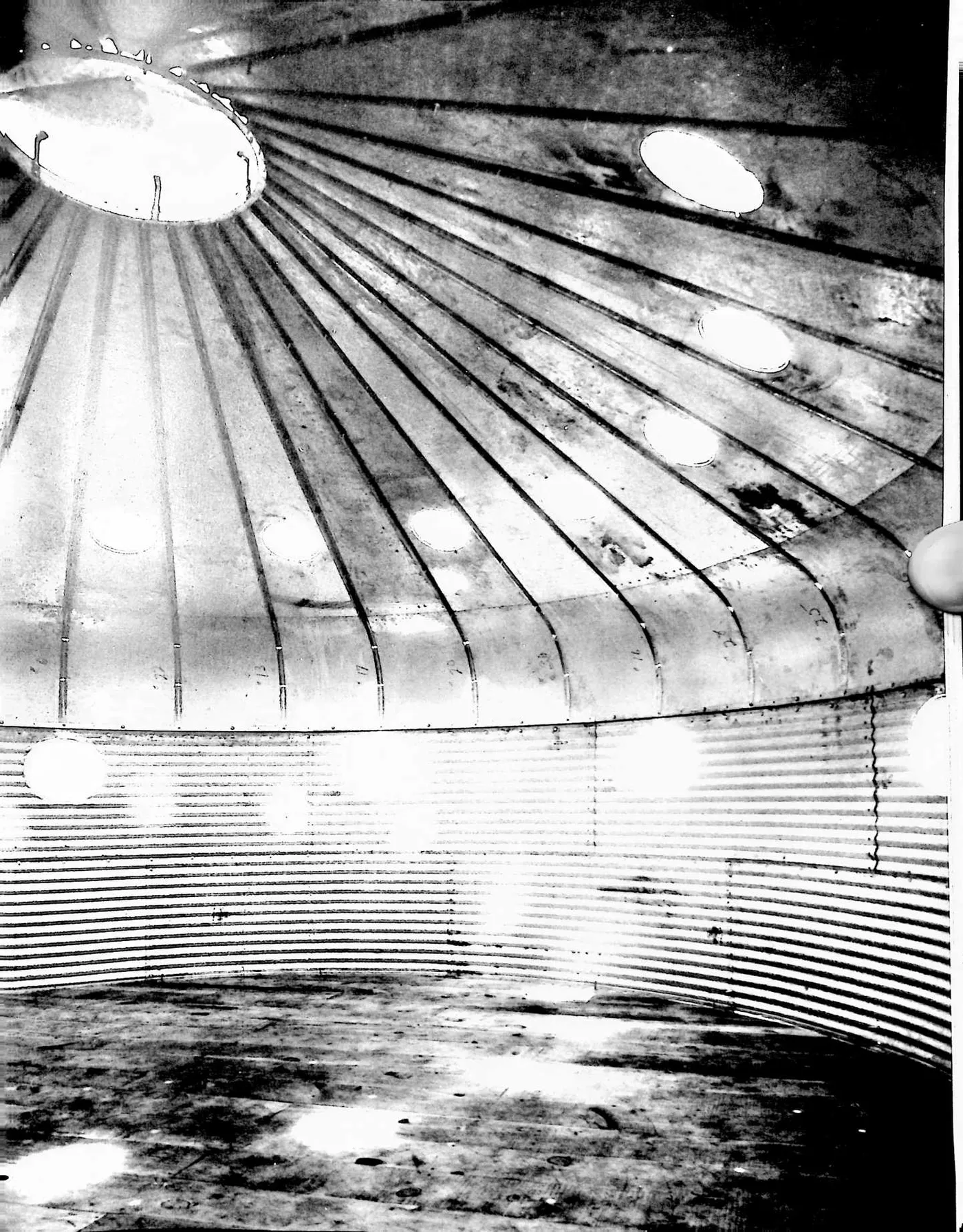
10 WHEN THE NEW DEAL SET ABOUT TO solve the problems of a paralyzed economy, amongst the greatest of these problems were those of the farmers. The U.S. Department of Agriculture developed a program entitled the Normal Grainery Program. This called for the grain producers to grow bumper crops and store their grain in galvanized corrugated sheet-steel grain bins with flat conical tops. The bins were of standard size. They were rodent-and rainproof. When a farmer had filled a grain bin, the local bank would seal the bin and pay the farmer for it at a fixed price. The government would then sell the grain wherever it found it expedient, so that the price paid to the farmer was not depressed by a national abundance. I found that these eighteen-foot-diameter mass-produced grain bins could be lined inside with fireproof insulation and could be floored with plywood. With windows and other modifications plus Sears Roebuck furnishings (kerosene flame icebox, stove, and other items) a bin could be turned into a humble but adequate dwelling unit.
11 At this time, 1940, World War II was clearly approaching. It was assumed by the British
12 that their major industrial cities would be bombed, and leading Scottish landowners offered their lands for the encampment of people from the bombed-out British cities. The Scottish government asked me to develop the Dymaxion Deployment Units with the converted grain bins. When the war broke out, the British found that the steel requirements of their armaments would have to take priority over their people’s livingry requirements, and the Dymaxion Deployment Unit orders of the Scots were canceled. The United States later bought the Deployment Units and installed them with air-conditioning units at the head of the Persian Gulf to house the American aircraft-ascending teams who delivered the ‘‘flyaway’’ U.S. aircraft to our then allies, the Russians.
13 UNITED STATES PATENT OFFICE
14 Richard Buckminster Fuller, New York, N. Y., assignor to The Dymaxion Company, Inc., Wilmington, Del., a corporation of Delaware
15 BUILDING CONSTRUCTION
16 This invention relates to prefabricated buildings, and more particularly to prefabricated shelter units capable of quick erection at low cost.
17 A considerable effort is being made and has been made in the past to develop a truly low cost housing unit that would be capable of mass production. Most of such housing units, however, have conformed more or less strictly to conventional architectural concepts of housing units, the principles of which have made it extremely difficult to produce prefabricated houses capable of rapid mass production and easy erection in a few hours time.
18 The problem is not simplified by the fact that such buildings must afford not only good protection against the weather, but should also provide comfortable as well as conveniently arranged living quarters.
19 One object of my invention is to provide a shelter unit or building having curved walls that answers these requirements and does not require the use of the ordinary internal framework or stress members.
20 A further object is the provision of a shelter unit of generally curved shape composed of a laminated shell, the different layers of which strengthen the other layers by reason of their manner of assembly and the curvature of the shell.
21 Another object is the provision of a shelter unit in which an outer curved shell of sheet material is strengthened and held more rigidly in place by sheets of resilient material sprung and held in the sprung position against the inside of the sheet material.
22 A further object of the invention is the provision of a novel floor structure for a building that is weather proof and capable of quick assembly at low cost from standard sheet materials.
23 Another object is the provision of a building having a curved side wall, a roof, and a curved eave portion connecting the roof and side wall that reinforces the entire structure.
24 A further object of the invention is the provision of low cost housing units capable of prefabrication on a large scale, quick assembly, and of being demountable for re-assembly at a different location.
26 14 14
27 FIGURE 4
29 Further objects of the invention are the provision of an adjustable ventilator system and movable partitions for such a shelter unit or building.
30 Other objects and advantages of the invention will be described and will be apparent from a description of the embodiments of my invention shown in the accompanying drawings, in which
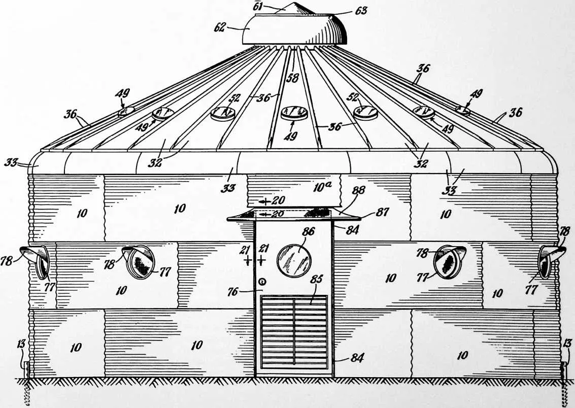
31 Figure 1 is a front elevation of a housing unit constructed in accordance with my invention.
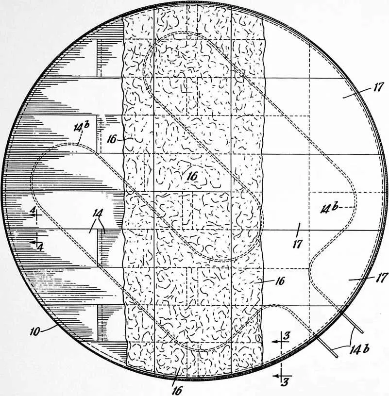
32 Figure 2 is a plan view partly broken away to show a built-up floor for such a housing unit.
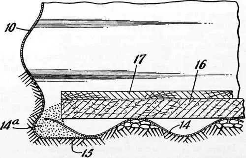
33 Figure 3 is a vertical sectional view on an enlarged scale of a detail, taken on the line 3--3 of Figure 2, to show the junction of the floor with the side wall.

35 58
36 FIGURE 5
37 FIGURE 6
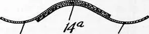
38 Figure 4 is a vertical sectional view of the base layer of the floor, taken on the line 4--4 of Figure 2.
39 Figure 5 is a fractional horizontal sectional view showing the laminated structure of the curved side walls.
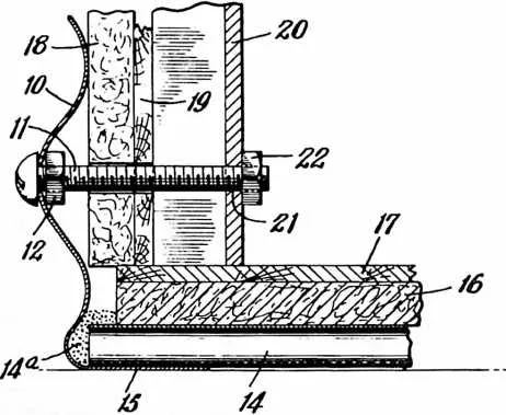
40 Figures 6, 7 and 8 are fractional vertical sectional views of the wall structure showing the bottom, intermediate and top of the side walls, respectively, said views being taken approximately on the line x—x of Figure 5.
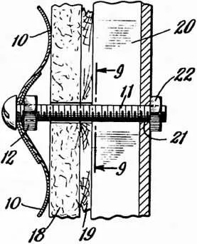
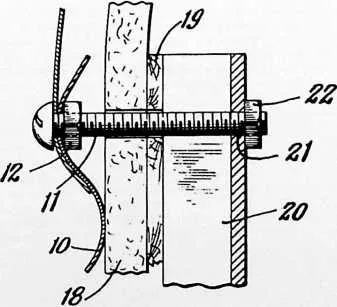
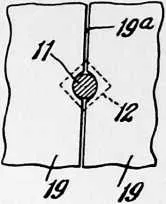
41 Figure 9 is a fractional vertical sectional view, taken on about the line 9--9 of Figure 5.
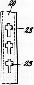
42 Figure 10 is an elevation of a section of a slotted channel bar that may be attached to the side walls as shown in Figures 5--8.
43 Figure 11 is a top plan view of a wall bracket that may be supported by the channel bar shown in Figure 10.
44 Figure 12 is a vertical sectional view showing a shelf supported by one of these brackets fixed in the slotted channel bar.
45 Figure 13 is a rear elevation of one of the brackets that may be used for supporting shelves, cabinets or other wall fixtures.
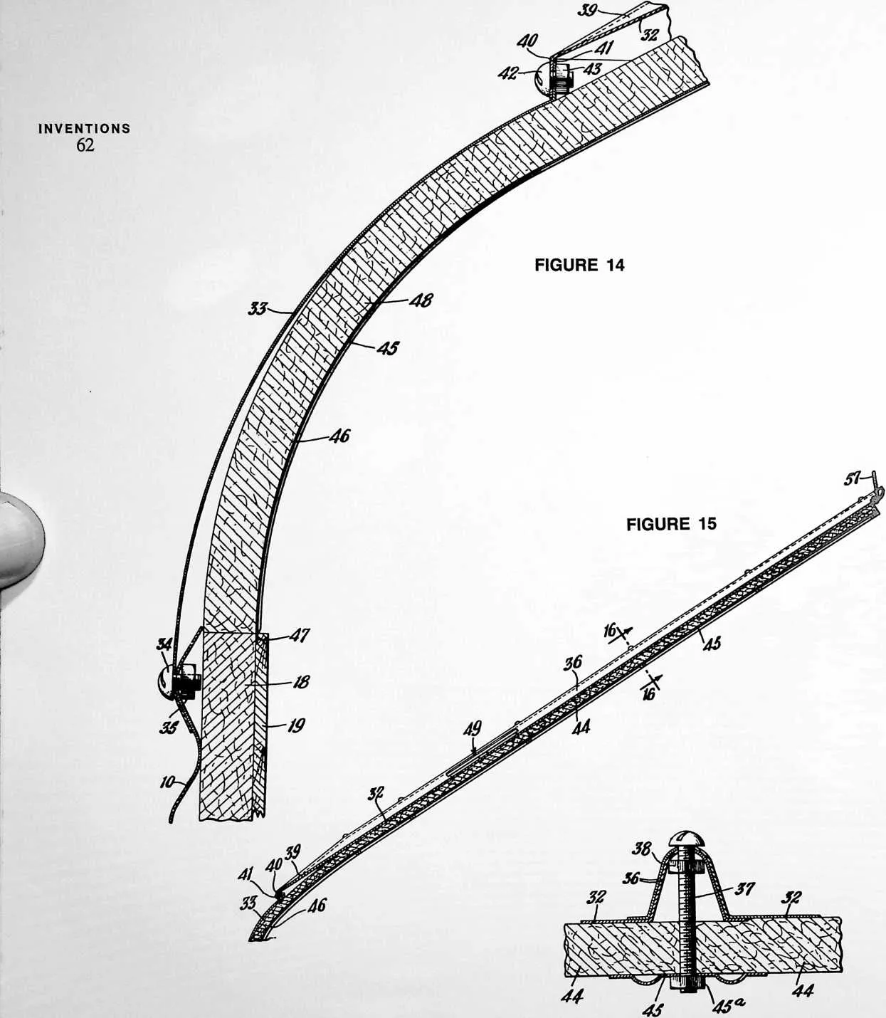
46 Figure 14 is a vertical sectional view through the eave portion of the building shell or wall.
47 Figure 15 is a vertical sectional view through approximately the center of one of the roof panels.
48 Figure 16 is a fractional sectional view, taken on the line 16--16 of Figure 15, to show the manner in which the roof panels and insulation are joined.
49 Figure 17 is a plan view of one of the roof panels.
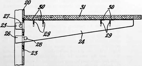
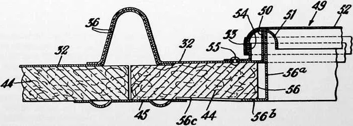
50 Figure 18 is a fractional sectional view through one of the roof panel apertures for light, taken on the line 18--18 of Figure 17.
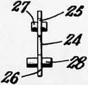
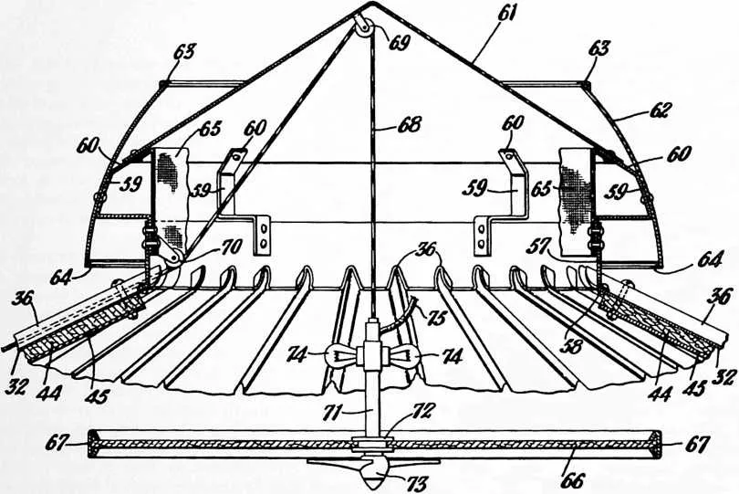
51 Figure 19 is a vertical sectional view through a centrally located ventilator at the top of the roof.
52 Figure 20 is a fractional vertical sectional view of a door frame, taken on the line 16--16 of Figure 1.
53 Figure 21 is a fractional horizontal sectional view of the door frame, taken on the line 17--17 of Figure 1.
54 Figure 22 is a horizontal sectional view through the building to illustrate one possible arrangement of partitions and furniture.
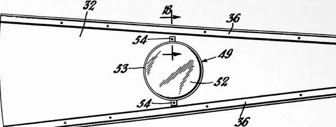
55 Figure 23 is a perspective of an end of a movable partition that may be used to divide the interior of the building into two or more rooms.
56 Figure 24 is a fractional elevational view of a modification of a building constructed according to my invention.
57 Figure 25 is a horizontal sectional view through the side wall of the building shown in Figure 24.
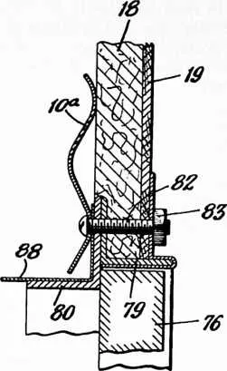
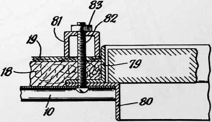
58 Figure 26 is a fractional vertical sectional view of the
60 FIGURE 7
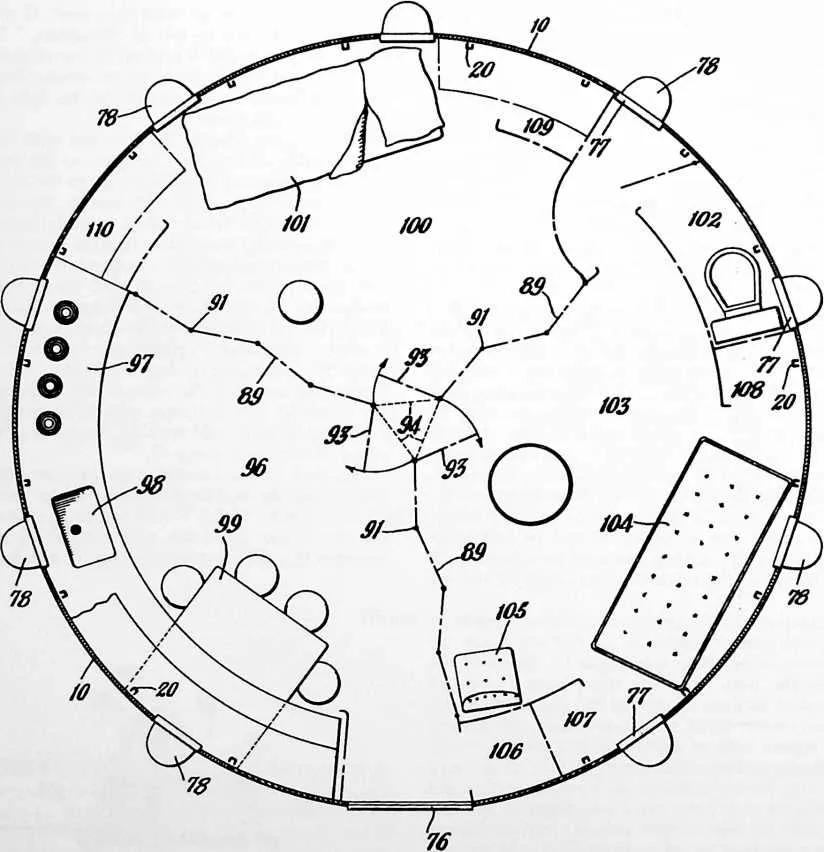
61 side wall, taken approximately on the line 26--26 of Figure 25.
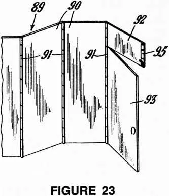
62 Figure 27 is a fractional vertical sectional view of the side wall, taken approximately on the line 27--27 of Figure 25.
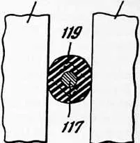
63 Figure 28 is a vertical sectional view of a detail of the wall structure, taken on the line 28--28 of Figure 26.
66 FIGURE 9
67 Figure 29 is a vertical sectional view through the eave and roof portion of the building shown in Figure 24.
68 Figure 30 is a plan view of a portion of one of the roof sections.
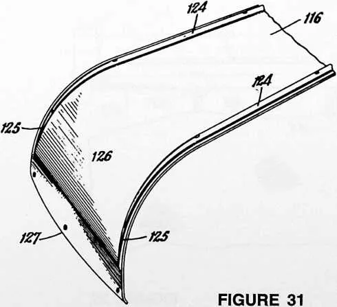
69 Figure 31 is a perspective view of the lower portion of one of the roof sections.
70 Figure 32 is a vertical sectional view through a modified ventilator for the building shown in Figure 24.
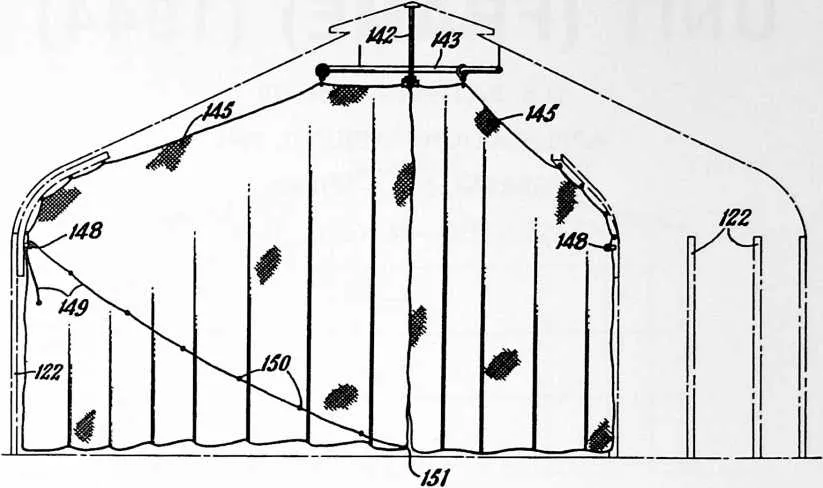
71 Figure 33 is a partially diagrammatic view of the interior of this building to illustrate a modified movable partition arrangement.
72 The embodiment of my invention illustrated in Figures 1 to 21 of the drawings is composed of a number of rectangular sheets 10 of suitable sheet material, such as a lightweight plain or corrugated galvanized steel or other metal, curved to form, when assembled, a substantially cylindrical shell. Three horizontal rows of such sheets are shown in Figure 1, although a smaller or larger number of rows may be used, and these sheets preferably overlap each other, with the uppermost sheet overlapping the sheet below it, and the vertical edges overlapping each other. The sheets 10 may be bolted together where they overlap by means of the bolts 11 and nuts 12 shown in Figures 5 to 8. A suitable anchoring means, such as the angle iron posts 13, may be driven into the ground around the lower edge of the lower row of sheets 10 and bolted to the sheets to hold them securely in place during and after erection of the unit. The sheets 10 are also preferably staggered with respect to the adjacent horizontal rows of sheets.
73 Referring now more particularly to Figures 2, 3 and 4, a concrete or other permanent type of flooring may be provided for the building, although a more portable form of flooring may be used consisting of a lower layer of sheet metal or other strong sheet material such as corrugated sheets of galvanized steel 14. These sheets may be generally rectangular in shape except for their outer edges which are curved to produce a generally circular floor, and the sheets 14 are preferably laid with their sides and ends overlapping each other. A suitable asphaltic mastic or other water-proofing material may be applied to these joints if desired. The sheets 14 may be laid directly on the ground or, if desired, a concrete or other suitable foundation may be provided for them.
74 The lower edges of the lower row of said sheets 10 are preferably bent inwardly at right angles to form the inwardly projecting flange 15 and the outer curved edges of

76 60
77 FIGURE 11
78 the base layer floor sheets 14 may be laid on top of this inwardly projecting flange and sealed with a suitable asphaltic mastic 14a or other suitable material.
79 On top of sheets 14 may be placed a layer of flat sheet material. This second layer may be composed, for example, of a number of rectangular sheets 16 of a suitable insulating board of more or less porous or solid construction, with these rectangular sheets extending in a general direction at right angles to the direction of the sheets 14. These sheets 16 may be laid with their edges abutting each other or, if desired, the edges may be grooved and overlapped. In order to provide as weatherproof a floor as possible, I prefer to coat, as by spraying
82 FIGURE 10
83 or dipping, the sheets 16 with a suitable asphaltum composition before they are laid in place.
84 A third layer may be applied on top of the sheets 16 composed of a plurality of rectangular sheets 17 of pressed wood, plywood or other suitable finishing material. These sheets 17 may be of generally rectangular shape, except for their curved outer edges, and laid in a general direction extending at right angles to the direction of the sheets 16 or, in other words, in the same general direction as the bottom layer of sheets 14. The sheets 16 and 17 may thus be arranged so that the joints of the different layers do not coincide in any portion of the floor.
85 This top layer of pressed wood, plywood or similar material may, if desired, be held in place by means of a suitable adhesive between the sheets 16 and 17, and if desired a water-proof paper, canvas or layer of similar material may be interposed between the sheets 16 and the sheets 17. This provides a floor with a suitable finish for direct use, although if desired it may be covered, of course, by linoleum or other suitable floor coverings.
86 The use of corrugated sheet metal for one layer of the floor furnishes a certain amount of resiliency to the floor, and, in addition, the sheets of metal are held more securely in place relative to each by reason of the corrugations. Such sheets are also easier to lay flat on the earth because the earth may be readily conformed to their under surface.
87 While the outer edges of the sheets 16 and 17 may extend into contact with the side sheets 10, it is preferable to leave a small clearance at this point to prevent subsequent buckling of the sheets 16 and 17 after the floor is laid.
88 Provision may also be made under the floor for heating by the use of a coil of pipe as shown in dotted lines at 14b
89 FIGURE 13
93 FIGURE 16
94 FIGURE 17
96 in Figure 2. Such a coil may be conveniently connected to the hot water supply so that hot water passes through the coil before reaching faucets or other outlets in the building. By placing such a heating coil under the metal floor sheets 14, the heat is uniformly distributed by the high conductivity of these sheets over the entire floor. If such a heating arrangement is employed, the various layers of the floor should not have too great an insulating effect but should be constructed of materials that will allow the heat to pass through into the room.
97 The side wall structure may be composed of the curved sheets 10 of suitable material such as corrugated galvanized sheet steel as described above, these sheets being held together where they overlap each other by means of the bolts 11 and the nuts 12. Suitable water-proofing or sealing means may be applied at these joints if desired.
98 The bolts 11 preferably project a substantial distance into the building, and when the sheets 10 are of generally rectangular shape and arranged in staggered fashion, additional inwardly projecting bolts may be affixed to the centers of these sheets to provide evenly spaced vertical rows of inwardly projecting bolts around the side walls.
99 Suitable insulating material in the shape of rectangular sheets, preferably of a height corresponding to the height of the vertical walls and of a width just allowing them to fit in a curved position between the vertical rows of inwardly projecting bolts 11, may now be applied inside the sheet metal walls. For example, sheets 18 of a suitable insulating material, preferably having some inherent resilience, may be provided with semi-circular notches along each side at points corresponding to the position of the inwardly extending bolts 11. The sheets are then held at the sides and the center portions of each sheet are pressed against the sheet metal wall to spring the sheets of insulating material into place. Natural resilience of the sheet insulating material will tend to press the side edges against the bolts 11.
100 By applying sheets of insulating material all around the interior of the side walls in this fashion, a structure is provided in which a curved wall of sheet insulating material is formed, held securely in place by its own resilience and stiffening the entire outer sheet metal wall.
101 Another layer comprising sheets 19 of plywood, pressed wood, or similar material may now be applied to the wall in a manner similar to the application of the sheet insulating material. In other words, sheets 19 of a height extending substantially the entire distance of the vertical wall and of a width allowing just sufficient tolerance to fit between the rows of bolts 11 in a curved position, may be similarly notched along their sides at points corresponding to the positions of the bolts 11, and sprung inwardly into place between the vertical rows of bolts. These sheets, referring to Figure 5, may be naturally flat as shown in dot-dash line, but when sprung into place
102 FIGURE 18
104 between the rows of bolts assume more or less of the curvature of the outer sheet metal wall made up of the sheets 10 and, of course, the similar curvature of the sheets 18 of insulating material.
105 The lower edges of the sheets 18 and 19 rest on the outer upper surface of the floor sheets 17, thus giving a finished appearance to the interior and assisting in maintaining a tight joint at the base of the side walls.
106 As shown in Figure 9, the notched edges of the sheet insulating material 18 and of the finish sheets 19 fit around the shanks of the bolts 11 so that the edges of the sheets 19 abut each other or practically meet, as may be thus cover the vertical seams 19a between the side edges of sheets 19 and, in addition, hold these edges securely in place against any accidental displacement.
107 Referring now to Figures 10, 11, 12 and 13, the channel sections 20 or other cover members may, if desired, be utilized to support shelves, cabinets and various other types of fixtures. For example, the faces of these channel strips 20 may be provided with a number of spaced keyhole or cross-shaped slots 23 and various fixtures may thus be secured in these slots. For example, wall brackets 24 may be utilized having a pair of rearwardly projecting ears 25, 26 with suitable pins 27, 28 pressed through
108 FIGURE 19
110 desired, presenting a smooth, pleasant finish to the walls inside disturbed only by the ends of the inwardly projecting bolts 11 and the vertical seams where these sheets come together. If desired, however, the sheets 18 and 19 may be sprung into place without notches in their sides, thus leaving wider seams between the sheets.
111 To cover the seams between the side wall sheets, vertical channel members 20, or other suitable cover members, having openings 21 to receive the ends of the bolts 11 may be fitted in place over the ends of the bolts 11 and held in place securely by the nuts 22. The nuts 22 may, if desired, be special round headed finish nuts that conceal entirely the ends of the bolts 11. These channel strips 20 openings in the brackets, or welded in place at right angles to the plane of the brackets 24.
112 By providing the pins 27 and 28 in a staggered position relative to each other as illustrated, the ears 25, 26 and the pin 27 may be inserted in two adjacent cross-shaped slots 23 of the channel member 20 and then allowed to drop down into a position in which the pin 27 presses outwardly against the inside of the channel strip 20 and the pin 28 is forced inwardly against the exterior thereof, thus holding the bracket 24 securely in place.
113 These brackets may be used for supporting shelves in a relatively fixed position. For example, the brackets 24 may be provided with narrow vertical notches 29 to re-
115 FIGURE 20
116 ceive the downwardly projecting portions of angle members 30 fixed to the lower surface of shelves 31. The shelves 31 may thus be secured in place, being rigidly supported and held against sliding movement toward or away from the wall structure.
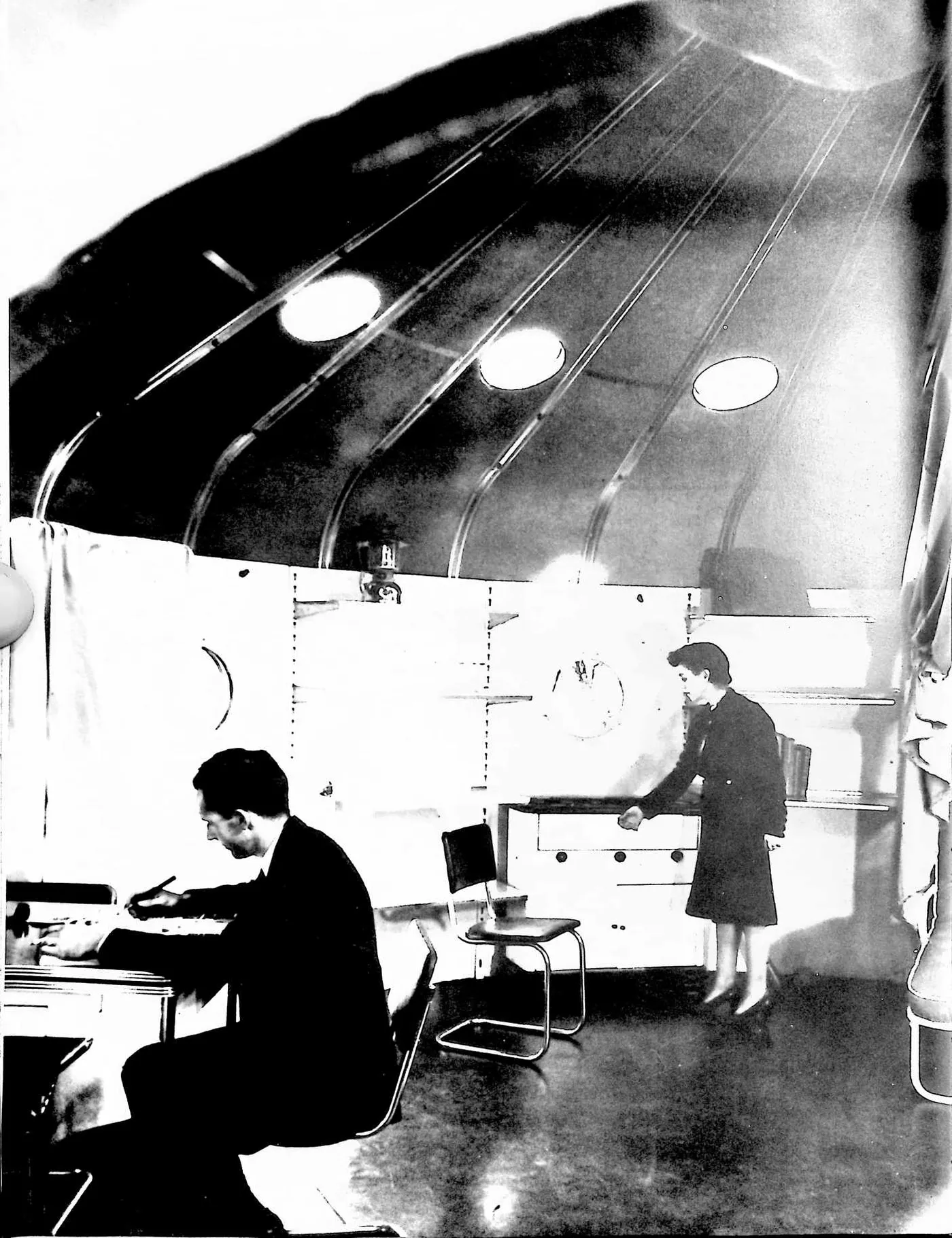
117 Referring now to Figures 14 to 18, inclusive, the roof of the housing unit may be composed of a number of pieshaped sections 32 of galvanized sheet steel or other strong sheet material, connected at their lower edges to the wall sheets 10 by means of the compound curved eave sheets 33. These eave sheets 33 may conveniently be made as single stampings of galvanized sheet steel or other material curved to conform to the general cylindrical shape of the sidewall sheets 10 and also curved inwardly about a horizontal axis toward the center of the structure. The sheets 33 may overlap the uppermost edges of the upper row of sheets 10 and be bolted together, with a suitable sealing material there between if desired, by means of the relatively short bolts 34 and the nuts 35.
118 The roof sections 32 are preferably formed along their side edges with raised ridges 36 so that they may be bolted together along these side edges by means of the bolts 37 and the nuts 38. Since these bolts 37 project through the roof sections 32 only at the top of the ridges 36, a relatively water-proof joint is provided, particularly if a sealing means such as asphaltum is applied between the overlapped portions. The lower portion of the roof sections 32 may have the ridges 36 tapered off to a flat surface, as shown at 39, and the lower edges of the roof sections 32 may be bent downwardly to provide flanges 40. The upper edges of the eave sheets 33 may be formed with corresponding flanges 41, so that these two flanges can be bolted together in overlapping position by means of the bolts 42 and nuts 43.
119 In order to insulate the roof, pie-shaped segments 44 of a suitable sheet insulating material may be utilized corresponding in shape and size to the individual roof sections 32 or to two or more of such sections when bolted together. The side edges of these sheets 44 of roof insulating material may be notched similar to the insulating sheets 18 to fit around the shanks of the inwardly projecting bolts 37, or if larger sheets 44 are used they may have holes to enable them to be pushed flat against the roof with the bolts 37 projecting through the sheets. These sheets 44 may be held in place by suitable cover strips 45 fitting over the ends of the bolts 37 and secured by the nuts 45a. The cover strips 45 preferably extend downwardly and are curved, as at 46, so that their lower edges fit in between the insulating sheets 18 and the finish sheets 19 of the side walls, as shown at 47. This provides a convenient means for holding the insulating material 48 in place inside the curved eave sheets 33.
120 In order to provide the interior of the building with sufficient light, a number of the roof sections 32, for example every alternate section, may be provided with a suitable skylight 49. A simple circular opening may be formed in these sheets 32 with the edges thereof bent outwardly to form a cylindrical flange 50. An annular channel frame 51 may be made to fit over the flange 50 and have stretched over its exterior a suitable transparent or translucent material, such as a sheet 52 of one of the transparent plastics known as ‘‘Celoglass.’’ The edge of this sheet of material is preferably curved down over the frame 51 and held in place by an annular band of metal 53 pressed on over the outside of the light transmitting material 52 and frame 51.
121 Angular tabs 54 may be provided with their vertical sides welded or otherwise secured to the frame 51, for removably securing these skylights to the roof by means of the rivets or bolts 55. If desired, the inside of the frame 51 may be filled with a suitable asphaltic waterproofing material before the skylight is secured in place.
122 The insulating sheets 44, of course, have suitable openings 56 cut out to coincide with these skylights, and frames may be applied to these openings inside the building to conceal the edges of the openings in sheets 44. For example, an annular frame may be formed with the flange 56a extending up into the frame 51 and with the flanges 56b covering the edges of the opening in insulating sheets 44. These frames may be simply pressed into place and rotated until the tabs 56c are caught under the edges of the cover strips 45.
123 The roof of the building may be provided at its top with a suitable ventilator. This ventilator may include a vertical cylindrical ring 57 notched along its lower edge so that the ridges 36 of the roof sections 32 may project therethrough. This cylindrical ring 57 may be secured to
125 the upper ends of the roof sections 32 by means of suitable bolts or rivets 58.
126 Projecting upwardly and outwardly from the ring 57 are a number of brackets 59 which have secured to their inwardly inclined upper ends 60 the lower edges of a one-piece conical sheet metal top 61. The outer edges of the brackets 59 may have secured thereto a curved cowling 62 extending a substantial distance above the lower edge of the conical top 61 and also extending down sufficiently far to protect the upper ends of the roof sections 32 from the weather. The cowling 62 may be strengthened by a suitable rigid circular frame 63 at its top and a similar circular frame 64 at its bottom. A space is thus provided between the lower edge of the conical sheet 61 and cowling 62, so that circulation of air, either upwardly or downwardly, may take place while rain or snow is intercepted by the conical top 61 and deflected to drop down on the roof sections 32 at a point below the upper edges.
127 Inside the ring 57 and extending between the ring and the conical member 61 is a cylindrical screen 65 which may be used to keep out insects.
128 With such a ventilator, it is desirable to provide special means for controlling the circulation of air. To prevent too strong a draft upwardly or downwardly through the ventilator, a circular sheet of solid material, such as plywood, pressed wood, or a suitable transparent or translucent material, forming a valve 66 may be held in the circular frame 67 and suspended by means of a cable 68 from the top of the conical ventilator top 61. For example, the cable 68 may pass over a pulley 69 affixed near the undersurface of the conical ventilator member 61, and another pulley 70 may be provided to lead the cable down to a point where it can be grasped by a person inside the building to raise or lower the valve 66.

131 Raising or lowering this ventilator valve, of course, controls the amount of air that is allowed to flow in or out through the ventilator.
132 If desired, one end of cable 68 may be attached to a frame 71 having a suitable collar arrangement 72 for attachment to valve 66. An electric fan 73 may thus be supported directly below the valve 66. Suitable lights 74 may also be provided in this suspension, if desired, to furnish
133 indirect lighting or a direct lighting if the valve 66 is made of transparent or translucent material. Current for the fan and lights may be supplied through a flexible cable 75 from any suitable source (not shown).
134 The housing unit may also be provided with a suitable door 76 and a number of windows 77 in the side. Because
137 of the curvature of the side wall, it is convenient to make the windows 77 circular in shape. For this purpose, the middle row of sheets 10 may have openings and flanges formed in them in a manner similar to the roof sections 32 that are provided with skylights. Suitable window frames may be mounted in these openings and provided, if desired, with external shields 78. Suitably fixed or removable screens may be fitted into the frames, and windows arranged for opening may be provided. The shields 78 aid in rendering the windows tight and proof against framework to receive the door 76, which is hinged in the usual manner at one side as shown at 84 (Fig. 1). If desired, the door may be provided with adjustable louvres 85 for ventilation without opening the door, and a suitable window 86.
138 It may also be desirable to provide a canopy for the door which may be supported by a partially circular frame 87 having its ends suitably secured to the vertical walls of the building above the door frame. A layer of canvas, sheet metal or other suitable material 88 may be secured to the frame 87 around its periphery and secured to the wall of the building, preferably inside and under the lower edge of the sheet 10a just above the door frame.
139 Referring more particularly to Figures 22 and 23, the interior of the building may be divided into a number of rooms by means of movable partitions 89, three of which are illustrated. These movable partitions may, if desired, be affixed at one end directly to the channel bars 20 by
140 121 121
142 FIGURE 28
144 FIGURE 27
145 the weather, and at the same time serve as wind scoops when the windows are open to catch the cooler air rising outside the building so that it will be drawn in and then carried up through the ventilator.
146 A suitable door frame may be formed by the angle bars 79 and 80 bolted around the top, bottom and sides of the door opening to the edges of the sheets 10 by means of the bolts 82 and nuts 83. At the sides of the door frame, channel bars 81 lining the inside of the door may also be held in place by the bolts 82 and nuts 83. This provides a means of brackets similar to the brackets 24. The partitions may comprise rectangular sheets 90 of plywood or pressed wood hinged together as at 91.
147 The free ends of the partitions can be formed with small upper sections 92 and lower sections 93 in the nature of doors, both hinged to the same sheet 90. Thus, when these three partitions are all extended to the center of the building, the three upper sections 92 may be connected together, as shown in dotted lines 94 in Figure 22, to form a triangle in the center of the building. Suitable sliding bolts 95 and corresponding sockets may be provided for this purpose.
148 A small triangular hallway is thus furnished, with doors from each of the three rooms thus formed leading into this small hallway. This provides a convenient way of passing from any one room to either of the other two rooms.
149 Various interior arrangements may be employed, and the building is well adapted for other uses than as a dwelling. In the layout shown in Figure 22, however, the room 96 is a kitchen with a stove or electric burners at 97, a suitable sink at 98, and a table and chair arrangement at 99. These fixtures may be readily attached to the channel bars 20 and supported thereby. The room 100 is arranged as a bedroom with a suitable day bed or cot 101, which may be converted to a couch in the day time. A lavatory is shown at 102, which may utilize a chemical hopper or be provided with suitable plumbing as is expe-
150 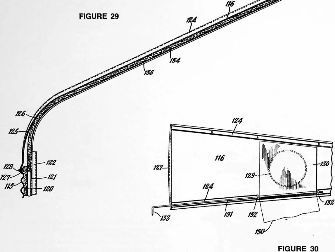 dient. The living room 103 may be fitted with a suitable divan 104 and chair 105. If
desired, the partitions may be so arranged that convenient closets are formed at 106, 107, 108,
109 and 110.
dient. The living room 103 may be fitted with a suitable divan 104 and chair 105. If
desired, the partitions may be so arranged that convenient closets are formed at 106, 107, 108,
109 and 110.
151 It will be apparent that the external sheets 10 forming the outer shell of the building will be cut out to provide suitable openings for the windows and door. Similarly, the sheet insulating material 18 and the internal finish sheets 19 may be cut out to provide for the door and windows.
152 In erecting a building of the construction illustrated, it may be desirable to make a shallow excavation although, if the ground is reasonably level, no excavation at all may be needed. The lower tier of sheets 10 is first assembled, being secured together at their ends and held in place by suitable anchoring means such as the posts 13. The floor can then be laid directly on the ground or on any suitable foundation by simply laying the different layers of sheets 14, 16, and 17, and applying asphaltic or other sealing material to the joints as needed.
153 While the floor is being laid, or thereafter, the second and third tiers of sheets 10 and the eave sheets 33 may be assembled. The roof sections or sheets 32 are next bolted in place, and for this operation it is desirable to provide some temporary support for the inner ends of the roof sections 32 while their outer edges are being secured and before the ventilator is assembled.
154 This temporary support may be easily made by bolting together inside the house a scaffolding composed of the channel bars 20. These bars are provided with numerous holes for bolts and are sufficiently strong to support the weight of the center of the roof. After the ventilator has been assembled in place, this scaffolding may be taken down and the channel bars 20 used for holding the side wall sheets 18 and 19 in place.
155 A building constructed in accordance with my invention may be used as a dwelling, but is also well suited for other uses. For example, a building 20 feet in diameter would have about 60 feet of wall space for shelves if the building is used for a store. Various other uses include schools, churches, wayside establishments, camps, boathouses, etc.
156 The building is also easily adapted to military use, because it may readily be surrounded by a suitable wall of concrete poured after the building is partially or completely erected and using the building wall as a part of the form.
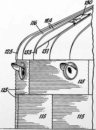
157 Another modification of my invention is illustrated in Figures 24 to 33, inclusive, in which numeral 115 indicates side wall sheets similar to the sheets 10 forming an external layer of the side walls of the building. In this case, however, the lower edges of the combined roof and eave sheets or sections 116 are directly attached to the upper edges of the upper row of sheets 115. Two horizontal rows of the side wall sheets 115 are illustrated, although a single row of such sheets or any suitable number of rows may be employed, as desired. These sheets are preferably made of a relatively strong material, such as a galvanized sheet steel, and may have horizontal corrugations for reinforcement. The sheets preferably overlap and are sealed at their joints with a suitable water-proof material such as an asphaltic mastic, as described in connection with the building shown in Figure 1.
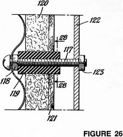
158 The side sheets 115 are also preferably bolted together in the position illustrated in Figure 24 to form an outer shell for the house. Bolts 117 holding these sheets 115 together may be secured in place by means of the nuts 118, leaving a substantial length of the bolt shanks projecting inwardly from the sheets 115. To support the inner layers of the side walls and permit easy installation of these inner layers after the outer shell of the house has been erected, collars 119 of suitable resilient material, such as rubber, may be slipped over the protruding shanks of the bolts 117. Vertical rows of rubber coated
160 bolts are thus provided extending into the interior of the building between which the insulating sheets 120 and the sheets 121 of suitable finishing material may be fitted.
161 For example, the sheeting insulating material in the form of rectangular sheets 120 may be simply sprung into place and forced in between the rows of bolts 117 carrying the collars 119. The edges of the sheets 120 may be notched, if desired, to fit around the collars 119, although notching is not necessary to obtain a good fit of the sheets 120 with the extra tolerances provided by the resilient collars 119. The sheets of finishing material 121, such as plywood, pressed wood or other suitable material, may be similarly sprung into place but are illustrated as sprung only to a slight degree instead of lying substantially flat against the insulating sheets 120.
162 In this manner, the resiliency of the sheets 120 and 121, whether they are sprung completely or partially, exerts a pressure against the sides of the bolts 117 with a resultant outward pressure on the outer shell composed of the sheets 115 that serves to increase the rigidity and strengthen this outer shell. In addition, of course, this stressed condition serves to hold the sheets 120 and 121 securely in place even if shrinkage or swelling of the sheets 120 and 121 takes place.
163 To cover up vertical seams between these side wall sheets, suitable channel members 122 similar to the channel members 20, or other vertical extending cover members, may be fitted over the ends of the bolts 117 and secured in place by means of the nuts 123.
164 The roof sections 116 can be formed from single sheets of suitable material, such as galvanized sheet steel, with raised ridges 124 along the side edges of these pie-shaped segments, tapering off to a flat sheet near the lower edges of the sections, as indicated at 125. The lower portions of these roof sections or sheets are preferably curved, as illustrated at 126, about a substantially straight horizontal axis to form the building eaves. The lower edges of the sections 116 may terminate at the lower end of this curve or be curved down in a section as shown at 127 that is not curved about a horizontal axis. In either case, this lower edge should be curved about a vertical axis to conform to the curvature of the sheets 115. Thus, the lower portions of the roof sections 116 are either formed with a definite compound curve or are curved first in one direction and then in another to produce substantially the same effect. This compound curve arrangement at the eaves serves to stiffen and strengthen the side wall sheets 115, and also simplifies the erection of the building, providing an external construction of pleasing effect with fewer horizontal seams or joints.
165 A suitable number of roof sections 116 are secured at their lower edges in overlapping position to the upper edge of the sheets 115 by means of suitable bolts 128, and these individual roof sections 116 are bolted together along their sides with the ridges 124 overlapping, as previously described. Suitable asphaltic water-proof material may be used to seal these joints, if desired, and skylights 129 may be provided in the roof sections, as previously mentioned.
166 Under some conditions, it may be desirable to blackout the interior of the building or shut off the passage of light through one or more of the skylights 129. One convenient way of accomplishing this is to provide cover plates 130 fastened to rods 131 extending along the tops of the ridges 124 and passing through the eye-bolts 132. These rods may extend down to the eave of the house and be formed at their ends with suitable handles 133 to enable a person standing outside the house to rotate the cover plates 130 from a position covering the skylights 129 to a position in which the cover plates 130 lie flat on
167 the next roof section 116, as shown in dot-dash lines in Figure 30.
168 Suitable insulating material may be provided underneath the roof sections 116, as illustrated at 134. This insulating material may be held in place by cover strips 135 bolted to the roof sections 116 and overlapping the edges of adjacent insulating sheets 134, as previously described.
169 The insulating sheets 134 may extend downwardly inside the curved eave portion of the roof sections 116 and abut the upper edges of the vertical insulating sheets 120. If a relatively compressible sheet insulating material is employed, however, these roof insulating sheets 134 may extend down far enough to overlap with the vertical sheets 120, and these sheets 120 and 134 where they overlap are simply compressed together at the points where necessary between the outside sheets 115 and the sheets 121 of finishing material.
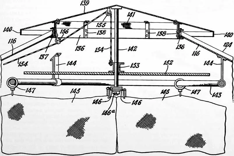
170 Referring now to Figure 32, the upper ends of the roof sections 116 may project into an outwardly facing annular channel bar 136. Suitable sealing means, such as asphaltic material 137, may be applied around the channel of this annular bar or ring to make a water tight construction. A number of brackets 138 may be bolted to the annular bar 136 to support at their upper ends a conical ventilator top 139. This conical top preferably has a downwardly extending flange 140 around its outer edge. A suitable cylindrical screen 141 may be provided between the upper edge of the annular channel bar 136 and the lower surface of the conical top 139.
171 Suspended from the top of the conical piece 139 is a rod 142, and an annular ring 143 surrounding this rod may be suspended from the roof by means of brackets 144 bolted to the roof sections 116. This provides a simple support for movable fabric partitions 145 (Figures 32 and 33). Each of these fabric partitions or curtains may be supported at their inner end by a ring 146 supported for rotation about the rod 142 by means of the nut and washer 146a. A second ring 147 may be provided to slide around on the ring 143 through an angle of approximately 120° between two of the brackets 144.
172 At the side walls, the curtains 145 may be supported by suitable pulleys 148 removably attached to one of the vertical channel bars 122. These pulleys also carry a suitable cord 149 running through a number of rings or loops 150 sewed or otherwise secured on the curtains 145 and extending down to the lower central corners 151 of the curtains where the ends of these cords are attached to the curtains.
173 The curtain partitions 145 may thus be drawn back into a draped position by simply pulling the cords 149 until the curtains lie along the inside of the roof and against the side wall of the building. The pulleys 148 may be moved around and attached to any suitable channel bar 122 to divide the room up into different sizes of rooms as may be required.
174 A valve or ventilator regulator 152 may be provided underneath the conical ventilator top 139 with a collar 153 arranged to slide up and down on the rod 142. This regulator or valve 152 may be raised or lowered by means of a suitable cable or cord 154 running over the pulleys 155 and 156 and extending down to the side wall within reach of a person in the building. This form of sliding ventilator regulator is simple to adjust and is not readily tipped or otherwise moved out of place by sudden up or down drafts through the ventilator.
175 Various other modifications of my invention will be readily apparent to those skilled in the art.
176 A particular advantage of a building shaped like the
178 FIGURE 33
179 73
181 embodiment shown in the drawings is the marked efficiency in heating. By reason of its shape, wind currents do not burble but flow smoothly around the outside of the building and do not carry away as much heat by convection as is carried away from the ordinary building of angular shape. In addition, the heating system may be centrally located so that the heat is uniformly distributed throughout the building interior.
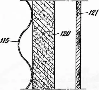
182 The construction illustrated and described also provides a building that can be readily taken apart and moved to a new location without substantial loss of materials. At the same time, the use of curved wall segments makes this possible using relatively light weight construction materials.
183 The construction and shape of the building lends itself to the use of many duplicate parts that nest together and may be packed into a relatively small space for shipment.
184 The terms and expressions which I have employed are used as terms of description and not of limitation, and I have no intention, in the use of such terms and expressions, of excluding any equivalents of the features shown and described or portions thereof, but recognize that various modifications are possible within the scope of the invention claimed.