
15 From Geodesic to Tensegrity: The Invisible Made Visible
2"A geodesic is the most economical relationship between any two events" (702.01).
3 Fuller's definition immediately calls to mind great circles, which provide the shortest routes between two events on a spherical system.
4 Actually, clarifies Fuller, the general case of "most economical relationship" is necessarily a great circle.
5 "It is a special case in geodesics which finds that a seemingly straight line is the shortest distance between any two points in a plane."
6 In other words, a given area may be such a small portion of a spherical system that it appears flat; however, because all identifiable experiences belong to systems, "great-circle segment" and "geodesic" are interchangeable in synergetics.
7 Already familiar with the theory of great circles and their polyhedral symmetries, we can apply theory to practice. A little experimentation uncovers two important discoveries, demonstrating again why the discipline of building models was essential to Fuller's mathematical exploration.
8 The first discovery is easily visualized without actually building a model. Imagine a metal sphere and a wire ring just large enough to fit around the widest girth of the sphere. This circular ring qualifies as a great circle and therefore can delineate the shortest route between any two points on the sphere. However, there is a practical problem; the ring slides off the sphere. It may seem like a strange observation, but Fuller tended to investigate unusual aspects of his subject matter, and frequently such seemingly whimsical sidetracks have proved fruitful.
9 Bring in a second wire circle of the same diameter. As we recall from the last chapter, a pair of great circles intersect at two points 180° apart. To keep the two wire loops on the sphere, they are tied together at both crossing points. The effort fails, for the two circles are free to spin around their common axis, and as soon as they line up both circles slide off the sphere together. Try again. A third great circle is placed anywhere on the sphere except through [232/233]the intersection of the other two. Whether arranged randomly or symmetrically (as a spherical octahedron), when intersections are tied together all three circles are immobilized. Triangulation creates a stable cage.
10 "Not until we have three noncommonly polarized, great-circle bands providing ornnitriangulation…do we have the great circles acting structurally to self-interstabilize…" (706.20).
11 Three differently oriented great circles is the minimum for a stable model. The discovery may seem trivial at first, but we have no indication from design that the stability of a "3-way grid" is widely understood in our culture. On the other hand, Southeast Asians have utilized this principle for thousands of years. Fuller points out that a vital need for strong baskets led them long ago to discover that a triangulated weave stays rigidly in place, whereas the 2-way weave used by other cultures is easily distorted.46
12 Southeast Asian children today still play with a reed sphere consisting of six interwoven great circles—perhaps the oldest known toy (Fig. 15-125). Characterized by icosahedral symmetry, the ancient design utilizes the inherent stability of a 3-way grid to make a lightweight and virtually indestructible ball out of delicate reeds. A modern toy has yet to improve upon its simplicity and durability.
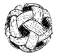
14 Fig. 15 125 Reed sphere of six interwoven great circles
15 The second discovery, which should be experienced to be fully appreciated, will nevertheless not come as a surprise at this point. Experimenting with wire models, Fuller found that the more great circles, the stronger the sphere. That much is self-evident, but the degree to which their strength increased far exceeded his expectations. This was not the kind of linear relationship exhibited by ordinary structures; rather the increasing rigidity of his great-circle models (from the minimum 3 to the icosahedral 31) could only be called synergetic.
16 We skip directly to the strongest model, provided by last chapter's limit case, 31 great circles. Triangulated geodesic arcs produce an [233/234]extremely sturdy, lightweight enclosure out of thin wire. Let's look closely at the pattern; our study is made considerably less complicated by isolating the LCD as described in the preceding chapter. Accordingly, we study only one of the 120 triangles framed by the icosahedron's 15 great circles, and observe that it is asymmetrically subdivided by the 6- and 12-great-circle patterns (Fig. 15-126). Notice the variations in arc length and surface angle—made more obvious by viewing this small region out of context. The overall 3-way grid incorporates longer and shorter arcs, thereby subdividing the sphere's surface into triangles of very different shape and size.
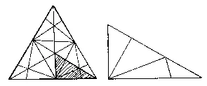
18 Fig. 15 126 31-great circle subdivision of icosahedron LCD
19 The LCD of the icosahedron is asymmetrically subdivided by the 31 great-circle pattern.
20 The load distribution and resulting strength of these wire models is a function of symmetry; the longer the arc, the more vulnerable it is to stress.
21 A question of balance—number, length, number of lengths:
This question was demonstrated in the "tensegrity" bicycle wheel experiment mentioned in
Chapter 7 Vector Equilibrium. In tests to determine the minimum number of tension (Dacron
string) "spokes" required to stabilize its hub, the wheel's eventual structural failure originated
with buckling of its rim. Long arc spans (which were a consequence of the low number of radial
spokes) were too thin to withstand the compression force created by loading the hub and
transmitted to the rim through the tension spokes. The usual arrangement, which
consists of a fairly large number of spokes (36 or more), therefore turns out to be
advantageous; despite the fact that there are many more spokes than necessary to
restrain the hub, this large number does serve to subdivide the otherwise vulnerable arc
segments of the compression-element rim. See also Edmondson, "The Minimal Tensegrity
Wheel".
22 It is clear that the most advantageous system would have all arcs as close to the same length as possible, but how can we improve upon the symmetry of the 31-circle pattern?
23 A second problem with the arrangement is that as a limit case, it does not present a logical course for further subdivision. To build progressively larger models with sufficient strength, we must find a way to generate more and more great-circle segments, or "higher frequency" in synergetics terminology. Both problems are solved by Fuller's next step.
24 To explore other methods of developing large multifaceted enclosures, we go back to the system that already has the greatest number of equivalent regular faces, the icosahedron. A 3-way grid of evenly spaced lines (imagine a triangular checkerboard) divides the icosahedron's equilateral triangles into as many smaller triangles as desired (Fig. 15-127).
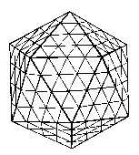
26 Fig. 15 127 4-frequency (4v) triangles superimposed on icosahedron
27 However, this subdivision does not yet lead to an effective design strategy, for if neighboring triangles of a structural system lie in the same plane, the enclosure will deflect in and out, like a trampoline, in reaction to an applied load. Unless vertices are reinforced using rigid joints—in which case, the system [234/235]is functionally equivalent to the original icosahedron—the advantages of triangulation are lost. It is thus clear that a convex polyhedral enclosure with more than twenty triangles cannot consist exclusively of equilateral faces. Adjacent triangles must differ slightly in shape and size to allow angles around each 6-valent vertex to add up to less than 360°, as necessary for continuous convexity.47 Fortunately, this unavoidable variation among chord lengths can be far less than that of the 31-great-circle pattern. To understand how these irregular triangles are generated, we back up and review the problem as a whole.
Theory Behind Geodesic Structures: Summary
29We can think of Fuller's task as a mathematical game confined to the rules of synergetics, in which the goal is to enclose as much volume as possible with the least amount of material. A solution must combine two geometric principles—integrating overall shape considerations with the requirements for local stability. Geometry tells us that the shape with the greatest volume/surface-area ratio is a sphere; synergetics challenges that sphere to materialize.
30 "Since physics has found no continuums, we have had to clear up what we mean by a sphere." (1023.11)
31 This game calls for a solution we can actually build and touch, which means the best structural approximation of that elusive sphere.
32 We thus have redefined the problem in terms of "operational mathematics". To get started, we might experiment with toothpicks, thus limiting the game to enclosures with identical struts. This brings [235/236]us back to Fuller's "three prime structural systems in Universe"—the inventory of self-stabilizing systems with equal vectors. Of the three—tetrahedron, octahedron, and icosahedron—the third has the most volume per toothpick (Chapter 5). An icosahedron is thus the best we can do with toothpicks, but of course it is not a satisfactory solution.
33 How can the enclosure become more spherical and still be stable? The geometric logic continues: through systematic symmetrical subdivision of our best approximation—taking full advantage of the stability of triangles. It hardly needs to be restated:
34 "If we want to have a structure, we have to have triangles" (610.12)
35 In short, two simple principles taken together lead to a solution to the stated problem. Combine the advantageous shape of the icosahedron with the stability of triangles, and the geodesic dome almost materializes. The logic is as exquisite as it is simple.
36 But we're missing a step. How can we develop the "checkerboard" tessellation illustrated above into a functional structure? The icosahedral edges can be divided into any number of segments. The greater the number, or "frequency", the more spherelike the end result will be. Then, to complete the transformation, each new vertex (superimposed on icosahedron faces) must be projected out to the surface of the imaginary sphere defined by the icosahedral vertices—and then interconnected by great-circle chords (Fig. 15-128). The nature of this projection accounts for the slight variation in [236/237]shape and size of triangles; the farther away a chord is from an icosahedral vertex, the more it is stretched during the transformation from planar to spherical.
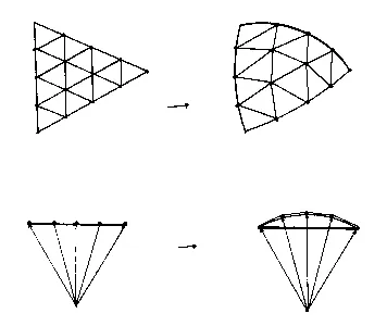
38 Fig. 15 128 Transformation from planar to spherical
39 Each new vertex is projected outward to the surface of an imaginary sphere defined by the original icosahedron vertices.
40 The resulting omnitriangulated polyhedron has six triangles at every vertex except for those located at the twelve vertices of the original icosahedron, which continue to join five triangles (Fig. 15-129).
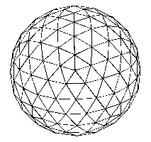
42 Fig. 15 129 4v icosahedron: transformation of Fig. 15-3
43 The system can have indefinitely many 6-valent nodes, but the existence of exactly twelve 5-valent vertices is a prerequisite to closure. Happily, there is also a considerable engineering advantage in having five or six struts leading out from each vertex: forces are instantly distributed in many directions—omniradially, Bucky might say—producing structures with unprecedented strength in relation to their weight.
44 This is the basic strategy behind the geodesic dome.
Geodesic Design in Nature
46Fuller points out that an extremely high-frequency geodesic polyhedron provides the true model of physical systems which we interpret as spheres, as for example a soap bubble. The notion of a continuous surface equidistant from a central point is scientifically [237/238] unacceptable, that is, inconsistent with physical reality; on some level of resolution all "spheres" consist of discrete quanta—untold numbers of energy events interconnected by an even greater number of vector-relationships, or forces. He has clarified this particular misconception countless times:
47 535.11 Because spherical sensations are produced by polyhedral arrays of interferences identified as points approximately equidistant from a point at the approximate center, and because the mass-attractive or—repulsive relationships of all points with all others are most economically shown by chords and not arcs, the spherical array of points produces…very-high-frequency, omnitriangulated geodesic structures…
48 Our eyes cannot see individual molecules in the delicate transparent soap bubble, nor can we detect the chordal chemical attractions between molecules. Nevertheless they exist, explains Fuller, and it is our responsibility to understand and teach the truth about Universe. Once again, his goal is to provide tangible models of otherwise invisible phenomena.
49 Of all possible solutions, a high-frequency triangulated shell with icosahedral symmetry provides the most efficient method of enclosing space with a minimum of material and effort. Accordingly, nature relies on this elegant design in many situations calling for protective enclosures, regardless of scale. Examples include the small sea creatures called Radiolaria, the fibrous web of the eye's cornea, and the protein shell of many viruses.48 We looked into the structure of spherical viruses in Chapter 8 and can now go into greater detail based on our increased familiarity with geodesic theory.
50 The design problem is familiar by now: tiny amounts of genetic material must be protected by a tough protein shell. As nature is scrupulously efficient, the choice is clear. A "spherical" distribution of protein molecules will satisfy the basic criteria in terms of conserving material relative to volume, while icosahedral symmetry will provide the most even distribution. The natural balance sought by chemical forces leads to approximately equivalent spans, which is geometrically accomplished by high-frequency icosahedral systems. In short, the structure of viruses is a product of nature's eternal tendency toward equilibrium. Geometry imposes the rules.
51 Reassuringly, observations (with the electron microscope) of isometric virus shells have consistently revealed icosahedral designs. Dr. Aaron Klug, who first observed the geodesic structuring of viruses, wrote to Fuller in 1962 telling him of this discovery. Bucky, delighted by the news, immediately wrote back with the formula for the number of nodes on a shell (10f ² + 2, varying according to [238/239]frequency) as confirmation of Klug's hypothesis. Klug answered that the values obtained from this equation proved consistent with the virus research, and thereby provided Fuller with one of his most valued anecdotes—a prime example of nature's economic elegance—which enriched many lectures in subsequent years.
52 Insufficient awareness of spatial constraints causes these structural similarities to be perceived as "coincidence". As geodesic domes were utilized worldwide 15 years before electron microscopy enabled detection of virus capsids in 1962, the resemblance of the tiny biological forms to large architectural structures seemed to many quite extraordinary and improbable. Science does not as a rule take into consideration the active role of space; however, such awareness can assist the prediction of unknown structures based on their functional demands.
53 Another fascinating example was contributed to the inventory of geodesic structuring by scientists at General Dynamics working on the problem of rocket reentry, who wrote to Fuller describing their results and enclosing photographs. The experiment involved two hemispheres of thin-sheet titanium, precisely machined to achieve consistent shell thickness. The diameter of one was exactly one inch (26mm) greater than that of the other, so that when the larger was placed over the smaller, a ½ inch (13mm) hemispherical cavity separated the two shells. Their bases were sealed together to create a double-shell dome, and the air was then pumped out of the intervening space to create a vacuum. Atmospheric pressure outside the dome caused its thin titanium sheet to buckle in toward the vacuum.
54 The hemisphere "dimpled" in a "pure icosahedral pattern", as Fuller recalls in a 1975 lecture. (EIK video)
55 Like the virus, it had no choice! The titanium sheet experienced an automatic reaction based on the shape of space; caving in most efficiently required a symmetrical distribution of dimples. The frequency of this pattern, that is, the number of dimples per icosahedral "edge", was found to be inversely proportional to the shell thickness: a thicker shell produced fewer dimples and vice versa.
56 Consider the above progression. We started with a mathematical puzzle; geometry laid out the rules and led to a solution, and it turned out that nature had been playing the same game all along. That is essentially how Fuller describes his experience in developing the geodesic dome:
57 I did not copy nature's structural patterns.… I began to explore structure and develop it in pure mathematical principle, out of which the patterns emerged in pure principle and developed themselves in pure principle. I then…applied them to practical tasks. The reappearance of [geodesic] structures in scientists' findings at [239/240]various levels of inquiry confirms the mathematical coordinating system employed by nature. (203.09)
58 The principles behind the geodesic dome are not new; they are eternal laws of nature. The application of these geometric facts to a building system is new. Fuller is quick to explain,
59 Though…similar in patternings to…flies' eyes, geodesic structuring is true invention…. Flies' eyes do not provide human-dwelling precedent or man-occupiable…structures. (640.01)
60 Invention can be defined as the novel application of generalized principles. Chapter 16 will explore the concept in more detail.
Geodesic Domes: Design Variables
62The study of great-circle patterns seems at first like a completely abstract endeavor. However, the construction of models demonstrates that spheres with a greater number of shorter arc-segments have a significant structural advantage over simpler structures, and suggests potential applicability. Fuller's early models, based directly on great-circle patterns showed considerable strength but did not go far enough. A new method of generating geodesic structures was needed to produce higher-frequency structures—with less variation among chord lengths—than the 31-circle pattern. This progression led Fuller to concentrate years of attention on icosahedral geodesic designs. He discovered that the inherently self-stabilizing geodesic polyhedron could be truncated as the basis of a stable dome (Fig. 15-130). These domes, which could be any fraction of a geodesic sphere, must sit on the ground to complete a "system". Depending on the situation, a ½ sphere truncation, 3/4 , 1/8 , or any number of other fractions might be desirable. Fuller saw that the possibilities were endless; geodesic domes could be designed to be built out of almost any material at any frequency.
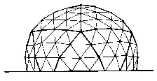
64 Fig. 15 130 5/8 truncation of 4v icosa—as basis of geodesic dome.
65 The geodesic pattern is also a variable. In addition to the above "checkerboard", Fuller developed a number of other "geodesic breakdowns". [240/241]An icosahedral face can be subdivided by a variety of patterns—each one yielding a different design for potential domes. The most common breakdown subdivides each triangular face with lines parallel to its three edges as explained above (Fig. 15-131.a). The number of segments along each icosahedral edge specifies the frequency of the resulting geodesic dome, and the number of triangles per icosa face will always be f ² for an "f -frequency" structure. A geodesic dome might be 2-frequency or 32-frequency depending on size and material; there's no inherent upper limit, but the exponentially increasing numbers of different strut types become prohibitively complicated at very high frequencies.
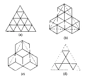
67 Fig. 15 131 Geodesic pattern possibilities
68 The second breakdown subdivides icosahedral faces into triangles with lines perpendicular to icosahedral edges, producing slightly fewer triangles on the overall structure than the parallel version (12 per face for a 4-frequency breakdown, as compared to 16) and is somewhat less symmetrical (Fig. 15-131.b). Fuller's diamond pattern is yet another choice (Fig. 15-131.c). This design is unstable unless constructed out of panels rather than struts. If the situation allows mass production of panels, the diamond pattern will have an advantage over the first breakdown because of its fewer different types of faces. A number of aluminum domes have been built according to this design.
69 Finally, the deliberate omission of certain chords in Fig. 15-131.a produces Fuller's "basket-weave" design, characterized by hexagons [241/242]and pentagons entirely framed by triangles (Fig. 15-131.d). This pattern lends itself to building domes out of bamboo for example: struts in a 3-way weave are simply tied together at crossings.
70 There are many other potential designs. The field is as wide open as the number of ways to symmetrically subdivide an icosahedron with great-circle chords. The fundamental characteristics of the resulting enclosures are the same. Geometric principles are exploited to gain unprecedented structural efficiency, just as nature, in response to the interplay of physical forces and the constraints of space, produces icosahedral geodesic patterns for many enclosures.
71 Geodesic domes of virtually unlimited size can be built by increasing the frequency as needed. The mathematics behind this undertaking is cumbersome but not conceptually difficult. Calculations are simplified (or at least kept under control) by an understanding of symmetry: complete information for an entire dome of any frequency is contained within its LCD triangle. Using the formulae of spherical trigonometry, we can manipulate the central and surface angles of spherical triangles to derive values with which to obtain strut lengths. Struts are great-circle chords, and each one is subtended by a specific central angle (Fig. 15-132.a).
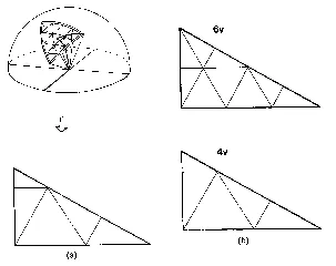
73 Fig. 15 132 LCD in higher frequencies
74 (a) Use of LCD in geodesic-dome calculations.
(b) Examples: LCD for 6v and 4v icosahedral geodesic domes.
75 Depending on construction methods and materials, we might strive to keep struts as close to the same length as possible, or instead try to develop triangles with maximally similar shapes, or work toward any number of other preferred solutions. Frequency is itself an important variable; greater numbers of shorter struts may be more efficient in terms of supporting loads, but construction is correspondingly more difficult. Such tradeoffs must be carefully weighed, and fortunately trigonometry allows enormous flexibility in terms of potential solutions. Taking advantage of symmetry, we are able to experiment with different strut lengths in the LCD triangle, thereby only manipulating angles and lengths for a very small portion of the whole system, while developing the mathematical specifications for an entire geodesic dome (Fig. 15-132.b). Finally, geodesic domes can be elongated or pear-shaped, or (theoretically) even shaped like elephants. The constant curvature of a sphere produces the greatest strength, but these other options do exist and can be developed with no more than a pocket calculator and a lot of paper.
76 As a final note, it is important to realize that while the theory behind geodesic domes is strikingly simple—and previously contemplated by others before Fuller was granted U.S. Patent 2,682,235 in 1954—the actual translation from theory to practical structures involved fantastically intricate mathematical development. As with [242/243]most invention and design, the initial insight was not enough to produce a 250-foot-diameter (76m) clear-spanning structure overnight. The subsequent calculations required enormous aptitude and perseverance. Consider the precision necessary to have six struts meeting at the same point, at thousands of different vertices; minute errors in strut lengths at only a few points will accumulate and produce vast discrepancies elsewhere on the dome. Dealing with tolerances similar to that of the aircraft industry rather than the relatively crude building world, Fuller had to develop absolutely reliable trigonometric data to enable the construction of extremely large domes.
15.0.1 Tensegrity
77Before geodesic domes appeared on the scene in 1948, the dome of St. Peter's Cathedral in Rome, with a diameter of 150 feet (46m), was unchallenged as the largest architectural clear span. 150 feet (46m) must have been seen as a fundamental upper limit, a sort of divine zoning [243/244]law. Ultimately, the inherent stability of triangles cannot alone account for the geodesic dome's ability to span unlimited distances with no interior supports—nor for its unprecedented strength-to-weight ratio.
78 The rest of the explanation lies in an understanding of tensegrity, Fuller's contraction of the two words tension and integrity.
79 "Tensegrity describes a structural-relationship principle in which structural shape is guaranteed by the…continuous, tensional behaviors of the system and not by the discontinuous exclusively local compressional member behaviors" (700.011)
80 Fuller thus introduces a discussion of the interplay of tension and compression forces in Universe. His term also refers to the inescapable co-occurrence of tension and compression, while its first syllable emphasizes the too often overlooked role of tension.
81 All systems consist of some combination of tension and compression forces. The two are inseparable.
82 All systems? What about a simple piece of nylon rope pulled at both ends between two hands? Isn't that pure tension?
83 Try to visualize the experiment: pull as hard as you can on both ends and notice what happens to the thickness of the rope. Its diameter shrinks slightly, betraying the invisible compression force around the rope's circumference, or perpendicular to the applied tension. Even in this simple example, unplanned compression is inevitable.
84 The same is true in reverse. Applying compression to a column introduces surface tension around its girth. Pushing from both sides along the long axis of a strut causes the outside surface to stretch, albeit slightly. Tension and compression go hand in hand, as simultaneous complementary functions; however one or the other usually dominates a given situation.
85 641.01 No tension member is innocent of compression, and no compression member is innocent of tension…
86 641.02 Tension and compression are inseparable and coordinate functions of structural systems, but one may be at its "high tide" aspect, i.e., most prominent phase, while the other is at low tide, or least prominent aspect. The visibly tensioned rope is compressively contracted in almost invisible increments of its girth dimensions…. This low-tide aspect of compression occurs in planes perpendicular to its tensed axis….
87 We thereby draw the distinction: our rope is a tension element; the loaded column, a compression member. Effective design must balance the two interdependent forces in preferred ways.[244/245]
88 Note that the engineering term "pure axial force" is thus a convenient simplification, which is effective in terms of structural analysis, rather than an accurate scientific description. A strut which is to carry either axial compression or tension can be significantly lighter than one which is subject to bending or torque.
89 The apparently insurmountable limit to the clear-span of a structure existed because the interdependence of tension and compression was not fully understood. In general, the history of construction reveals an overwhelming dependence on compression. Our concept of building has been inseparably tied to that of weight; early humanity piled one stone on top of another, and we continue to employ the same single strategy, fighting gravity with sheer mass. But compressional continuity has its limits, such as the impossibility of achieving spans greater than 150 feet (46m). Any larger dome would collapse under the force of its own weight. Moreover, although architects may not have reflected on the principles of tensional integrity, necessity apparently forced them to add a powerful iron chain around the base of St. Peter's dome; the outward thrusts from all that compression needed further restraint.
90 Fuller decided that a better approach was needed than that of slapping on a bandage at the end. Following nature's example, tension must be designed into the structure at the start. In fact, tension must be primary.
Nature's Example
92Look around; nature's been using tensegrity all along. Humanity was able to overlook this structural truth for thousands of years because tension tends to be invisible. Seeing rocks sitting on the ground and bricks piled upon bricks, we have developed a virtually unshakable "solid-things" understanding of how Universe works. The ubiquitous tension forces, from gravity to intermolecular attraction, tend to be more subtle:
93 …at the invisible level of atomic structuring the coherence of the myriad atomic archipelagos of a "single" pebble's compressional mass is provided by comprehensively continuous tension. This fact was invisible to and unthought of by historical man up to yesterday…there was naught to disturb, challenge or dissolve his "solid things" thinking…49
94 The inseparable partnership of tension and compression does not mean that the two forces are the same. On the contrary, fundamental differences are the basis of their successful interdependence.
95 Compression is local, discontinuous, says Bucky. When we load a column, we push it together. If we push a thin column too hard, the column will buckle like a banana; there is no other way for the stressed member to yield. For this reason, compression members are subject to an inherent limit to their length relative to their cross-sectional area, called the "slenderness ratio". The development of stronger materials has increased that ratio only slightly over thousands of years: from a maximum of 18:1 for stone columns in ancient Greece to approximately 33:1 for modern steel. The limit is not as much a result of inadequate materials as of geometry: compression is directed inward, and hence eventually forces the overstressed column to buckle. Compression fights against the shape of a strut.
96 Tension, on the other hand, pulls apart. The direction of tension serves to reinforce the shape of the stressed member. Pulling straightens; pushing bends. As a result, assuming stronger and stronger materials, there is no inherent geometrical limit to the length of a tension component. While the capability of compression members has remained more or less the same, tension materials have improved by leaps and bounds, and significant advances continue today.
97 Compression was the sole basis of man-made structures until the tensile strength of wood was exploited, enabling for the first time the construction of structures light enough to float on water: simple rafts, initially, followed by progressively more sophisticated rowing and sailing vessels. But at 10,000 pounds per square inch, the tensile strength of wood was still overshadowed by the 50,000 psi compression strength of stone masonry. Not until 1851 saw the first mass production of steel—with a tensile strength equal to its compression-resisting capability of 50,000 psi—was tension finally brought into parity with compression, explains Fuller; "so tension is a very new thing". This development enabled the Brooklyn Bridge in 1883 and ushered in a whole new era of tensional design. Scientists rapidly created metal alloys of greater and greater tensile strength with less and less weight, ultimately leading to jet airplanes and other previously inconceivable miracles. A new material called carbon fiber, with an unprecedented 600,000 psi, was responsible for a recent "miracle". In 1979, the first human-powered aircraft—Paul MacCready's Gossamer Albatross—was pedaled over the English Channel; 2 years later the journey was repeated with a completely solar-powered plane. The only reason this feat could be accomplished, emphasizes Fuller, was that the extraordinary tensile strength of carbon fiber allowed the plane to have a wing span of 97 feet (29m), while weighing only 71 pounds (32kg); you could hold it up in one hand. But the newspapers didn't mention the carbon fiber, he declares sternly; "nobody talks about this invisible capability". [246/247]This beautiful example of "doing more with less" was a favorite for Bucky, who never forgot being told by well-meaning adults during his first 8 years, "Darling, it is inherently impossible for man to fly".
98 Driving toward a specific observation about Universe, Bucky describes theoretically ideal structural components for each of the two forces, as suggested by their different characteristics. Why will a short fat column not buckle under a compressive force that easily breaks a tall thin column of the same material and weight? Geometry governs the situation as follows. A system is most resistant to compression in one direction, namely along an axis perpendicular to its widest cross-section, in which case, its vulnerable girth is as strong as possible. This is the neutral axis. The wider its girth, the more impervious a column will be to compression. Therefore, a short fat column is better able to resist buckling than a tall thin column of the same material and weight, because the latter lacks sufficient resistance perpendicular to the line of force. Similarly, if a compression force that will easily break a long column (a pencil, for example) is applied perpendicular to its length, that column will be unharmed (Fig. 15-133.a, Fig. 15-133.b).
99 That much is common sense, but in less extreme situations an understanding of the "neutral axis" is necessary to enable the prediction of exact results.
100 Next, imagine loading a slightly malleable cigar-shaped column; compression causes the girth to expand, forcing the column to become progressively more spherical. This transformation suggests a candidate for the ideal compression component (Fig. 15-133.c).
101 A sphere is the only shape in which every axis is a neutral axis, which is to say, a sphere's width is the same in every orientation. Therefore, this shape resists compression from any direction; it cannot buckle. Hence the ball bearing. This tangible example illustrates the ideal design for compression.
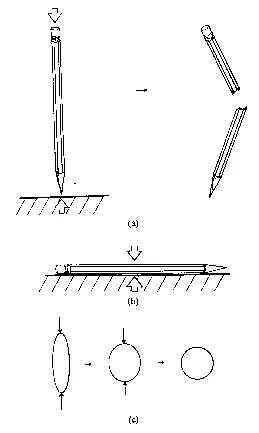
103 Fig. 15 133 Compression: neutral axis, girth, and spherical limit case
104 What about tension? Evidence of longer, thinner, and ever more resilient tension materials suggests that there's no inherent limit to length. Fuller takes this a step further:
105 "May we not get to where we have very great lengths and no cross-section at all?"
106 He answers his own question,
107 "This is just the way Universe is playing the game".
108 Gravity is that invisible limitless tension force.
109 "The Earth and the Moon are invisibly cohered…";
110 The tension cable has reached the limit case in thinness: it's nonexistent.
111 "You have enormous tension with no section at all."
112 A splendid design! The solar system is thus a magnificent tensegrity: discontinuous compression spheres (i.e., planets) [247/248]are intercoordinated—never touching each other—by a sea of continuous tension.
113 "Every use of gravity is a use of…sectionless tensioning", Fuller continues, observing that "this is also true within the atoms: true in the macrocosm and true in the microcosm" (645.03–645.05)
114 By mid-20th-century, it was clear that the design plan of Universe involves islanded compression and continuous tension, but [248/249]up until then
115 …man had been superficially misled into [thinking] that there could be solids or continuous compression. .. Only man's mentality has been wrong in trying to organize the idea of structure. (645.04)
116 New Concept of Construction
117 That humanity can learn from the principles of nature is the essence of Fuller's message. We must abandon our building-block concept of structure in favor of comprehensive solutions which take advantage of the inherent qualities of tension and compression. The latter tends to do the local, isolated structural tasks in nature, while the former specializes in cohering systems over great distances. While we understand that Universe is not structured like a stack of bricks, that awareness has not affected our approach to construction. A "building-block" approach has persisted more or less unchanged for thousands of years, pitting structural bulk against gravity's vigilant force. Instead, argues Fuller, we must think in terms of whole systems in equilibrium, omnidirectional forces interacting in self-stabilizing patterns. If, emulating nature, structural design capitalizes on the integrity of tension, these "whole systems" will prove far stronger than analysis of their separate parts could predict.
118 Additionally, we can learn from nature's structuring method: converging and diverging, she produces bubbles, explosions, stars, and the radially expanding sound and light waves. Energy pushes out, and its expansion is countered by tensional restraints such as the pull of gravity and molecular forces. Eventually, the two dynamics reach an equilibrium, a tentative balance such as a soap bubble.
119 Fuller heralded an
120 "era of thinking and conscious designing in terms of comprehensive tension and discontinuous compression" (640.42).
121 He saw an unmistakable change taking place, largely going unnoticed. This "new era" began with the spoke wheel, which Fuller pinpoints as man's first breakthrough into tensegrity thinking:
122 I saw that his structural conceptioning of the wire wheel documented his intellectual designing breakthrough into such thinking and structuring. The compressional hub of the wire wheel is clearly islanded or isolated from the compressional "atoll" comprising the rim of the wheel. The compressional islands are interpositioned in structural stability only by the tensional spokes…. This reverses the historical structural strategy of man. (640.42)
123 The wheel's use of tension enables a far more efficient and lightweight [249/250]structure than could be produced with compression spokes. Tension materials are inherently smaller and lighter than compression materials carrying equivalent loads.
124 The wheel was originally an exclusively compression structure starting with the cave man's stone cylinder and progressing to slightly more sophisticated designs like "the old artillery wheel" cited by Fuller in Synergetics. fig.640.41 It continues to be perceived as such. (A version of that wheel is sketched in Fig. 15-134.)
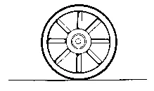
126 Fig. 15 134 Wheel with compression spokes
127 Widespread awareness of the tensional integrity responsible for the spoke wheel's lightweight efficiency has not been reached. The load on a bicycle wheel is therefore often seen as "sitting" on the lower spokes-like columns—rather than hanging from the top spokes. Despite design breakthroughs, humanity as a whole is still caught in "solid-things" thinking.
128 Many other structures that rely on tensional integrity can be cited, such as suspension bridges and sailboats. However, Fuller points out that tension was usually incorporated as a "secondary accessory of primary compressional structuring". In other words, ancient man—habitually relying on compressional continuity—inserted a "solid" mast into his hull, but finding that the wind kept blowing his mast over, he added a set of stabilizing tension wires, or slays, in nautical terminology. Somehow he failed to learn from his accidental design, in which the extraordinarily thin, lightweight tension adjuncts withstand the same forces as the heavy solid mast.
129 Tension has been secondary in all man's building and compression has been primary, for he always thought of compression as solid.… Earth and ship seemed alike, compressionally continuous. (640.50)
Modeling the Invisible
131Tensional integrity is certainly how Universe works, pondered Bucky in the 1940s, but how can I illustrate this invisible phenomenon? Can the co-occurrence of discontinuous compression and continuous tension be modeled in such a way as to bring this structural principle [250/251] into easy grasp? He was determined to display the invisible truths of science in a scale that can be perceived by human senses.
132 Could it be done? Could discontinuous reality be modeled?
133 Science in the 20th century feels exempt from modelability, philosophized Bucky; ever since the isolation of the electron in 1898, scientists have felt increasingly more sure of their lack of responsibility to explain their work to the layman. The hypothetical scientist of Fuller's lectures declares, "I am sorry to say, reality is both invisible and unmodelable".
134 In the summers of 1947 and 1948, Fuller taught at Black Mountain College, and spoke constantly of "tensional integrity". Universe seems to rely on continuous tension to embrace islanded compression elements, he mused; we must find a way to model this structural principle. Much to his delight, a student and later well-known sculptor, Kenneth Snelson, provided the answer. He presented his discovery to Fuller: a small structure consisting of three separated struts held rigidly in place with a few strings. This was the birth of an explosion of geometric tensegrity structures. Inspired by Snelson's discovery, Fuller went on to create tensegrity versions of countless polyhedra.
Tensegrity Polyhedra
136Tensegrities can be derived from all polyhedra, whether regular, semiregular, high-frequency geodesic, or irregular, typically with one strut representing each edge of the polyhedron. Struts do not come in contact with each other, but instead are held in place by a network of tension elements, or strings—producing completely stable sculptural systems. The complexity of molecular interactions aside, the two types of components are characterized by axial-force states, thereby using materials most efficiently, because components can be far lighter than would be required to withstand bending. The technical sound of the words in no way prepares you for the exquisite appearance of these structures. Photo 15-2 shows a tensegrity icosahedron and tetrahedron, while Photo 15-3 displays a 3v tensegrity icosahedron, as representative tensegrity polyhedra. However, there's no substitute for actual models.
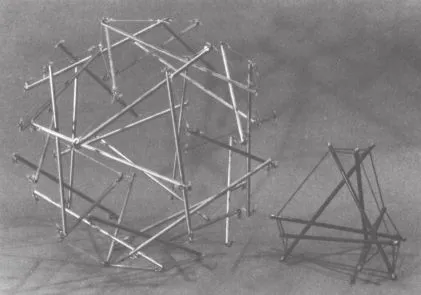
138 Photo 15 2 Tensegrity icosahedron and tensegrity tetrahedron.
139 Photograph by Amy C. Edmondson.
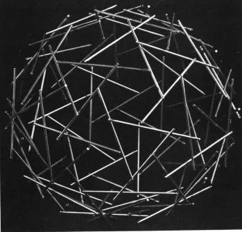
141 Photo 15 3 3v tensegrity icosahedron with 90 struts.
142 Photograph courtesy of Thomas T. K. Zung, Buckminster Fuller, Sadao and Zung Architects. Cleveland, Ohio.
143 At last, says Bucky, we are able to experience at first hand the truth about structure: systems cohere through tensional continuity, and nothing in Universe touches anything else:
144 …Tensegrity structures satisfy our conceptual requirement that we may not have two events passing through the same point at the same time. Vectors [i.e., struts] [251/252]converge in tensegrity, but they never actually get together; they only get into critical proximities and twist by each other. (716.11)
145 A tensegrity icosahedron, therefore, is more honest than a toothpick-marshmallow structure which seems to have five edges touching at each vertex. In the tensegrity, edges all come within critical proximity of the location of a "vertex" and "twist by each other". Fig. 15-135 illustrates the relationship between the tensegrity icosahedron and its Platonic counterpart.
146 Instead of a 5-valent "point" with the illusion of continuity, each convergence is marked by a pentagon of string, thus illustrating the fact that individual energy events do not touch but instead hover in a state of dynamic equilibrium. Tensegrity structures provide a visible, tangible illustration of an invisible truth. Forces and their interactions are brought out in the open.
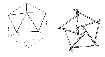
148 Fig. 15 135 Tensegrity icosahedron and its Platonic (planar) counterpart.
149 Perhaps the most significant lesson from tensegrity structures lies in their unexpected strength. A tensegrity's apparent extreme fragility is completely deceptive. The uninformed observer will usually approach such a structure with great caution, touch it hesitantly and gently so as not to break the delicate model, and (if persistent) ultimately realize that a tensegrity can be thrown around the room without harm. The erroneous initial assumption is a result of a deeply ingrained bias in favor of compression as the reliable source of structure. We perceive string and cable as flimsy, but actually the [252/253]magnitude of a force that can be carried by "delicate" tension materials can far exceed the corresponding capacity of compression elements. Humanity's perception is in need of retuning.
150 The other aspect of a tensegrity's remarkable strength is the rapid omnidirectional distribution of applied forces. One of the advantages of a network of tension elements is efficient dispersal of loads around a structure, enabling the whole system to withstand forces far greater than could be predicted by engineering analysis of the separate components. Welcome back, synergy:
151 This is not the behavior we are used to in any structures of previous experiences… Ordinary beams deflect locally… The tensegrity "beam" does not act independently but acts only in concert with "the whole building", which contracts only symmetrically when the beam is loaded…. The tensegrity system is synergetic.…(724.33–724.34)
152 This "whole system" behavior can be detected by pushing or pulling [253/254]on two opposite struts of certain tensegrities. The entire system will contract or expand symmetrically like a balloon, and also will spring back to its equilibrium configuration when the applied force is removed. (Photo 15-4 shows the simple 6-strut tensegrity, which is arguably the most elegant illustration of this uniform contraction or expansion in response to a unidirectional force.) Similarly, this synergetic behavior insures a balanced distribution of stresses:
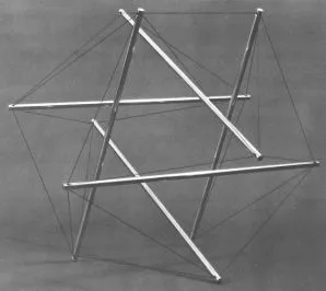
154 Photo 15 4 Six-strut "expanded octahedron" tensegrity.
155 Photograph courtesy of the Buckminster Fuller Institute, Los Angeles, CA
156 If you…tauten one point in a tensegrity system, all the other parts of it tighten evenly. If you twang any tension member anywhere in the structure, it will give the same resonant note as the others. (720.10)
157 Fuller felt that this dispersal is not really understood by most engineers, and as a result, they have been unable to predict or analyze the extraordinary capabilities of tensegrities and geodesic domes. Note that discontinuous compression and continuous tension also characterize geodesic domes, but as these structures lack the visually legible quality of the geometric models, one cannot at a glance identify the operative forces:
158 Structural analysis and engineering—design strategies…were predicated upon the stress analysis of individual beams, columns, and cantilevers as separate components…[and] could in no way predict, let alone rely upon, the synergetic behaviors of geodesics…. Engineering was, therefore, and as yet is, utterly unable to analyze effectively and correctly tensegrity geodesic structural spheres in which none of the compression members ever touch one another and only the tension is continuous. (640.02)
159 The ultimate result of this conceptualizing and model building is that the barrier to ever-larger clear-spanning enclosures has been [254/255]removed. By understanding the crucial role of tension, we can learn to manipulate it in preferred ways.
160 "We are able to reach unlimited spans because our only limitation is tension, where there is no inherent limit to cross-section due to length" (764.02).
161 Cosmic zoning laws are repealed.
Pneumatics
163We recall Fuller's great-circle description in which a vast number of gas molecules are bouncing around inside a sphere, with their great-circle chords ultimately describing an icosahedral pattern as a result of spatial constraints. Tensegrity now completes the image.
164 Fuller explains that tensegrity provides a tangible demonstration of what happens inside a balloon. We tend to think of the balloon's skin as a continuous surface; however, a more accurate picture is [255/256]that of a network of molecules in close proximity, such that the spaces between them are smaller than air molecules, allowing the network to act as an effective cage:
165 The balloon is indeed not only full of holes, but it is in fact utterly discontinuous. It is a net and not a bag. In fact, it is a spherical galaxy of critically neighboring energy events. (761.03)
166 Gas molecules push out against the tensed rubber net and a dynamic equilibrium is maintained; compression and tension are in balance.
167 Our eyes cannot see the bustling molecular activity of the balloon, and Fuller sees synergetics as a way to help us tune in to this invisible behavior. A high-frequency tensegrity icosahedron does just that:
168 In the geodesic tensegrity sphere, each of the entirely independent, compressional chord struts represents two oppositely directioned and force-paired molecules. The tensegrity compressional chords do not touch one another. They operate independently, trying to escape outwardly from the sphere, but are held in by the spherical-tensional integrity's closed network system of great-circle connectors…(703.16)
169 He elaborates on the parallel, holding up his icosahedral tensegrity that has traveled with him to hundreds of lectures:
170 "This is a balloon, except that the tension components are only placed right where they're needed".
171 It's a balloon with all the excess tension taken out; strings are located only where the strut (molecule) wants to impinge on the sphere's surface.
172 We are thus led back to the necessity of 3-way great-circling:
173 A gas-filled balloon is not stratified. If it were, it would collapse like a Japanese lantern…. Once we have three or more…push–pull paths [of paired kinetic molecules] they must inherently triangulate by push–pull into stabilization of opposite angles. Triangulation means self-stabilizing; which creates omnidirectional symmetry; which makes an inherent 3-way spherical symmetry grid; which is the geodesic structure. (766.02–766.04)
174 The analogy is complete. Pneumatics are dynamic high-frequency tensegrity geodesic configurations.
175 The principle of tensegrity, perhaps more than any other single aspect of synergetics, has yet to be exploited to its real potential in terms of design advantage. But the elegant simplicity of these remarkable structures hints at the nature of a future design revolution—toward innovative designs with unprecedented performance per pound. Finally, the tensegrity system, besides suggesting structural applications, has also provided a useful model in science.[256/257]
Case in Point: Donald Ingber
177One striking example was contributed to the growing list in 1983 by Donald Ingber, then a doctoral student at Yale University working on the biology of tumor formation and malignant invasion. Ingber had been exposed to tensegrity structures in an undergraduate design course—a playful option on the other end of the academic spectrum, which was to influence his vision as a scientist in profound ways.
178 While pursuing his research in cell biology, Ingber began to observe some fundamental similarities between the subjects of his two seemingly opposite investigations. It appeared that tensegrity theory was applicable to biological systems; that is, Fuller's structures exhibited certain dynamic characteristics that were analogous to cell and tissue behavior. Significant structural parallels between the behavior of cellular and tensegrity systems led Ingber to powerful insights about the regulation of cell shape, differentiation, and growth, and thereby suggested a strategy for further investigation.
179 This very general summary is based on Dr. Donald Ingber's paper, "Cells as Tensegrity Structures: Architectural Regulation of Histodifferentiation by Physical Forces Transduced over Basement Membrane", published as a chapter in Gene Expression During Normal and Malignant Differentiation, (L. C. Anderson, C. G. Gahrnberg, and P. Ekblom, eds.; Orlando, Fla.: Academic Press, 1985), pp.13–22.
180 Ingber proceeded to build, test, and study tensegrity structures in an effort to understand the implications of his proposed model, and was excited by the results of the comparison. His revolutionary approach has led to significant breakthroughs in his research into cancer formation, which he now continues at Harvard University Medical School. Without a detailed description of Ingber's research, we can still profit by the theme of his radical theory.
181 In a 1983 letter to Fuller, Ingber proposes a "whole system" approach in which
182 "the architectural form of a tissue may itself serve to coordinate and regulate the shape, orientation, and growth of its individual cells through transmission of the physical forces of tension and compression characteristic of a given three dimensional configuration."
183 There is no more appropriate conclusion than Ingber's own description in the letter:
184 The beauty of life is once again that of geometry with spatial constraints as the only unifying principle. It is of interest to note that, as presented in the accompanying paper, cancer may then be viewed as the opposite of life resulting from a breakdown of this geometric hierarchy of synergetic arrangements.50[257/258]